Page 2044 of 2389

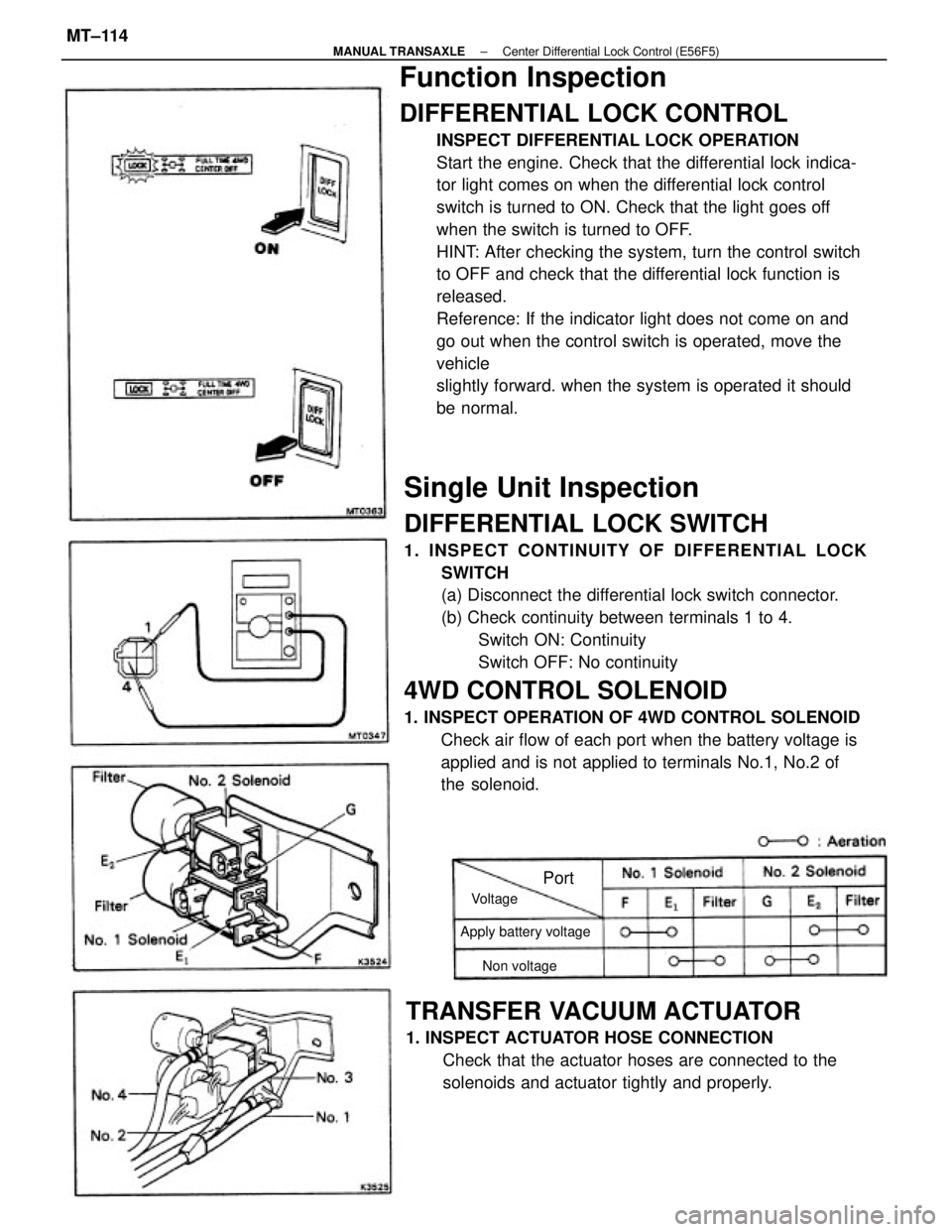
Single Unit Inspection
DIFFERENTIAL LOCK SWITCH
1. INSPECT CONTINUITY OF DIFFERENTIAL LOCK
SWITCH
(a) Disconnect the differential lock switch connector.
(b) Check continuity between terminals 1 to 4.
Switch ON: Continuity
Switch OFF: No continuity
4WD CONTROL SOLENOID
1. INSPECT OPERATION OF 4WD CONTROL SOLENOID
Check air flow of each port when the battery voltage is
applied and is not applied to terminals No.1, No.2 of
the solenoid.
Function Inspection
DIFFERENTIAL LOCK CONTROL
INSPECT DIFFERENTIAL LOCK OPERATION
Start the engine. Check that the differential lock indica-
tor light comes on when the differential lock control
switch is turned to ON. Check that the light goes off
when the switch is turned to OFF.
HINT: After checking the system, turn the control switch
to OFF and check that the differential lock function is
released.
Reference: If the indicator light does not come on and
go out when the control switch is operated, move the
vehicle
slightly forward. when the system is operated it should
be normal.
TRANSFER VACUUM ACTUATOR
1. INSPECT ACTUATOR HOSE CONNECTION
Check that the actuator hoses are connected to the
solenoids and actuator tightly and properly.
Apply battery voltage
Non voltage Voltage
Port
± MANUAL TRANSAXLECenter Differential Lock Control (E56F5)MT±114
Page 2223 of 2389
HINT
wPerform all voltage and resistance measurements with the ECU connected.
wVerify that the battery voltage is 11 V or above with the ignition switch is ON.
Stop light SW ON (Brake pedal depressed) or defogger
SW ONNo trouble (ºCHECKº engine warning light off) and
engine running
Check connector TE 1 ± E 1 not connected
Specifications (Cont'd)
Check connector TE1 ± E1 connected
*1 W/O ECT *2 W/ EGT *3
A/C
EGR gas temp.
sensor
(CALIF.. only)
Ex. shift position P or N rangeIntake air temp. 205C (685F) Measuring plate fully closed
Coolant temp. 805C (1765F)
Shift position P or N rangeMeasuring plate fully open Throttle valve fully closed
Throttle valve fully closed
Heater blower SW ON Air conditioning ONThrottle valve open
Throttle valve open
Throttle valve open
Cranking or idlingSTD voltage (V)
3,000 rpmEG SW ON
IG SW ON IG SW ONIG SW ONIG SW ON
IG SW ON
Cranking
Terminals
Condition
Voltage
Idling
ECU
± SERVICE SPECIFICATIONSEFI System (3S±FE)A±12
Page 2227 of 2389
HINT:
wPerform all voltage and resistance measurements with the ECU connected.
wVerify that the battery voltage is 11 V or above with the ignition switch is ON.
No trouble (ºCHECKº' engine warning light off) and
engine running
Specifications (Cont'd)
Stop light SW ON (Brake pedal depressed)Check connector TE1 ± E1 not connected
Check connector TE1 ± Et connected
Shift position P or N range
Ex shift position P or N rangeIntake air temp. 205C (685F) Measuring plate fully closed
Coolant temp. 605C (1765F) Measuring plate fully open Throttle valve fully closed
Heater blower SW ON Air conditioning ONThrottle valve open
Throttle valve open
Cranking or idling Heater resistance
STD voltage (V) Oxygen
sensor
IG SW ON
IG SW ONIG SW ON
IG SW ONIG SW ON
IG SW ONCranking Terminals
Condition Voltage
Idling
*1 w/ rpm ECU
± SERVICE SPECIFICATIONSEFI System (2VZ±FE)A±15
Page 2232 of 2389
Air gap
Signal generator (pickup coil) resistance
STARTING SYSTEM
Rated voltage and output power
No±toad characteristic
Rated output
Rotor coil resistance
Slip ring diameter
IGNITION SYSTEM
Circle runout
Spring installed loadCommutator
Outer diameter
CHARGING SYSTEM
Secondary coil resistance
Alternator regu-
lator (ICSBattery specific gravityPrimary coil resistance
Brush exposed length High±tension
cord
Regulating voltage Drive belt tensionUndercut depth Ignition timing
See page A±2 Bruch length Ignition coilFiring order
Spark plug
Resistance
Distributor
AlternatorStarter
± SERVICE SPECIFICATIONSIgnition SystemA±19
Page 2233 of 2389
Air gap
Signal generator (pickup coil) resistance
STARTING SYSTEM
Rated voltage and output power
No±toad characteristic
Rated output
Rotor coil resistance
Slip ring diameter
IGNITION SYSTEM
Circle runout
Spring installed loadCommutator
Outer diameter
CHARGING SYSTEM
Secondary coil resistance
Alternator regu-
lator (ICSBattery specific gravityPrimary coil resistance
Brush exposed length High±tension
cord
Regulating voltage Drive belt tensionUndercut depth Ignition timing
See page A±2 Bruch length Ignition coilFiring order
Spark plug
Resistance
Distributor
AlternatorStarter
± SERVICE SPECIFICATIONSStarting SystemA±19
Page 2234 of 2389
Air gap
Signal generator (pickup coil) resistance
STARTING SYSTEM
Rated voltage and output power
No±toad characteristic
Rated output
Rotor coil resistance
Slip ring diameter
IGNITION SYSTEM
Circle runout
Spring installed loadCommutator
Outer diameter
CHARGING SYSTEM
Secondary coil resistance
Alternator regu-
lator (ICSBattery specific gravityPrimary coil resistance
Brush exposed length High±tension
cord
Regulating voltage Drive belt tensionUndercut depth Ignition timing
See page A±2 Bruch length Ignition coilFiring order
Spark plug
Resistance
Distributor
AlternatorStarter
± SERVICE SPECIFICATIONSCharging SystemA±19
Page 2310 of 2389

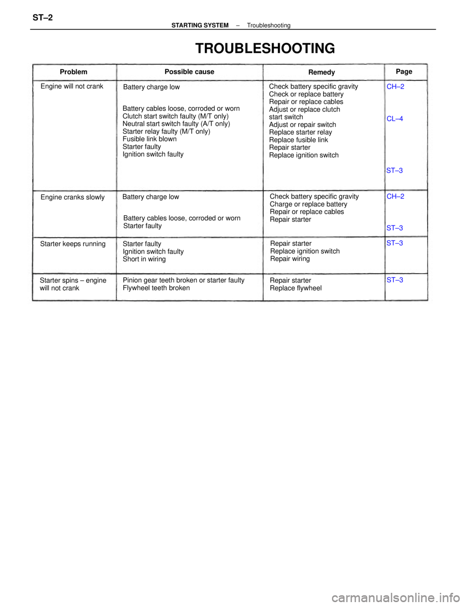
Check battery specific gravity
Check or replace battery
Repair or replace cables
Adjust or replace clutch
start switch
Adjust or repair switch
Replace starter relay
Replace fusible link
Repair starter
Replace ignition switch Battery cables loose, corroded or worn
Clutch start switch faulty (M/T only)
Neutral start switch faulty (A/T only)
Starter relay faulty (M/T only)
Fusible link blown
Starter faulty
Ignition switch faulty
Check battery specific gravity
Charge or replace battery
Repair or replace cables
Repair starter
Pinion gear teeth broken or starter faulty
Flywheel teeth brokenBattery cables loose, corroded or worn
Starter faulty
Repair starter
Replace ignition switch
Repair wiring Starter faulty
Ignition switch faulty
Short in wiring
TROUBLESHOOTING
Starter spins ± engine
will not crankRepair starter
Replace flywheel Engine will not crank
Starter keeps runningBattery charge low
Engine cranks slowlyBattery charge lowPossible cause
Remedy ProblemPage
CH±2
CH±2
ST±3 ST±3
ST±3
ST±3 CL±4
± STARTING SYSTEMTroubleshootingST±2
Page 2312 of 2389

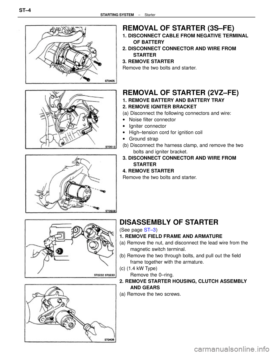
REMOVAL OF STARTER (2VZ±FE)
1. REMOVE BATTERY AND BATTERY TRAY
2. REMOVE IGNITER BRACKET
(a) Disconnect the following connectors and wire:
wNoise filter connector
wIgniter connector
wHigh±tension cord for ignition coil
wGround strap
(b) Disconnect the harness clamp, and remove the two
bolts and igniter bracket.
3. DISCONNECT CONNECTOR AND WIRE FROM
STARTER
4. REMOVE STARTER
Remove the two bolts and starter.
DISASSEMBLY OF STARTER
(See page ST±3)
1. REMOVE FIELD FRAME AND ARMATURE
(a) Remove the nut, and disconnect the lead wire from the
magnetic switch terminal.
(b) Remove the two through bolts, and pull out the field
frame together with the armature.
(c) (1.4 kW Type)
Remove the 0±ring.
2. REMOVE STARTER HOUSING, CLUTCH ASSEMBLY
AND GEARS
(a) Remove the two screws.
REMOVAL OF STARTER (3S±FE)
1. DISCONNECT CABLE FROM NEGATIVE TERMINAL
OF BATTERY
2. DISCONNECT CONNECTOR AND WIRE FROM
STARTER
3. REMOVE STARTER
Remove the two bolts and starter.
± STARTING SYSTEMStarterST±4