1986 TOYOTA CAMRY V20 washer fluid
[x] Cancel search: washer fluidPage 938 of 2389

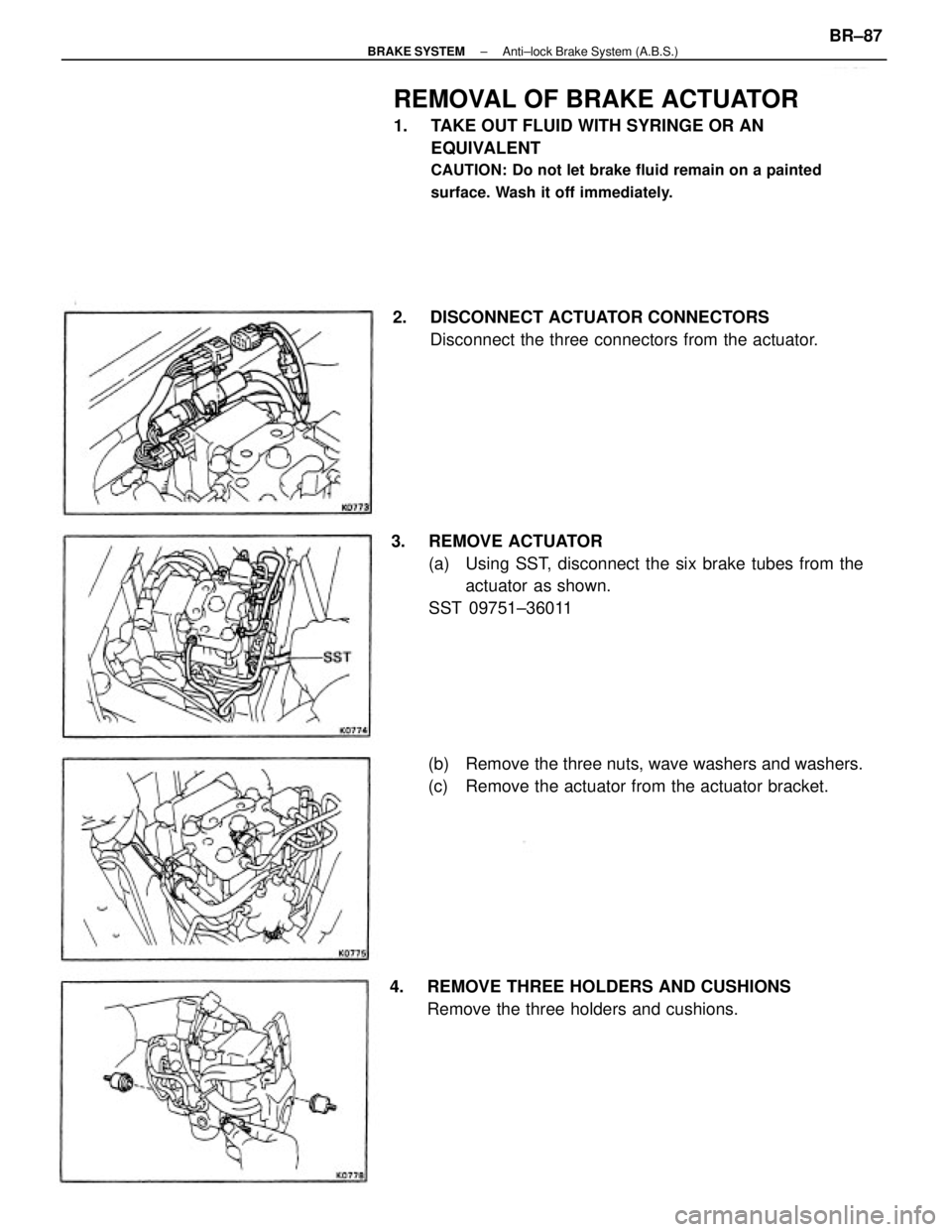
REMOVAL OF BRAKE ACTUATOR
1. TAKE OUT FLUID WITH SYRINGE OR AN
EQUIVALENT
CAUTION: Do not let brake fluid remain on a painted
surface. Wash it off immediately.
3. REMOVE ACTUATOR
(a) Using SST, disconnect the six brake tubes from the
actuator as shown.
SST 09751±36011
(b) Remove the three nuts, wave washers and washers.
(c) Remove the actuator from the actuator bracket. 2. DISCONNECT ACTUATOR CONNECTORS
Disconnect the three connectors from the actuator.
4. REMOVE THREE HOLDERS AND CUSHIONS
Remove the three holders and cushions.
± BRAKE SYSTEMAnti±lock Brake System (A.B.S.)BR±87
Page 943 of 2389

6. INSTALL ACTUATOR
(a) Install the actuator to the actuator bracket in place.
(b) Install the washers, wave washers and nuts.
(e) Tighten the three nuts.
Torque: 55 kg±cm (48 in.±Ib, 5.4 N¿rn)
HINT: Before installing the front right side nut, install the motor
ground terminal between the plate washer and spring washer.
8. FILL BRAKE RESERVOIR WITH BRAKE FLUID AND
BLEED BRAKE SYSTEM
9. CHECK FOR FLUID LEAKAGE
10. CHECK ACTUATOR OPERATION
(See page BR±84) (d) Using SST, connect the six brake tubes to the actua-
tor.
SST 09751±36011
Torque: 155 kg±cm (11 ft±Ib, 15 N±m)
7. CONNECT ACTUATOR CONNECTORS
(a) Connect the three connectors to the actuator.
(b) Bend the wire harness clamp as shown.
± BRAKE SYSTEMAnti±lock Brake System (A.B.S.)BR±92
Page 979 of 2389

REMOVAL OF MASTER CYLINDER
1. DRAW OUT FLUID WITH SYRINGE
2. DISCONNECT CLUTCH LINE TUBE
3. REMOVE INSTRUMENT LOWER FINISH PANEL
Remove the lower instrument lower finish panel and disconnect
the air duct from the instrument lower finish panel.
4. REMOVE CLEVIS PIN AND CLIP WITH SPRING
WASHER
Remove the clip and clevis pin with the spring washer.
5. REMOVE MOUNTING NUTS AND PULL OUT MASTER
CYLINDER
DISASSEMBLY OF MASTER CYLINDER
1. REMOVE RESERVOIR TANK
2. REMOVE PUSH ROD AND PISTON
(a) Pull back the boot and, using snap ring pliers, remove the snap
ring.
(b) Pull out the push rod.
CLUTCH MASTER CYLINDER
COMPONENTS
± CLUTCHClutch Master CylinderCL±5
Page 1914 of 2389

GENERAL MAINTENANCE
These are the maintenance and inspection items
which are considered to be the owner's responsibility,
They can be performed by the owner or he
can have then done at a service shop. These items
include those which should be checked on a daily ba-
sis, those which, in most cases, do not require
(special) tools and those which are considered to be
reasonable for the owner to perform.
Items and procedures for general maintenance are as
follows:
OUTSIDE VEHICLE
1. TIRES
(a) Check the pressure with a gauge. Adjust
if necessary.
(b) Check for cuts, damage or excessive wear.
2. WHEEL NUTS
When checking the tires, check the nuts for looseness
or for missing nuts. If necessary,
tighten them.
3. TIRE ROTATION
It is recommended that tires be rotated every
7,500 miles (12,000 km).
4. WINDSHIELD WIPER BLADES
Check for wear or cracks whenever they do not wipe
clean. Replace if necessary.
5. FLUID LEAKS
(a) Check underneath for leaking fuel, oil, water or
other fluid.
(b) If you smell gasoline fumes or notice any leak,
have the cause found and corrected.
6. DOORS AND ENGINE HOOD
(a) Check that all doors including the trunk lid and
back door operate smoothly, and that all
latches lock securely.
(b) Check that the engine hood secondary latch se-
cures the hood from opening when the prima-
ry latch is released.
INSIDE VEHICLE
7. LIGHTS
(a) Check that the headlights, stop lights, taillights,
turn signal lights, and other
lights are all working.
(b) Check the headlight aiming.8. WARNING LIGHTS AND BUZZERS
Check that all warning lights and buzzers func-
tion properly.
9. HORN
Check that it is working.
10. WINDSHIELD GLASS
Check for scratches, pits or abrasions.
11. WINDSHIELD WIPER AND WASHER
(a) Check operation of the wipers and washer.
(b) Check that the wipers do not streak.
12. WINDSHIELD DEFROSTER
Check that air comes out from the defroster out-
let when operating the heater or air conditioner
at defroster mode.
13. REAR VIEW MIRROR
Check that it is mounted securely.
14. SUN VISORS
Check that they move freely and are mounted
securely.
15. STEERING WHEEL
Check that it has the specified freeplay. Be alert
for changes in steering condition, such as hard
steering, excessive freeplay or strange noise.
16. SEATS
(a) Check that all front seat controls such as
seat adjusters, seatback recliner, etc.
operate smoothly.
(b) Check that a11 latches lock securely in
any position.
(c) Check that the locks hold securely in any
latched position.
(d) Check that the head restraints move up
and down smoothly and that the locks
hold securely in any latched position.
(e) For folding±down rear seat backs, check
that the latches lock securely.
17. SEAT BELTS
(a) Check that the seat belt system such as
buckles, retractors and anchors operate
properly and smoothly.
(b) Check that the belt webbing is not cut,
frayed, worn or damaged.
± MAINTENANCEGeneral MaintenanceMA±16
Page 1915 of 2389

18. ACCELERATOR PEDAL
Check the pedal for smooth operation and uneven
pedal effort or catching.
19. CLUTCH PEDAL (See page CL±3)
Check the pedal for smooth operation.
Check that the pedal has the proper freeplay.
20. BRAKE PEDAL (See page BR±6)
(a) Check the pedal for smooth operation.
(b) Check that the pedal has the proper reserve
distance and freeplay.
(c) Check the brake booster function.
21. BRAKES
At a safe place, check that the brakes do not pull
to one side when applied.
22. PARKING BRAKE (See page BR±8)
(a) Check that the lever has the proper travel.
(b) On a safe incline, check that the vehicle is
held securely with only the parking brake
applied.
23. AUTOMATIC TRANSMISSION PARK
MECHANISM
(a) Check the lock release button of the selector
lever for proper and smooth operation.
(b) On a safe incline, check that vehicle is held
securely with the selector lever in the ºPº
position and all brakes released.
UNDER HOOD
24. WINDSHIELD WASHER FLUID
Check that there is sufficient fluid in the tank.
25. ENGINE COOLANT LEVEL
Check that the coolant level is between the
ºFULLº and ºLOWº lines on the see±through reser-
voir.
26. RADIATOR AND HOSES
(a) Check that the front of the radiator is clean
and not blocked with leaves, dirt or bugs.
(b) Check the hoses for cracks, kinks, rot or
loose connections.
27. BATTERY ELECTROLYTE LEVEL
Check that the electrolyte level of all battery cells
is between the upper and lower level lines on the
case. If level is low, add distilled water only.28. BRAKE AND CLUTCH FLUID LEVELS
(a) Check that the brake fluid level is near the
upper level line on the see±through reser-
voir.
(b) Check that the clutch fluid level is within
+ 5 mm (0.20 in.) of the reservoir hem.
29. ENGINE DRIVE BELTS
Check all drive belts for fraying, cracks, wear or
oiliness.
30. ENGINE OIL LEVEL
Check the level on the dipstick with the engine
turned off.
31. POWER STEERING FLUID LEVEL
Check the level.
The level should be in the ºHOTº or ºCOLDº
range depending on the fluid temperature.
32. AUTOMATIC TRANSMISSION FLUID
LEVEL
(a) Park the vehicle on a level surface.
(b) With the engine idling and the parking
brake applied, shift the selector into all
positions from ºPº to ºLº, and then shift
into ºPº.
(c) Pull out the dipstick and wipe off the fluid
with a clean rag. Re±insert the dipstick
and check that the fluid level is in the HOT
range.
(d) Perform this check with the fluid at normal
driving temperature (70 ± 80
°C or
158 ± 176°F).
NOTE: Wait about 30 minutes before check-
ing the fluid level after extended driving at high
speeds i n hot weather, driving i n heavy traffic
or with a trailer.
33. EXHAUST SYSTEM
Visually inspect for cracks, holes or loose sup-
ports.
If any change in the sound of the exhaust oK
smell of the exhaust fumes is noticed, have the
cause located and corrected.
± MAINTENANCEGeneral MaintenanceMA±17
Page 1932 of 2389

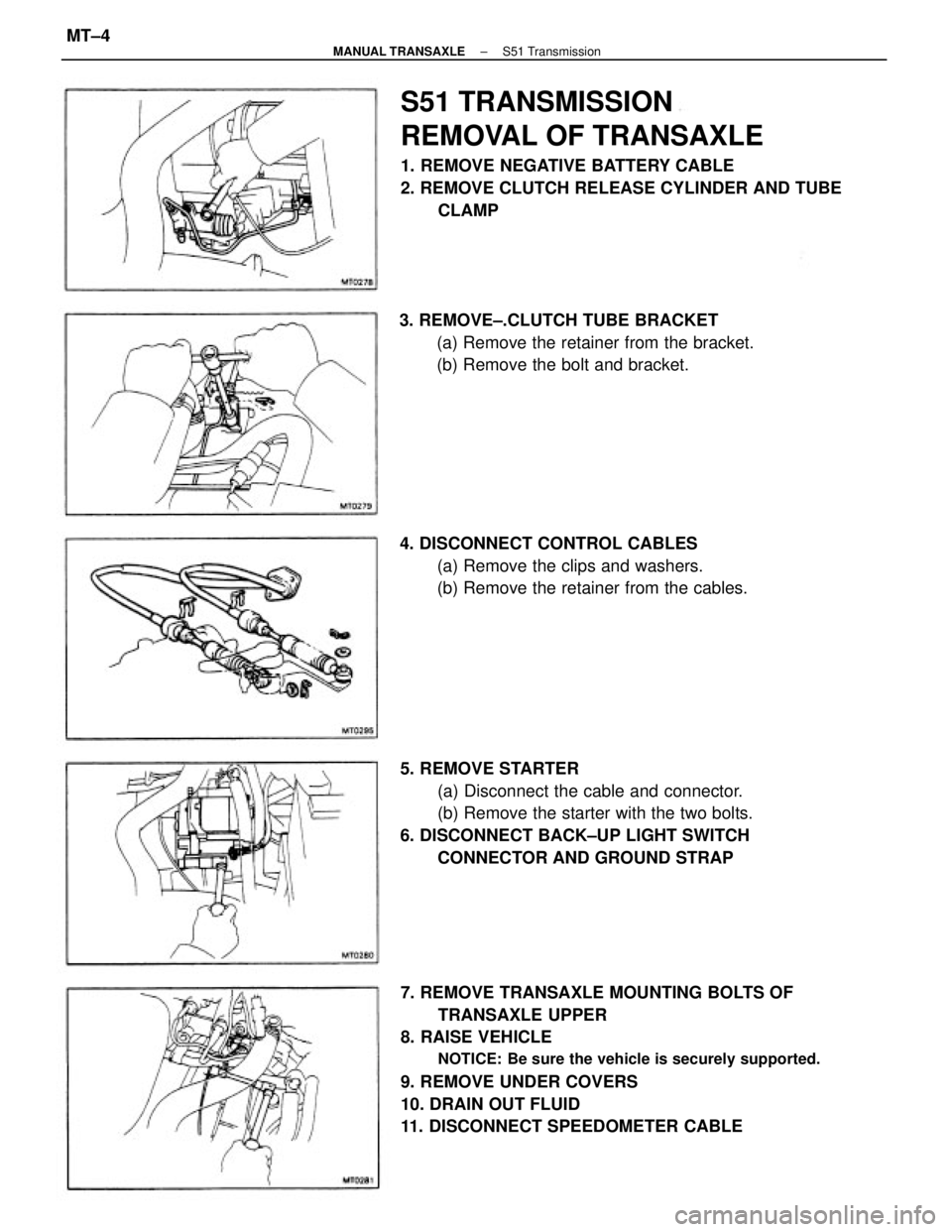
7. REMOVE TRANSAXLE MOUNTING BOLTS OF
TRANSAXLE UPPER
8. RAISE VEHICLE
NOTICE: Be sure the vehicle is securely supported.
9. REMOVE UNDER COVERS
10. DRAIN OUT FLUID
11. DISCONNECT SPEEDOMETER CABLE
S51 TRANSMISSION
REMOVAL OF TRANSAXLE
1. REMOVE NEGATIVE BATTERY CABLE
2. REMOVE CLUTCH RELEASE CYLINDER AND TUBE
CLAMP
5. REMOVE STARTER
(a) Disconnect the cable and connector.
(b) Remove the starter with the two bolts.
6. DISCONNECT BACK±UP LIGHT SWITCH
CONNECTOR AND GROUND STRAP 3. REMOVE±.CLUTCH TUBE BRACKET
(a) Remove the retainer from the bracket.
(b) Remove the bolt and bracket.
4. DISCONNECT CONTROL CABLES
(a) Remove the clips and washers.
(b) Remove the retainer from the cables.
± MANUAL TRANSAXLES51 TransmissionMT±4