Page 1433 of 2389
TERMINAL AND CONNECTOR REPAIR±TERMINAL REPLACEMENT
B±4
14
Wire Harness Repair Manual (RM1022E)
Step 1. Identify the connector and the terminal type.
Confirm whether the connector you require is the non±waterproof, waterproof or combined terminal type
connector from the pictures provided in the following charts.
Connector
Description
Non±Waterproof TypeThose connectors which are not of the
waterproof or combined terminal type.
Waterproof TypeWaterproof material (hole plug or terminal
packing) is provided on the terminal/connector
body.
Combined Terminal TypeTerminals of different shape/size are located in
one connector.
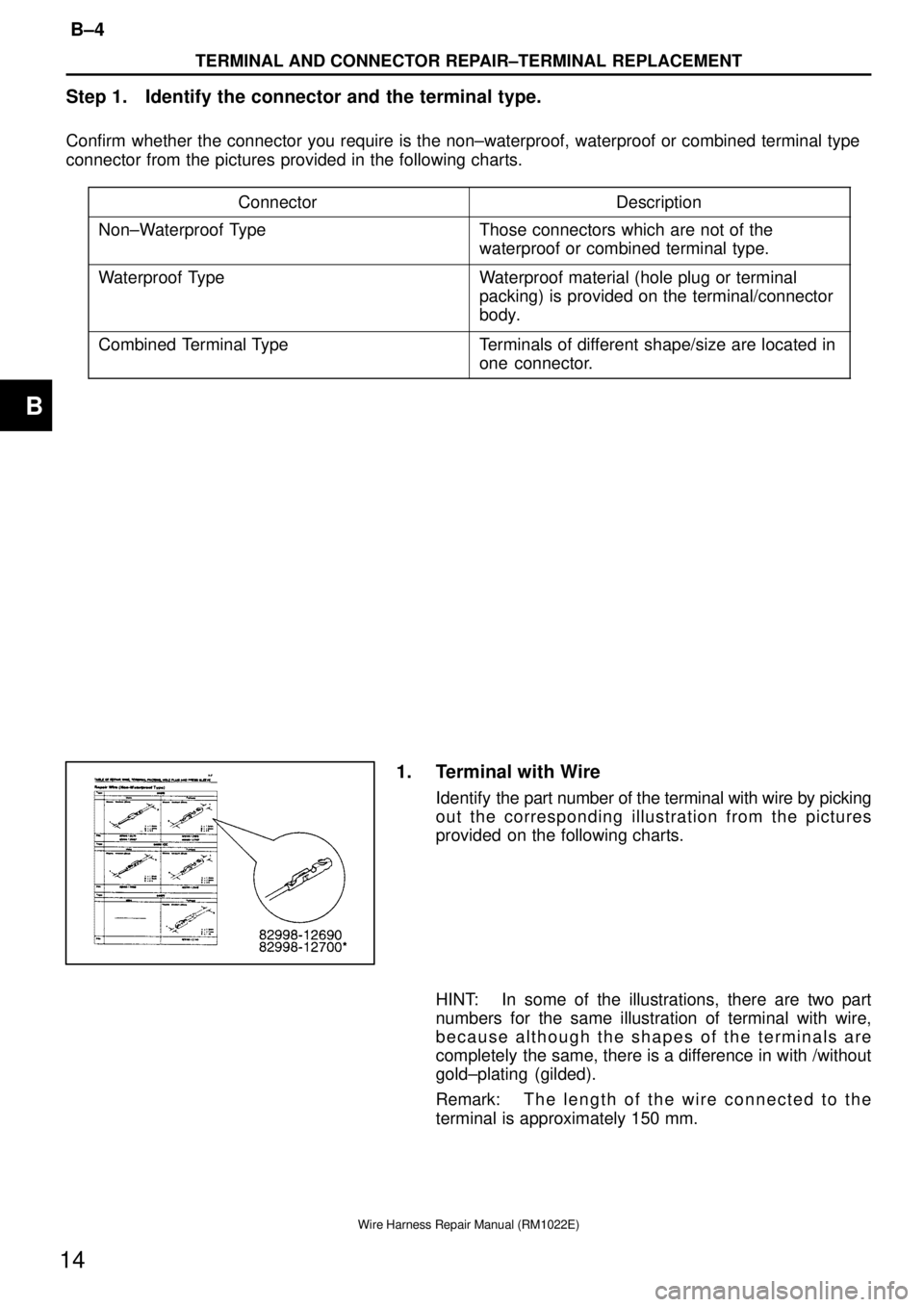
1. Terminal with Wire
Identify the part number of the terminal with wire by picking
out the corresponding illustration from the pictures
provided on the following charts.
HINT: In some of the illustrations, there are two part
numbers for the same illustration of terminal with wire,
because although the shapes of the terminals are
completely the same, there is a difference in with /without
gold±plating (gilded).
Remark: T h e length of the wire connected to the
terminal is approximately 150 mm.
B
Page 1456 of 2389
Step 3. Replace the terminal.
Cut Existing
terminal
New Terminal with lead
82998±12200
Stripped insulation length (A)
approximately 8 to 11 mm
Existing
HarnessSupplied lead
with New Terminal AA
B±27
TERMINAL AND CONNECTOR REPAIR±TERMINAL REPLACEMENT
37
Wire Harness Repair Manual (RM1022E)
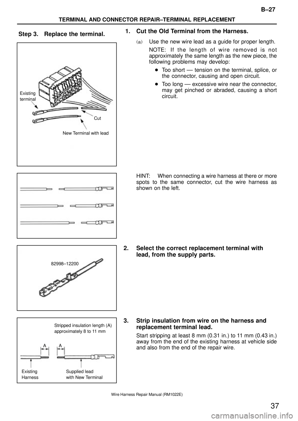
1. Cut the Old Terminal from the Harness.
(a)Use the new wire lead as a guide for proper length.
NOTE: If the length of wire removed is not
approximately the same length as the new piece, the
following problems may develop:
�Too short ±± tension on the terminal, splice, or
the connector, causing and open circuit.
�Too long ±± excessive wire near the connector,
may get pinched or abraded, causing a short
circuit.
HINT: When connecting a wire harness at there or more
spots to the same connector, cut the wire harness as
shown on the left.
2. Select the correct replacement terminal with
lead, from the supply parts.
3. Strip insulation from wire on the harness and
replacement terminal lead.
Start stripping at least 8 mm (0.31 in.) to 11 mm (0.43 in.)
away from the end of the existing harness at vehicle side
and also from the end of the repair wire.
Page 1892 of 2389
REPLACEMENT OF ENGINE OIL
AND OIL FILTER
NOTICE:
wProlonged and repeated contact with mineral oil will re-
sult in the removal of natural¿¿ts from the skin, leading
to dryness, irritation and dermatitis. In addition, used en-
gine oil contains potentially harmful contaminants
which may cause skin cancer.
wCare should be taken, therefore, when changing engine
oil, to minimize the frequency and length of time your
skin is exposed to used engine oil. Protective clothing
and gloves, that cannot be penetrated by oil, should be
worn. The skin should be thoroughly washed with soap
and water, or use waterless hand cleaner, to remove any
used engine oil. Do not use gasoline, thinners, or sol-
vents.
wIn order to preserve the environment, used oil must be
disposed of only at designated disposal sites.
1. DRAIN ENGINE OIL
(a) Remove the oil filler cap.
(b) Remove the oil drain plug, and drain the oil into a container.
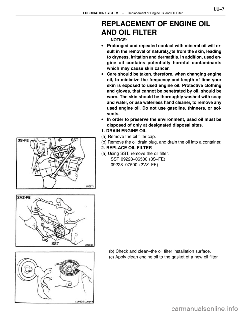
2. REPLACE OIL FILTER
(a) Using SST, remove the oil filter.
SST 09228±06500 (3S±FE)
09228±07500 (2VZ±FE)
(b) Check and clean±the oil filter installation surface.
(c) Apply clean engine oil to the gasket of a new oil filter.
± LUBRICATION SYSTEMReplacement of Engine Oil and Oil FilterLU±7
Page 1919 of 2389
BRAKES
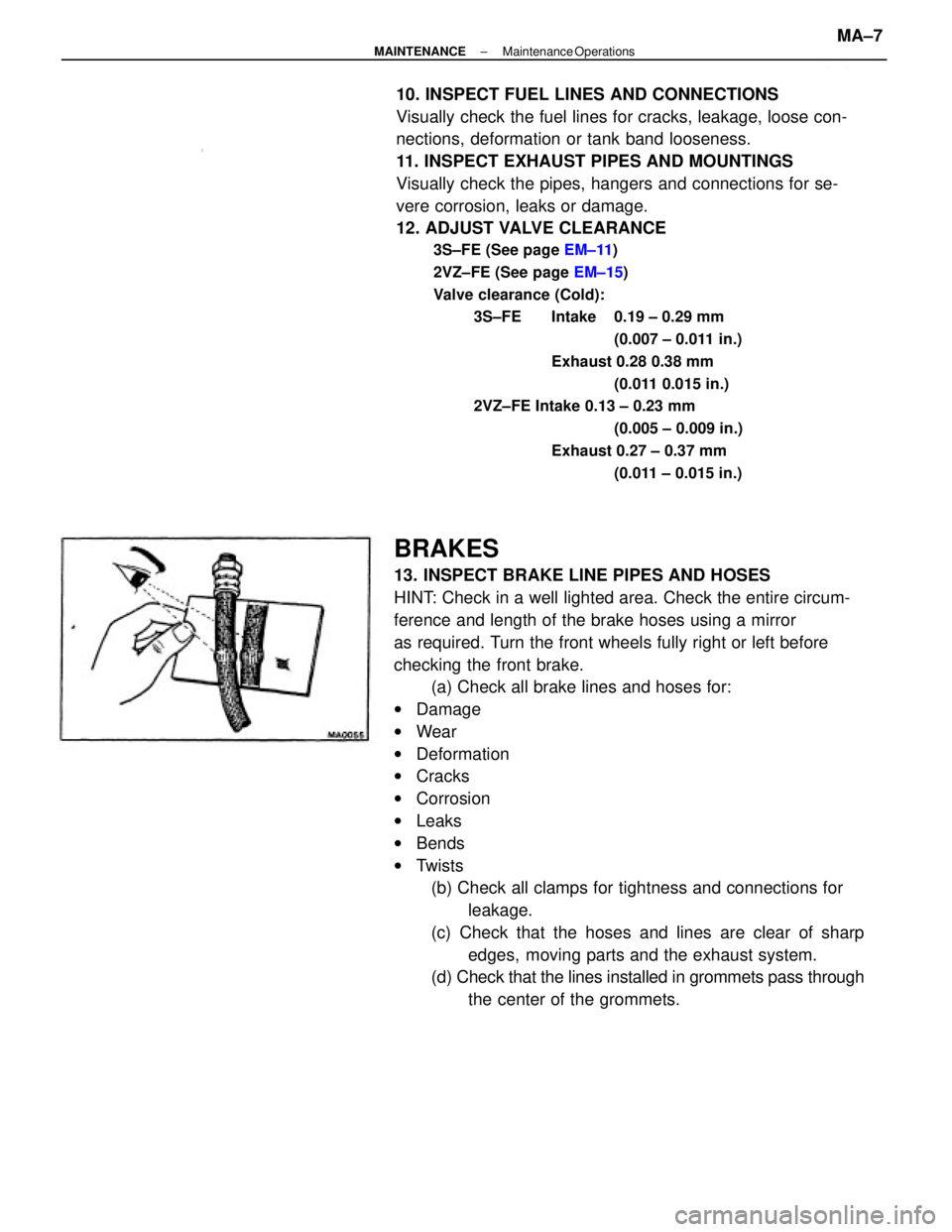
13. INSPECT BRAKE LINE PIPES AND HOSES
HINT: Check in a well lighted area. Check the entire circum-
ference and length of the brake hoses using a mirror
as required. Turn the front wheels fully right or left before
checking the front brake.
(a) Check all brake lines and hoses for:
wDamage
wWear
wDeformation
wCracks
wCorrosion
wLeaks
wBends
wTwists
(b) Check all clamps for tightness and connections for
leakage.
(c) Check that the hoses and lines are clear of sharp
edges, moving parts and the exhaust system.
(d) Check that the lines installed in grommets pass through
the center of the grommets. 10. INSPECT FUEL LINES AND CONNECTIONS
Visually check the fuel lines for cracks, leakage, loose con-
nections, deformation or tank band looseness.
11. INSPECT EXHAUST PIPES AND MOUNTINGS
Visually check the pipes, hangers and connections for se-
vere corrosion, leaks or damage.
12. ADJUST VALVE CLEARANCE
3S±FE (See page EM±11)
2VZ±FE (See page EM±15)
Valve clearance (Cold):
3S±FE Intake 0.19 ± 0.29 mm
(0.007 ± 0.011 in.)
Exhaust 0.28 0.38 mm
(0.011 0.015 in.)
2VZ±FE Intake 0.13 ± 0.23 mm
(0.005 ± 0.009 in.)
Exhaust 0.27 ± 0.37 mm
(0.011 ± 0.015 in.)
± MAINTENANCEMaintenance OperationsMA±7
Page 2112 of 2389
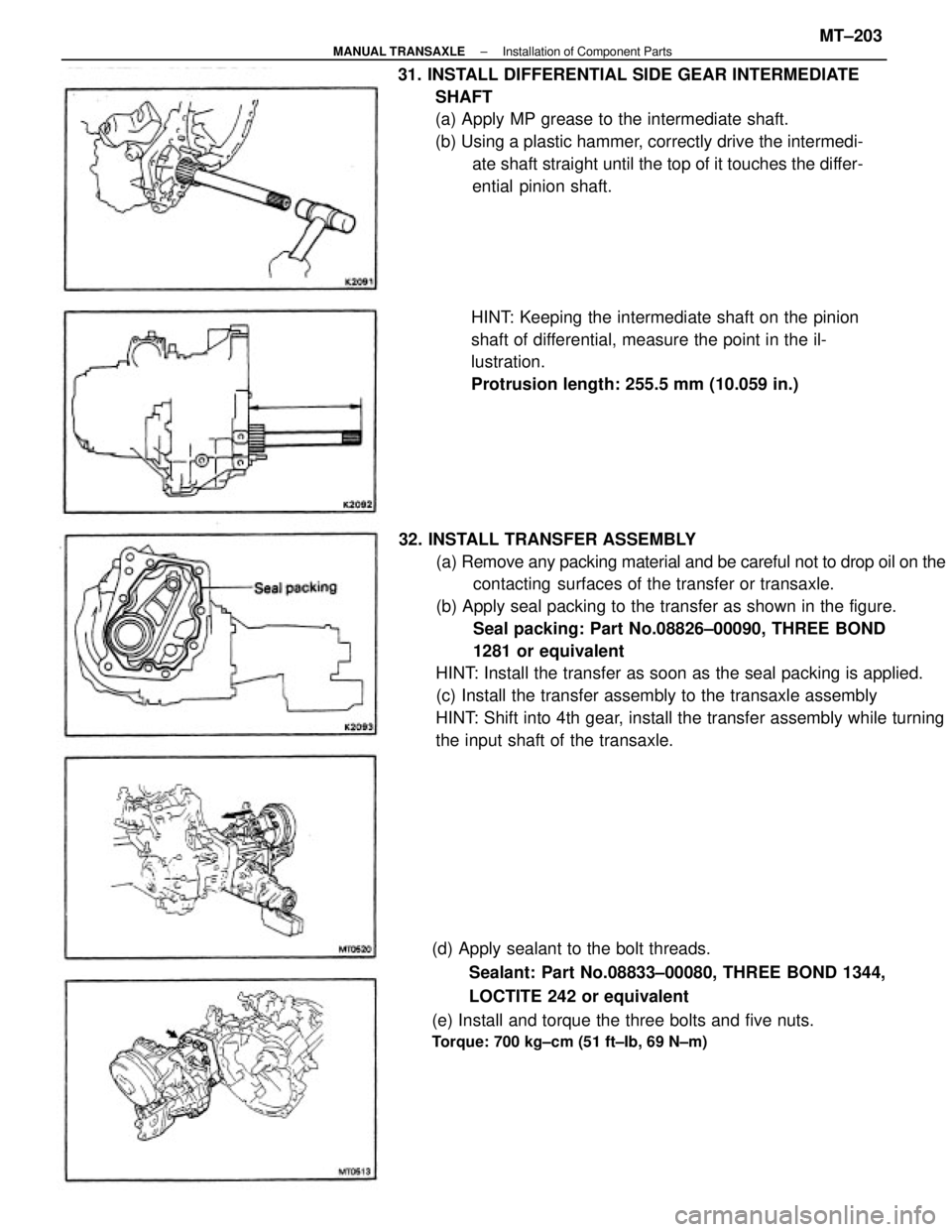
32. INSTALL TRANSFER ASSEMBLY
(a) Remove any packing material and be careful not to drop oil on the
contacting surfaces of the transfer or transaxle.
(b) Apply seal packing to the transfer as shown in the figure.
Seal packing: Part No.08826±00090, THREE BOND
1281 or equivalent
HINT: Install the transfer as soon as the seal packing is applied.
(c) Install the transfer assembly to the transaxle assembly
HINT: Shift into 4th gear, install the transfer assembly while turning
the input shaft of the transaxle. 31. INSTALL DIFFERENTIAL SIDE GEAR INTERMEDIATE
SHAFT
(a) Apply MP grease to the intermediate shaft.
(b) Using a plastic hammer, correctly drive the intermedi-
ate shaft straight until the top of it touches the differ-
ential pinion shaft.
(d) Apply sealant to the bolt threads.
Sealant: Part No.08833±00080, THREE BOND 1344,
LOCTITE 242 or equivalent
(e) Install and torque the three bolts and five nuts.
Torque: 700 kg±cm (51 ft±Ib, 69 N±m)
HINT: Keeping the intermediate shaft on the pinion
shaft of differential, measure the point in the il-
lustration.
Protrusion length: 255.5 mm (10.059 in.)
± MANUAL TRANSAXLEInstallation of Component PartsMT±203
Page 2125 of 2389
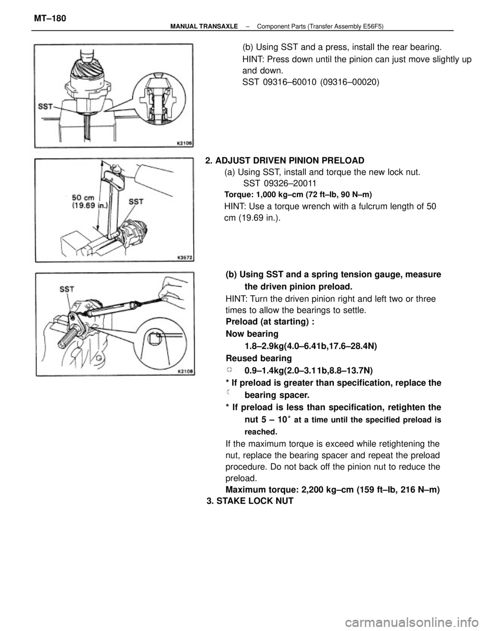
(b) Using SST and a spring tension gauge, measure
the driven pinion preload.
HINT: Turn the driven pinion right and left two or three
times to allow the bearings to settle.
Preload (at starting) :
Now bearing
1.8±2.9kg(4.0±6.41b,17.6±28.4N)
Reused bearing
0.9±1.4kg(2.0±3.1 1b,8.8±13.7N)
* If preload is greater than specification, replace the
bearing spacer.
* If preload is less than specification, retighten the
nut 5 ± 10
° at a time until the specified preload is
reached.
If the maximum torque is exceed while retightening the
nut, replace the bearing spacer and repeat the preload
procedure. Do not back off the pinion nut to reduce the
preload.
Maximum torque: 2,200 kg±cm (159 ft±Ib, 216 N±m)
3. STAKE LOCK NUT 2. ADJUST DRIVEN PINION PRELOAD
(a) Using SST, install and torque the new lock nut.
SST 09326±20011
Torque: 1,000 kg±cm (72 ft±Ib, 90 N±m)
HINT: Use a torque wrench with a fulcrum length of 50
cm (19.69 in.).(b) Using SST and a press, install the rear bearing.
HINT: Press down until the pinion can just move slightly up
and down.
SST 09316±60010 (09316±00020)
± MANUAL TRANSAXLEComponent Parts (Transfer Assembly E56F5)MT±180
Page 2150 of 2389
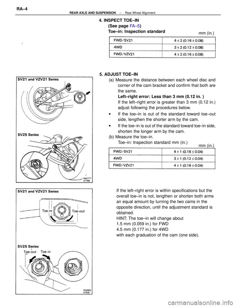
5. ADJUST TOE±IN
(a) Measure the distance between each wheel disc and
corner of the cam bracket and confirm that both are
the same.
Left±right error: Less than 3 mm (0.12 in. )
If the left±right error is greater than 3 mm (0.12 in.)
adjust following the procedures below.
wIf the toe±in is out of the standard toward toe±out
side, lengthen the shorter arm by the cam.
wIf the toe±in is out of the standard toward toe±in side,
shorten the longer arm by the cam.
(b) Measure the toe±in.
Toe±in: Inspection standard mm (in.)
If the left±right error is within specifications but the
overall toe±in is not, lengthen or shorten both arms
an equal amount by turning the two cams in the
opposite direction, until the adjustment standard is
obtained.
HINT: The toe±in will change about
1.5 mm (0.059 in.) for FWD
4.5 mm (0.177 in.) for 4WD
with each graduation of the cam (one side). 4. INSPECT TOE±IN
(See page FA ± 5)
Toe±in: Inspection standard
mm (in.) mm (in.)
± REAR AXLE AND SUSPENSIONRear Wheel AlignmentRA±4
Page 2171 of 2389
6. INSTALL INBOARD JOINT BOOT CLAMPS
NOTICE: The clamps of the outboard joint are smaller than
those of the inboard joint.
(a) Be sure the boot is on the shaft groove.
(b) Using a screwdriver, bend the band and lock it as
shown in the illustration.
8. INSTALL OUTBOARD JOINT BOOT CLAMPS
(a) Be sure the boot is on the shaft groove.
(b) In sure that the boot is not stretched or contracted
when drive shaft is at standard length.
Drive shaft length: 557.7 mm (21.957 In.) 7. INSTALL OUTBOARD JOINT BOOT
(a) Before install the boot, back in grease.
HINT: Use the grease supplied in the boot kit.
Grease capacity: 124 g (0.26 lb)
(b) Install the boot to the outboard joint. (b) Align the matchmarks placed before remove, and
install the inboard joint tulip to the drive shaft.
5. INSTALL INBOARD JOINT BOOT TO INBOARD JOINT
TULIP .
(c) Using a screwdriver, bend the band and lock it as
shown in the illustration.
± REAR AXLE AND SUSPENSIONRear Drive Shaft (4WD)RA±25