Page 1222 of 2389
12. SET TIMING BELT TENSIONER
(a) Place a plate washer between the tensioner and a block.
(b) Using a press, slowly press in the push rod using 100
± 1,000 kg (220 ± 2,205 ib, 981 ± 9,807 N) of pressure.
(c) Align the holes of the push rod and housing, pass a
1.27 mm hexagon wrench (sized 1.27 mm) through the
holes to keep the setting position of the push rod.
(d) Release the press.
(e) Install the dust boot to the tensioner. (g) Using SST, install and torque the bolt.
SST09249±63010 and 09278±54012
Torque: 760 kg±cm (55 ft±lb, 75 N±m)
HINT: Use a torque wrench with a fulcrum length of 340
mm (13.39 in.). (f) Using SST, align the knock pin hole of the camshaft with
the knock pin groove of the pulley and install the
knock pin.
SST 09278±54012
13. INSTALL TIMING BELT TENSIONER
(a) Install the tensioner with the two bolts.
Torque: 270 kg±cm (20 ft±lb, 26 N±m)
± ENGINE MECHANICALTiming Belt (2VZ±FE)EM±45
Page 1230 of 2389
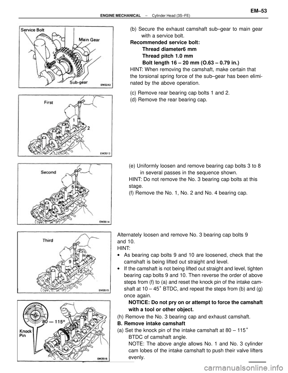
Alternately loosen and remove No. 3 bearing cap bolts 9
and 10.
HINT:
wAs bearing cap bolts 9 and 10 are loosened, check that the
camshaft is being lifted out straight and level.
wIf the camshaft is not being lifted out straight and level, tighten
bearing cap bolts 9 and 10. Then reverse the order of above
steps from (f) to (a) and reset the knock pin of the intake cam-
shaft at 10 ± 45° BTDC, and repeat the steps from (b) and (g)
once again.
NOTICE: Do not pry on or attempt to force the camshaft
with a tool or other object.
(h) Remove the No. 3 bearing cap and exhaust camshaft.
B. Remove intake camshaft
(a) Set the knock pin of the intake camshaft at 80 ± 115°
BTDC of camshaft angle.
NOTE: The above angle allows No. 1 and No. 3 cylinder
cam lobes of the intake camshaft to push their valve lifters
evenly.(b) Secure the exhaust camshaft sub±gear to main gear
with a service bolt.
Recommended service bolt:
Thread diameter6 mm
Thread pitch 1.0 mm
Bolt length 16 ± 20 mm (O.63 ± 0.79 in.)
HINT: When removing the camshaft, make certain that
the torsional spring force of the sub±gear has been elimi-
nated by the above operation.
(e) Uniformly loosen and remove bearing cap bolts 3 to 8
in several passes in the sequence shown.
HINT: Do not remove the No. 3 bearing cap bolts at this
stage.
(f) Remove the No. 1, No. 2 and No. 4 bearing cap.(c) Remove rear bearing cap bolts 1 and 2.
(d) Remove the rear bearing cap.
± ENGINE MECHANICALCylinder Head (3S±FE)EM±53
Page 1238 of 2389
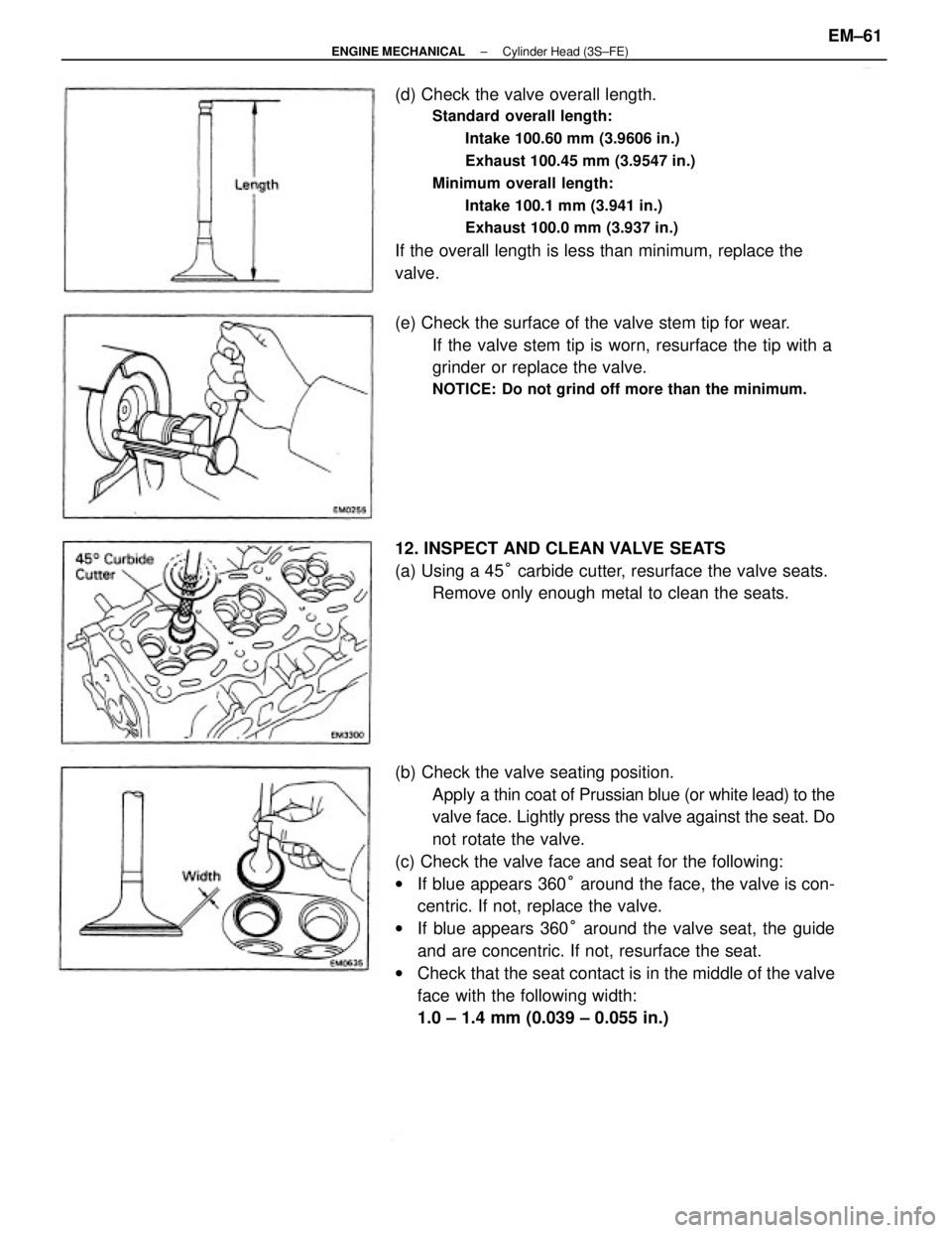
(b) Check the valve seating position.
Apply a thin coat of Prussian blue (or white lead) to the
valve face. Lightly press the valve against the seat. Do
not rotate the valve.
(c) Check the valve face and seat for the following:
wIf blue appears 360° around the face, the valve is con-
centric. If not, replace the valve.
wIf blue appears 360° around the valve seat, the guide
and are concentric. If not, resurface the seat.
wCheck that the seat contact is in the middle of the valve
face with the following width:
1.0 ± 1.4 mm (0.039 ± 0.055 in.) (d) Check the valve overall length.
Standard overall length:
Intake 100.60 mm (3.9606 in.)
Exhaust 100.45 mm (3.9547 in.)
Minimum overall length:
Intake 100.1 mm (3.941 in.)
Exhaust 100.0 mm (3.937 in.)
If the overall length is less than minimum, replace the
valve.
(e) Check the surface of the valve stem tip for wear.
If the valve stem tip is worn, resurface the tip with a
grinder or replace the valve.
NOTICE: Do not grind off more than the minimum.
12. INSPECT AND CLEAN VALVE SEATS
(a) Using a 45° carbide cutter, resurface the valve seats.
Remove only enough metal to clean the seats.
± ENGINE MECHANICALCylinder Head (3S±FE)EM±61
Page 1239 of 2389
13. INSPECT VALVE SPRINGS
(a) Using a steel square, measure the squareness of the valve
spring.
Maximum squareness: 2.0 mm (0.075 in.)
If squareness is greater than maximum, replace the valve
spring.
(b) Using calipers, measure the free length of the valve
spring.
Free length: 45.0 mm (1.772 in.)
If the free length is not as specified, replace the valve
spring. (d) Hand±lap the valve and valve seat with an abrasive
compound.
(e) After hand±lapping, clean the valve and valve seat. If not, correct the valve seats as follows:
(1) If the seating is too high on the valve face, use 30°
and 45° cutters to correct the seat.
(2) If the seating is too low on the valve face, use 75°
and 45° cutters to correct the seat.
± ENGINE MECHANICALCylinder Head (3S±FE)EM±62
Page 1240 of 2389
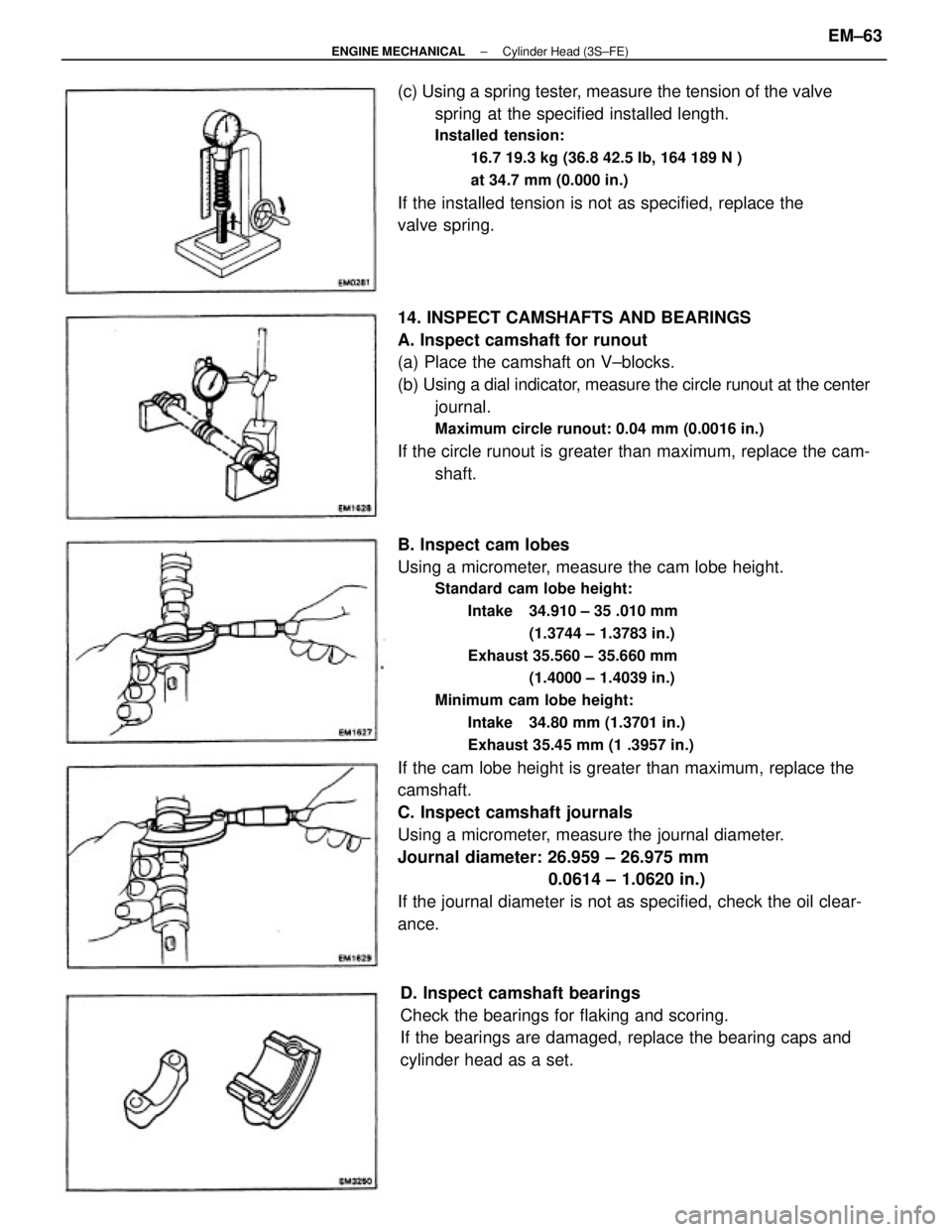
B. Inspect cam lobes
Using a micrometer, measure the cam lobe height.
Standard cam lobe height:
Intake 34.910 ± 35 .010 mm
(1.3744 ± 1.3783 in.)
Exhaust 35.560 ± 35.660 mm
(1.4000 ± 1.4039 in.)
Minimum cam lobe height:
Intake 34.80 mm (1.3701 in.)
Exhaust 35.45 mm (1 .3957 in.)
If the cam lobe height is greater than maximum, replace the
camshaft.
C. Inspect camshaft journals
Using a micrometer, measure the journal diameter.
Journal diameter: 26.959 ± 26.975 mm
0.0614 ± 1.0620 in.)
If the journal diameter is not as specified, check the oil clear-
ance. 14. INSPECT CAMSHAFTS AND BEARINGS
A. Inspect camshaft for runout
(a) Place the camshaft on V±blocks.
(b) Using a dial indicator, measure the circle runout at the center
journal.
Maximum circle runout: 0.04 mm (0.0016 in.)
If the circle runout is greater than maximum, replace the cam-
shaft. (c) Using a spring tester, measure the tension of the valve
spring at the specified installed length.
Installed tension:
16.7 19.3 kg (36.8 42.5 Ib, 164 189 N )
at 34.7 mm (0.000 in.)
If the installed tension is not as specified, replace the
valve spring.
D. Inspect camshaft bearings
Check the bearings for flaking and scoring.
If the bearings are damaged, replace the bearing caps and
cylinder head as a set.
± ENGINE MECHANICALCylinder Head (3S±FE)EM±63
Page 1257 of 2389
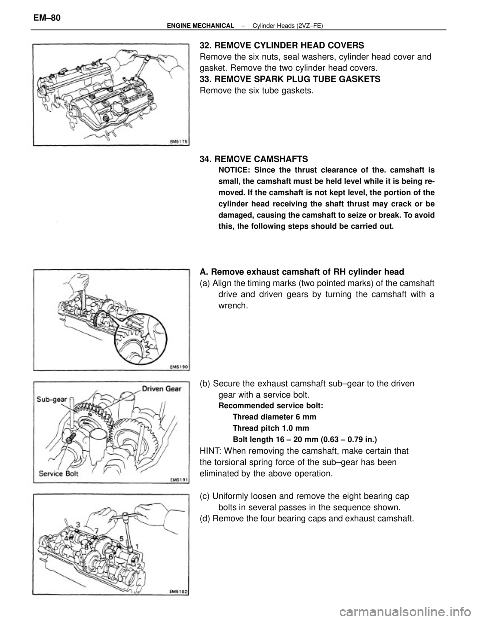
(b) Secure the exhaust camshaft sub±gear to the driven
gear with a service bolt.
Recommended service bolt:
Thread diameter 6 mm
Thread pitch 1.0 mm
Bolt length 16 ± 20 mm (0.63 ± 0.79 in.)
HINT: When removing the camshaft, make certain that
the torsional spring force of the sub±gear has been
eliminated by the above operation. 32. REMOVE CYLINDER HEAD COVERS
Remove the six nuts, seal washers, cylinder head cover and
gasket. Remove the two cylinder head covers.
33. REMOVE SPARK PLUG TUBE GASKETS
Remove the six tube gaskets.
34. REMOVE CAMSHAFTS
NOTICE: Since the thrust clearance of the. camshaft is
small, the camshaft must be held level while it is being re-
moved. If the camshaft is not kept level, the portion of the
cylinder head receiving the shaft thrust may crack or be
damaged, causing the camshaft to seize or break. To avoid
this, the following steps should be carried out.
A. Remove exhaust camshaft of RH cylinder head
(a) Align the timing marks (two pointed marks) of the camshaft
drive and driven gears by turning the camshaft with a
wrench.
(c) Uniformly loosen and remove the eight bearing cap
bolts in several passes in the sequence shown.
(d) Remove the four bearing caps and exhaust camshaft.
± ENGINE MECHANICALCylinder Heads (2VZ±FE)EM±80
Page 1258 of 2389
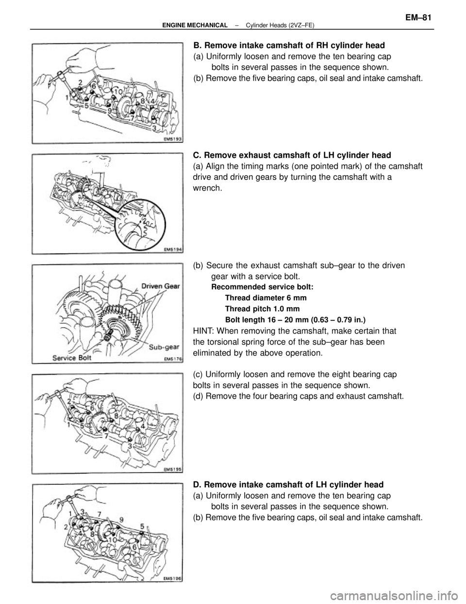
(b) Secure the exhaust camshaft sub±gear to the driven
gear with a service bolt.
Recommended service bolt:
Thread diameter 6 mm
Thread pitch 1.0 mm
Bolt length 16 ± 20 mm (0.63 ± 0.79 in.)
HINT: When removing the camshaft, make certain that
the torsional spring force of the sub±gear has been
eliminated by the above operation.
D. Remove intake camshaft of LH cylinder head
(a) Uniformly loosen and remove the ten bearing cap
bolts in several passes in the sequence shown.
(b) Remove the five bearing caps, oil seal and intake camshaft.B. Remove intake camshaft of RH cylinder head
(a) Uniformly loosen and remove the ten bearing cap
bolts in several passes in the sequence shown.
(b) Remove the five bearing caps, oil seal and intake camshaft.
C. Remove exhaust camshaft of LH cylinder head
(a) Align the timing marks (one pointed mark) of the camshaft
drive and driven gears by turning the camshaft with a
wrench.
(c) Uniformly loosen and remove the eight bearing cap
bolts in several passes in the sequence shown.
(d) Remove the four bearing caps and exhaust camshaft.
± ENGINE MECHANICALCylinder Heads (2VZ±FE)EM±81
Page 1266 of 2389
(b) Check the valve seating position.
Apply a thin coat of Prussian blue (or white lead) to the
valve face. Lightly press the valve against the seat. Do
not rotate the valve.
(c) Check the valve face and seat for the following:
wIf blue appears 360° around the face, the valve is con-
centric. If not, replace the valve.
wIf blue appears 360° around the valve seat, the guide
and face are concentric. If not, resurface the seat.
wCheck that the seat contact is in the middle of the valve
face with the following width:
1.0 ± 1.4 mm (0.039 ± 0.055 in.) (d) Check the valve overall length.
Standard overall length:
Intake 96.1 mm (3.783 in.)
Exhaust 96.2 mm (3.787 in.)
Minimum overall length:
Intake 95.6 mm (3.754 in.)
Exhaust 95.7 mm (3.768 in.)
If the overall length is less than minimum, replace the
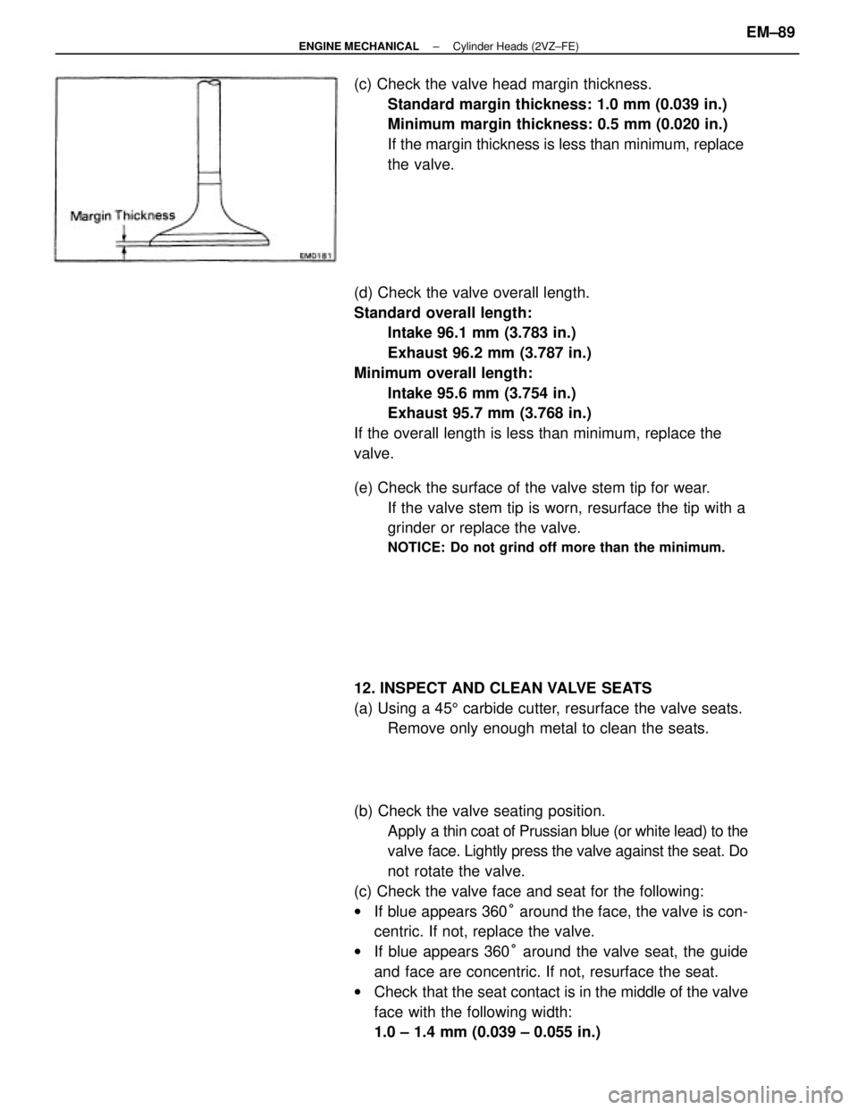
valve. (c) Check the valve head margin thickness.
Standard margin thickness: 1.0 mm (0.039 in.)
Minimum margin thickness: 0.5 mm (0.020 in.)
If the margin thickness is less than minimum, replace
the valve.
(e) Check the surface of the valve stem tip for wear.
If the valve stem tip is worn, resurface the tip with a
grinder or replace the valve.
NOTICE: Do not grind off more than the minimum.
12. INSPECT AND CLEAN VALVE SEATS
(a) Using a 455 carbide cutter, resurface the valve seats.
Remove only enough metal to clean the seats.
± ENGINE MECHANICALCylinder Heads (2VZ±FE)EM±89