Page 2260 of 2389

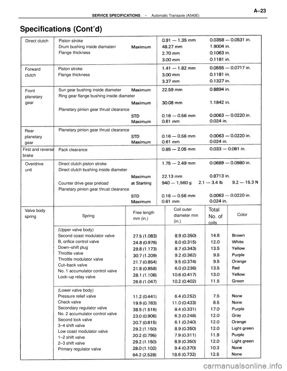
(Lower valve body)
Pressure relief valve
Check valve
Secondary regulator valve
No. 2 accumulator control valve
Second lock valve
3±4 shift valve
Low coast modulator valve
1±2 shift valve
2±3 shift valve
Primary regulator valve(Upper valve body)
Second coast modulator valve
B, orifice control valve
Down±shift plug
Throttle valve
Throttle modulator valve
Cut±back vaIve
No. 1 accumulator control valve
Lock±up relay valvePiston stroke
Drum bushing inside diamaterr
Flange thickness
Sun gear bushing inside diameter
Ring gear flange bushing inside diameter
Counter drive gear preload
Planetary pinion gear thrust clearanceDirect clutch piston stroke
Direct clutch bushing inside diameter Planetary pinion gear thrust clearancePlanetary pinion gear thrust clearance
Specifications (Cont'd)
Piston stroke
Flange thickness
Coil outer
diameter mm
(in.) Rear
planetary
gearFront
planetary
gear Forward
clutch
First and reverse
brake
Free length
mm (in.) Valve body
springOverdrive
unit
Total
No. of
coils Pack clearance Direct clutch
SpringColor
± SERVICE SPECIFICATIONSAutomatic Transaxle (A540E)A±23
Page 2261 of 2389
(Lower valve body)
Primary regulator valve
Secondary regulator valve
No. 2 accumulator control valve
Second lock valve
Low coast modulator valve
1±2 shift valve
2±3 shift valve
3±4 shift valve (Upper valve body)
Lock±up relay valve
Throttle modulator valve
Second coast modulator valve
Cut±back valve
No. 1 accumulator control valve
B, orifice contron valve
Pinion to side gear backlash
Side gear thrust washer thickness
Specifications (Cont'd)
Side bearing adjusting shim thicknessDrive pinion preload (at startin )
Total preload (at starting)Coil outer
diameter mm
(in.) Accumulator
springFree length
mm (in.) Valve body
retainerThickness
(mm (in.)
Total
No. of
coils Width
mm (in.) Height mm
(in.)
DifferentialRetainer
SpringColor
± SERVICE SPECIFICATIONSAutomatic Transaxle (A540E)A±24
Page 2265 of 2389
Driven pinion preload (at starting)
Total preload (at starting)
Ring gear backlash
Driven pinion bearing cage
Driven pinion preload (at starting)
New bearing
Reused bearing
Center differential side gear backlash
Center differential left side gear
thrust washer thickness
Center differential side gear thrust
clearance
Center differential right side gear
thrust washer thickness
Transfer clutch modulator valve
No. 2 low±high shift valve
No. 1 low±high shift valve Side bearing adjusting shim
thickness leont'dy
Specifications (Cont'd)
Transfer lower valve body springCoil outer
diameter mm
(in.) Differential end play
Free length
mm (in.) Differential
(cont'd)
Total
No. of
coils Transfer
Color
± SERVICE SPECIFICATIONSAutomatic Transaxle (A540H)A±28
Page 2269 of 2389
Wheel lateral runout
Tie rod end left±right error
Hub bearing axial direction play
Ball joint vertial play
Ball joint rotation condition
Drive shaft standard length
(FWD/SV21 /TOYOTA type/LH)
(FWD/SV21 /TOYOTA type/RH)
(FWD/SV21 /GKN type/LH)
(FWD/SV21 /GKN type/RH)
( FVIJD/VZV21)
(4WD/M/T/LH)
(4WD/A/T/LH)
(4WD/M/T/RH)
FRONT AXLE AND SUSPENSION
Specifications
Wheel angle
(FWD/SV21 and 4WD)
(FWD/VZV21)(FWD/SV21 and 4WD)
( FWD/VZV21)
Less than 3.0 mm/m (0.118 in./3.3 ft) (FWD/SV21 )
(4WD)
(F1ND/VZV21 )
Front axle
and suspensionChassis groung
clearance
Steering axis inclination Cold tire
inflation
pressure
Front wheel
alignment
Outside wheel (Max.)
Inside wheel (Max.)Adjustment STD
Inspection STD
Side slipCamber
Caster Toe±in
± SERVICE SPECIFICATIONSFront Axle and SuspensionA±31
Page 2276 of 2389
PS pump rotating torque
Steering rack runout
Control valve bearing preload
STEERING
Specifications
Steering effort
Rotor shaft bushing oil clearanceSteering wheel freeplay
Collar No. 1 outer diameter
Vane plate length Rotor and cam ring markMaximum rise of oil level
Oil pressure at idle speed
Vane plate to rotor groove clearance
Flow control valve spring lengthCollar No. 2 outer diameter
Support shim thickness
Drive belt tension Steering
column
Power steering
Total preloadVane plate
± SERVICE SPECIFICATIONSSteeringA±38
Page 2315 of 2389

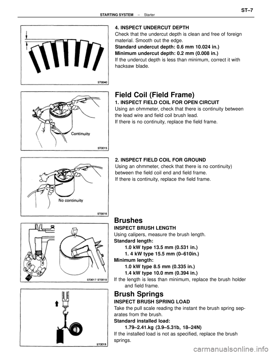
Brushes
INSPECT BRUSH LENGTH
Using calipers, measure the brush length.
Standard length:
1.0 kW type 13.5 mm (0.531 in.)
1. 4 kW type 15.5 mm (0±610in.)
Minimum length:
1.0 kW type 8.5 mm (0.335 in.)
1.4 kW type 10.0 mm (0.394 in.)
If the length is less than minimum, replace the brush holder
and field frame.
Brush Springs
INSPECT BRUSH SPRING LOAD
Take the pull scale reading the instant the brush spring sep-
arates from the brush.
Standard installed load:
1.79±2.41.kg (3.9±5.31b, 18±24N)
If the installed load is not as specified, replace the brush
springs.4. INSPECT UNDERCUT DEPTH
Check that the undercut depth is clean and free of foreign
material. Smooth out the edge.
Standard undercut depth: 0.6 mm 10.024 in.)
Minimum undercut depth: 0.2 mm (0.008 in.)
If the undercut depth is less than minimum, correct it with
hacksaw blade.
Field Coil (Field Frame)
1. INSPECT FIELD COIL FOR OPEN CIRCUIT
Using an ohmmeter, check that there is continuity between
the lead wire and field coil brush lead.
If there is no continuity, replace the field frame.
2. INSPECT FIELD COIL FOR GROUND
Using an ohmmeter, check that there is no continuity)
between the field coil end and field frame.
If there is continuity, replace the field frame.
± STARTING SYSTEMStarterST±7
Page 2337 of 2389

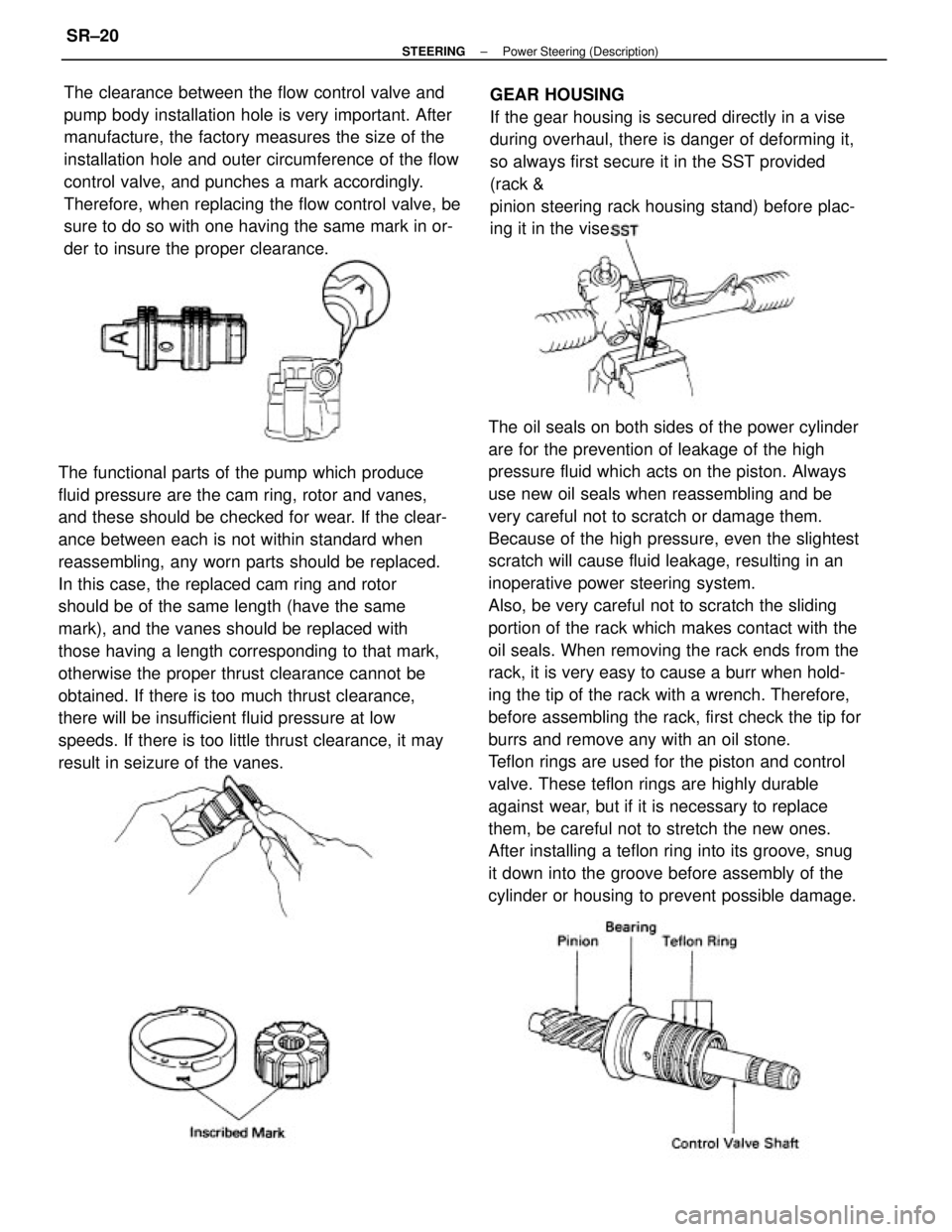
The oil seals on both sides of the power cylinder
are for the prevention of leakage of the high
pressure fluid which acts on the piston. Always
use new oil seals when reassembling and be
very careful not to scratch or damage them.
Because of the high pressure, even the slightest
scratch will cause fluid leakage, resulting in an
inoperative power steering system.
Also, be very careful not to scratch the sliding
portion of the rack which makes contact with the
oil seals. When removing the rack ends from the
rack, it is very easy to cause a burr when hold-
ing the tip of the rack with a wrench. Therefore,
before assembling the rack, first check the tip for
burrs and remove any with an oil stone.
Teflon rings are used for the piston and control
valve. These teflon rings are highly durable
against wear, but if it is necessary to replace
them, be careful not to stretch the new ones.
After installing a teflon ring into its groove, snug
it down into the groove before assembly of the
cylinder or housing to prevent possible damage. The functional parts of the pump which produce
fluid pressure are the cam ring, rotor and vanes,
and these should be checked for wear. If the clear-
ance between each is not within standard when
reassembling, any worn parts should be replaced.
In this case, the replaced cam ring and rotor
should be of the same length (have the same
mark), and the vanes should be replaced with
those having a length corresponding to that mark,
otherwise the proper thrust clearance cannot be
obtained. If there is too much thrust clearance,
there will be insufficient fluid pressure at low
speeds. If there is too little thrust clearance, it may
result in seizure of the vanes.The clearance between the flow control valve and
pump body installation hole is very important. After
manufacture, the factory measures the size of the
installation hole and outer circumference of the flow
control valve, and punches a mark accordingly.
Therefore, when replacing the flow control valve, be
sure to do so with one having the same mark in or-
der to insure the proper clearance.GEAR HOUSING
If the gear housing is secured directly in a vise
during overhaul, there is danger of deforming it,
so always first secure it in the SST provided
(rack &
pinion steering rack housing stand) before plac-
ing it in the vise.
± STEERINGPower Steering (Description)SR±20
Page 2355 of 2389
(MAIN POINTS OF REMOVAL AND
INSTALLATION)
1. DISCONNECT AND CONNECT PRESSURE LINE
Using SST, disconnect and connect the pressure line.
SST 09631±22020
HINT: When connecting, use a torque wrench with a ful-
crum length of 340 mm (13.39 in.).
3. REMOVE DRIVE BELT
(a) Loosen the adjusting bolt and the through bolt and
push the PS pump forward.
(b) Remove the drive belt. 2. DISCONNECT TIE ROD END RH
(a) Remove the cotter pin and nut.
(b) Using SST, disconnect the tie rod end RH.
SST 09610±55012
4. REMOVE PUMP BRACKET
(a) Remove the adjusting bolt.
(b) Remove the bolt and bracket.
5. REMOVE REAR PUMP STAY
Remove the two bolts and stay.
± STEERINGPower Steering (Power Steering Pump)SR±29