Page 2358 of 2389
(MAIN POINTS OF REMOVAL AND
INSTALLATION)
1. DISCONNECT AND CONNECT PRESSURE LINE
Using SST, disconnect and connect the pressure line.
SST 09631±22020
HINT: When connecting, use a torque wrench with a ful-
crum length of 340 mm (13.39 in.).
(b) Loosen the through bolt and push the PS pump for-
ward.
(c) Remove the drive belt.
4. REMOVE PS PUMP WITH PRESSURE TUBE
Remove the adjusting bolt and through bolt, then remove
PS pump from the lower side of vehicle body. 2. DISCONNECT TIE ROD END RH
(a) Remove the cotter pin and nut.
(b) Using SST, disconnect the tie rod end RH.
SST 09628±62011
3. REMOVE DRIVE BELT
(a) Loosen the adjusting bolt.
5. REMOVE PRESSURE TUBE
± STEERINGPower Steering (Power Steering Pump)SR±32
Page 2363 of 2389

INSPECTION OF POWER STEERING
PUMP
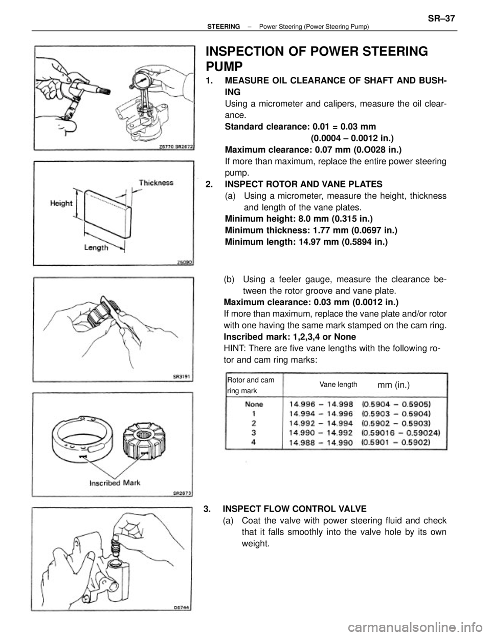
1. MEASURE OIL CLEARANCE OF SHAFT AND BUSH-
ING
Using a micrometer and calipers, measure the oil clear-
ance.
Standard clearance: 0.01 = 0.03 mm
(0.0004 ± 0.0012 in.)
Maximum clearance: 0.07 mm (0.O028 in.)
If more than maximum, replace the entire power steering
pump.
2. INSPECT ROTOR AND VANE PLATES
(a) Using a micrometer, measure the height, thickness
and length of the vane plates.
Minimum height: 8.0 mm (0.315 in.)
Minimum thickness: 1.77 mm (0.0697 in.)
Minimum length: 14.97 mm (0.5894 in.)
(b) Using a feeler gauge, measure the clearance be-
tween the rotor groove and vane plate.
Maximum clearance: 0.03 mm (0.0012 in.)
If more than maximum, replace the vane plate and/or rotor
with one having the same mark stamped on the cam ring.
Inscribed mark: 1,2,3,4 or None
HINT: There are five vane lengths with the following ro-
tor and cam ring marks:
3. INSPECT FLOW CONTROL VALVE
(a) Coat the valve with power steering fluid and check
that it falls smoothly into the valve hole by its own
weight.
Rotor and cam
ring markVane lengthmm (in.)
± STEERINGPower Steering (Power Steering Pump)SR±37
Page 2364 of 2389
(b) Check the flow control valve for leakage.
Close.one of the holes and apply compressed air [4
±5 kg/crn
2 (57 ± 71 psi, 392 ± 490 kPa)] into the oppo-
site side, and confirm that air does not come out from
the end hole.
4. INSPECT FLOW CONTROL SPRING
Using a scale, measure the free length of the spring.
Spring length: 36 ± 38 mm (1.42 ± 1.49 in.)
If not within specification, replace the spring. If necessary, replace the valve with one having the
same letter as inscribed on the front housing.
Inscribed mark: A,6,C,6, E or F
5. IF NECESSARY, REPLACE OIL SEAL
A
(a) Using a screwdriver, pry out the oil seal.
(b) Using a socket wrench and hammer, drive in a new
oil seal.
± STEERINGPower Steering (Power Steering PumpSR±38
Page 2387 of 2389

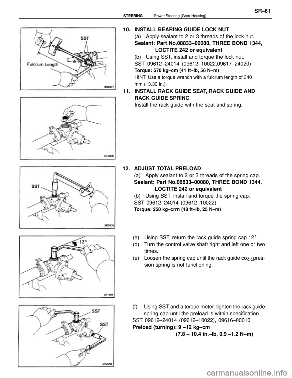
10. INSTALL BEARING GUIDE LOCK NUT
(a) Apply sealant to 2 or 3 threads of the lock nut.
Sealant: Part No.08833±00080, THREE BOND 1344,
LOCTITE 242 or equivalent
(b) Using SST, install and torque the lock nut.
SST 09612±24014 (09612±10022,09617±24020)
Torque: 570 kg±cm (41 ft±Ib, 56 N±m)
HINT: Use a torque wrench with a fulcrum length of 340
mm (13.39 in.).
11. INSTALL RACK GUIDE SEAT, RACK GUIDE AND
RACK GUIDE SPRING
Install the rack guide with the seat and spring.
12. ADJUST TOTAL PRELOAD
(a) Apply sealant to 2 or 3 threads of the spring cap.
Sealant: Part No.08833±00080, THREE BOND 1344,
LOCTITE 242 or equivalent
(b) Using SST, install and torque the spring cap.
SST 09612±24014 (09612±10022)
Torque: 250 kg±crrn (18 ft±Ib, 25 N±m)
(e) Using SST, return the rack guide spring cap 12°.
(d) Turn the control valve shaft right and left one or two
times.
(e) Loosen the spring cap until the rack guide co¿¿pres-
sion spring is not functioning.
(f) Using SST and a torque meter, tighten the rack guide
spring cap until the preload is within specification.
SST 09612±24014 (09612±10022), 09616±00010
Preload (turning): 9 ±12 kg±cm
(7.8 ± 10.4 in.±Ib, 0.9 ±1.2 N±m)
± STEERINGPower Steering (Gear Housing)SR±61
Page 2388 of 2389

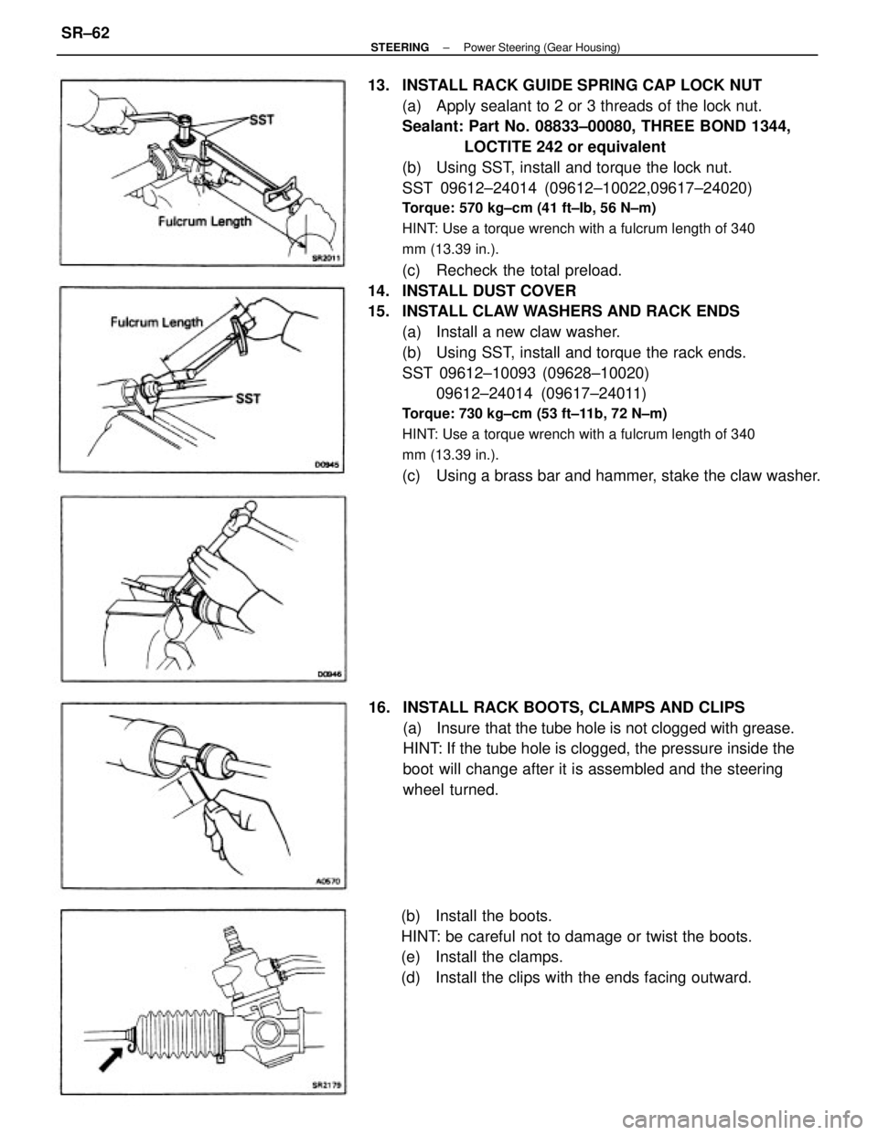
13. INSTALL RACK GUIDE SPRING CAP LOCK NUT
(a) Apply sealant to 2 or 3 threads of the lock nut.
Sealant: Part No. 08833±00080, THREE BOND 1344,
LOCTITE 242 or equivalent
(b) Using SST, install and torque the lock nut.
SST 09612±24014 (09612±10022,09617±24020)
Torque: 570 kg±cm (41 ft±Ib, 56 N±m)
HINT: Use a torque wrench with a fulcrum length of 340
mm (13.39 in.).
(c) Recheck the total preload.
14. INSTALL DUST COVER
15. INSTALL CLAW WASHERS AND RACK ENDS
(a) Install a new claw washer.
(b) Using SST, install and torque the rack ends.
SST 09612±10093 (09628±10020)
09612±24014 (09617±24011)
Torque: 730 kg±cm (53 ft±11b, 72 N±m)
HINT: Use a torque wrench with a fulcrum length of 340
mm (13.39 in.).
(c) Using a brass bar and hammer, stake the claw washer.
16. INSTALL RACK BOOTS, CLAMPS AND CLIPS
(a) Insure that the tube hole is not clogged with grease.
HINT: If the tube hole is clogged, the pressure inside the
boot will change after it is assembled and the steering
wheel turned.
(b) Install the boots.
HINT: be careful not to damage or twist the boots.
(e) Install the clamps.
(d) Install the clips with the ends facing outward.
± STEERINGPower Steering (Gear Housing)SR±62
Page 2389 of 2389
17. INSTALL TIE ROD ENDS
(a) Screw the lock nuts and tie rod ends onto the rack
ends until the matchmarks are aligned.
(b) After adjusting toe±in, torque the lock nuts.
Torque: 570 kg±cm (41 ft±Ib, 56 N±m)
(b) Using SST, install and torque the tubes.
SST 09633±00020
Torque: 200 kg±cm (14 ft±Ib, 20 N±m)
HINT: Use a torque wrench with a fulcrum length of 300
mm (11.81 in.). 18. INSTALL RIGHT AND LEFT TURN PRESSURE TUBES
(a) Install new union seats as shown.
± STEERINGPower Steering (Gear Housing)SR±63