Page 1267 of 2389
13. INSPECT VALVE SPRINGS
(a) Using a steel square, measure the squareness of the valve
spring.
Maximum squareness: 2.0 mm (0.075 in.)
if squareness is greater than maximum, replace the valve
spring.
(b) Using calipers, measure the free length of the valve
spring.
Free length: 42.6 mm (1.677 in.)
If the free length is not as specified, replace the valve
spring. If not, correct the valve seats as follows:
111 If the seating is too high on the valve face, use
30° and 45° cutters to correct the seat.
(d) Hand±lap the valve and valve seat with an abrasive
compound.
After hand±lapping, clean the valve and valve seat. (2) If the seating is too low on the valve face, use
60° and 45° cutters to correct the seat.
± ENGINE MECHANICALCylinder Heads (2VZ±FE)EM±90
Page 1268 of 2389

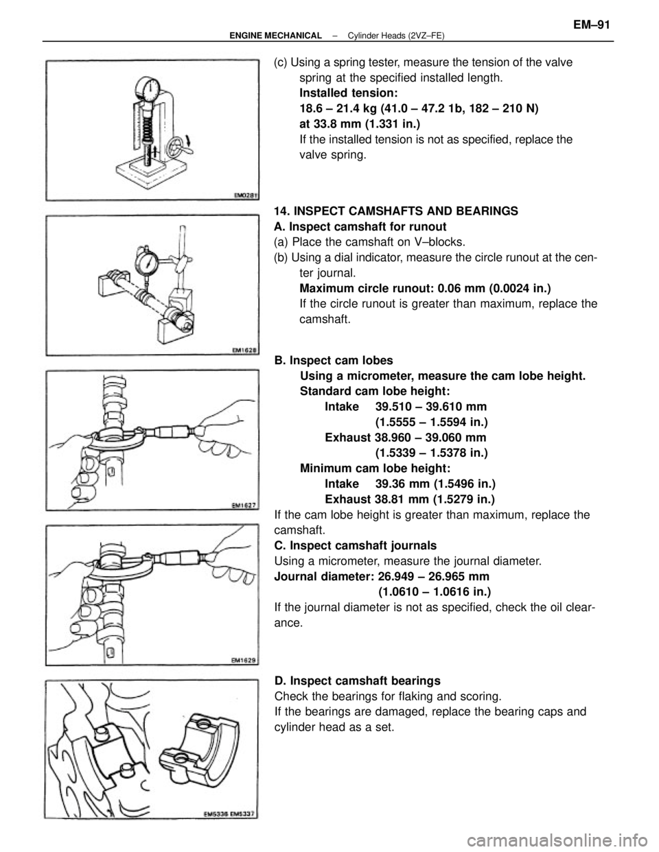
B. Inspect cam lobes
Using a micrometer, measure the cam lobe height.
Standard cam lobe height:
Intake 39.510 ± 39.610 mm
(1.5555 ± 1.5594 in.)
Exhaust 38.960 ± 39.060 mm
(1.5339 ± 1.5378 in.)
Minimum cam lobe height:
Intake 39.36 mm (1.5496 in.)
Exhaust 38.81 mm (1.5279 in.)
If the cam lobe height is greater than maximum, replace the
camshaft.
C. Inspect camshaft journals
Using a micrometer, measure the journal diameter.
Journal diameter: 26.949 ± 26.965 mm
(1.0610 ± 1.0616 in.)
If the journal diameter is not as specified, check the oil clear-
ance. 14. INSPECT CAMSHAFTS AND BEARINGS
A. Inspect camshaft for runout
(a) Place the camshaft on V±blocks.
(b) Using a dial indicator, measure the circle runout at the cen-
ter journal.
Maximum circle runout: 0.06 mm (0.0024 in.)
If the circle runout is greater than maximum, replace the
camshaft. (c) Using a spring tester, measure the tension of the valve
spring at the specified installed length.
Installed tension:
18.6 ± 21.4 kg (41.0 ± 47.2 1b, 182 ± 210 N)
at 33.8 mm (1.331 in.)
If the installed tension is not as specified, replace the
valve spring.
D. Inspect camshaft bearings
Check the bearings for flaking and scoring.
If the bearings are damaged, replace the bearing caps and
cylinder head as a set.
± ENGINE MECHANICALCylinder Heads (2VZ±FE)EM±91
Page 1361 of 2389

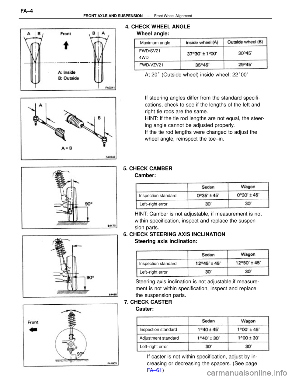
If steering angles differ from the standard specifi-
cations, check to see if the lengths of the left and
right tie rods are the same.
HINT: If the tie rod lengths are not equal, the steer-
ing angle cannot be adjusted properly.
If the tie rod lengths were changed to adjust the
wheel angle, reinspect the toe±in.
HINT: Camber is not adjustable, if measurement is not
within specification, inspect and replace the suspen-
sion parts.
6. CHECK STEERING AXIS INCLINATION
Steering axis inclination:
Steering axis inclination is not adjustable,if measure-
ment is not within specification, inspect and replace
the suspension parts.
7. CHECK CASTER
Caster:
If caster is not within specification, adjust by in-
creasing or decreasing the spacers. (See page
FA±61) At 20° (Outside wheel) inside wheel: 22°00' 4. CHECK WHEEL ANGLE
Wheel angle:
5. CHECK CAMBER
Camber:
Adjustment standard Inspection standard Inspection standard
Inspection standard FWD/SV21
4WDMaximum angle
Left±right error
Left±right error Left±right error FWD/VZV21
± FRONT AXLE AND SUSPENSIONFront Wheel AlignmentFA ± 4
Page 1363 of 2389
HINT: Insure that the lengths of the left and right
tie rod ends length are the same.
Tie rod end length left±right error:
Less than 1.5 mm (0.059 in.)
(d) Torque the tie rod end lock nuts.
Torque: 570 kg±cm (41 ft±lb , 56 N±M)
(e) Place the boot on the seat and clamp it.
HINT: Insure that the boots are not twisted.(e) Turn the left and right tie rod ends an equal amount to
adjust the toe±in.
Adjustment standard: 1 + 1 mm (0.04 + 0.04 in.)
10. INSPECT SIDE SLIP (REFERENCE ONLY)
Side slip: Less than 3.0 mm/m (0.118 in./3.3 ft)
± FRONT AXLE AND SUSPENSIONFront Wheel AlignmentFA ± 6
Page 1381 of 2389
7±2. (GKN TYPE)
ASSEMBLE BOOT CLAMPS TO BOTH BOOT
(a) Be sure the boot (large side) is on shaft groove.
(b) Using a boot clamp tool, place pincer jaws in closing
hooks of large clamp.
(c) Secure clamp by drawing closing hooks together. (c) Insure that the boot is no stretched or contracted
when the drive shaft is at standard length.
Drive shaft length:
LH 558.7
+ 5.0 mm (21.996 + 0.197 in.)
R H 845.2
+ 5.0 mm (33.276 + 0.197 in.) 7.(TOYOTA TYPE)
INSTALL BOOT CLAMPS TO BOTH BOOT
(a) Be sure the boot is on the shaft groove.
(b) Bend the band and lock it as shown.
(e) Be sure the boot (small side) is on the shaft
groove.
(f) Using a boot clamp tool, tighten the clamp. (d) Check that the clamp at closed position is the
same as in the illustration.
± FRONT AXLE AND SUSPENSIONFront Drive Shaft (FWD SV21 )FA±24
Page 1382 of 2389
Insure that the boot is no stretched or contracted
when the drive shaft is at standard length.
Drive shaft length:
LH 652.0
+ 6.0 mm (25.669 + 0:236 in.)
R H 937.0
+ 6.0 mm (36.890 + 0.236 in.)
± FRONT AXLE AND SUSPENSIONFront Drive Shaft (FWD SV21)FA±25
Page 1392 of 2389
5. ASSEMBLE INBOARD JOINT
(a) Align the nnatchmarks placed before disassembly.
(b) Using a brass bar and hammer, tap the inboard joint
onto the drive shaft.
NOTICE: Make sure that the brass bar is touching the inner
race, and not the cage.
(c) Remove the bolts, nuts and washers.
7. ASSEMBLE BOOT CLAMPS TO BOTH BOOTS
(a) Be sure the boot is on the shaft groove.
(b) Insure that the boot is not stretched or contracted when
the drive shaft is at standard length.
Drive shaft length: 406 mm (15.98 in.) 6. ASSEMBLE INBOARD JOINT BOOT TO INBOARD
JOINT
Pack in grease to the inboard tulip and boot.
HINT: Use the grease supplied in the boot kit.
Grease capacity: 90 ± 100 g (0.20 ± 0.22 Ib)(d) Using snap ring pliers, install a new snap ring.
NOTICE: Work carefully not to come off the outer race.
(c) Bend the band and lock it as shown.
± FRONT AXLE AND SUSPENSIONFront Drive Shaft (FWD VZV21)FA±35
Page 1405 of 2389
(c) Insure that the boot is not stretched or contracted
when the drive shaft is at standard length.
Drive shaft standard length:
(M/T) LH 512.5
+ 5.0 mm (20.177 + 0.197 in.)
R H 512.5
+ 5.0 mm (20.177 + 0.197 in.)
(A/T) LH 512.5
+ 5.0 mm (20.177 + 0.197 in.)
R H 515.7
+ 5.0 mm (20.303 + 0.197 in.)
(d) Install the snap ring. 6. ASSEMBLE BOOT CLAMPS
(a) Be sure the boot is on the shaft groove.
(b) Using a screwdriver, bend the band and lock it as
shown in the illustration. (b) Align the matchmarks placed before remove, and
install the inboard joint tulip to the drive shaft.
(e) Install the boot to the inboard joint tulip.
± FRONT AXLE AND SUSPENSIONFront Drive Shaft (4WD)FA±48