1986 TOYOTA CAMRY V20 length
[x] Cancel search: lengthPage 903 of 2389

(c) In the event pressure cannot be adjusted by the spring
length, raise or lower the valve body.
Low pressure ± Lower
High pressure ± Raise
HINT: 1 mm (0.04 in.) displacement of the valve body
changes the fluid pressure about 7.2 kg /cm
2 (102.4 psi,
706 kPa).
(d) Torque the nuts.
Torque: 130 kg±cm (9 ft±lb, 13 N±m)
(e) Adjust the fluid pressure by changing the spring
length again.
If it cannot be adjusted, replace the valve assembly.(b) Tighten the nuts.
Torque: 260 kg±cm (19 ft±Ib, 25 N±m)
± BRAKE SYSTEMLSPVBR±52
Page 905 of 2389

2. CONNECT BRAKE TUBES
Using SST, connect the brake tubes.
SST 09751±36011
Torque: 155 kg±cm (11 ft±Ib, 15 N±m)
3. FILL BRAKE RESERVOIR WITH BRAKE FLUID AND
BLEED BRAKE SYSTEM
(See page BR±7)
4. CHECK FOR FLUID LEAKAGE
5. CHECK AND ADJUST FLUID PRESSURE
(See page BR±50)
6. REMOVE SST AND BLEED BRAKE SYSTEM
SST 09709±29017
7. CHECK FOR FLUID LEAKAGE(c) Set spring length A to initial set length and tempo-
rarily tighten the adjusting bolt lock nut.
Initial set length: 2VZ±FE 167.6 mm (6.598 in.)
Others 166.9 mm (6.571 in.)
± BRAKE SYSTEMLSPVBR±54
Page 967 of 2389

3. INSPECT SLIP RINGS
(a) Check that the slip rings are not rough or scored.
If rough or scored, replace the rotor.
(b) Using calipers, measure the slip ring diameter.
Standard diameter. 14.2 ±14.4 mm
(0.559 ± 0.567 in.)
Minimum diameter 12.8 mm (0.504 in.)
If the diameter is less than minimum, replace the rotor.
Brushes
1. INSPECT EXPOSED BRUSH LENGTH
Using a scale, measure the exposed brush length.
Standard exposed length: 10.5 mm (0.413 in,)
Minimum exposed length: 1 .5 mm (0.069 in.)
If the exposed length is less than minimum, replace the
brushes.
Stator
1. INSPECT STATOR FOR OPEN CIRCUIT
Using an ohmmeter, check that there is continuity between
the coil leads.
If there is no continuity, replace the drive end frame assem-
bly.2. INSPECT ROTOR FOR GROUND
Using an ohmmeter, check that there is no continuity
between the slip ring and rotor.
If there is continuity, replace the rotor.
2. INSPECT STATOR FOR GROUND
Using an ohmmeter, check that there is no continuity be-
tween the coil lead and drive end frame.
If there is continuity, replace the drive end frame assembly.
± CHARGING SYSTEMAlternatorCH±9
Page 968 of 2389

Rectifiers (Rectifier Holder)
1. INSPECT POSITIVE RECTIFIER
(a) Connect the ohmmeter positive (+) probe to each rectifier
terminal and the negative (±) probe to the positive (+) ter-
minal, and check that there is no continuity.
(b) Reverse the ohmmeter probes, and check that there is con-
tinuity.
If continuity is not as specified, replace the rectifier holder.
2. INSPECT NEGATIVE RECTIFIER
(a) Connect the ohmmeter positive (+) probe to each rectifier
terminal and the negative (±) probe to each negative (±)
terminal, check that there is continuity.
(b) Reverse the ohmmeter probes, and checK that there is no
continuity.
If continuity is not as specified, replace the rectifier holder. (c) Solder the brush wire to the brush holder at specified
exposed length.
Exposed length: 10.5 mm (a.413 in.)
(d) Check that the brush moves smoothly in the brush
holder.
(e) Cut off the excess wire.
(f) Apply insulation paint to the soldered point. 2. IF NECESSARY, REPLACE BRUSHES
(a) Unsolder and remove the brush and spring.
(b) Run the wire of a new brush through the hole in the
brush holder, and insert the spring and brush into the
brush holder.
Bearings
1. INSPECT FRONT BEARING
Check that the bearing is not rough or worn.
± CHARGING SYSTEMAlternatorCH±10
Page 1022 of 2389

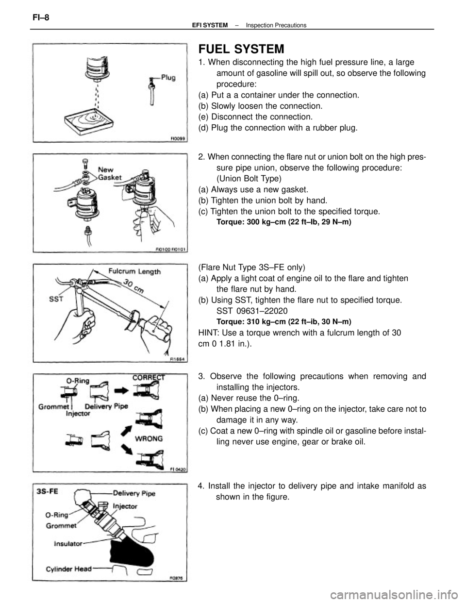
FUEL SYSTEM
1. When disconnecting the high fuel pressure line, a large
amount of gasoline will spill out, so observe the following
procedure:
(a) Put a a container under the connection.
(b) Slowly loosen the connection.
(e) Disconnect the connection.
(d) Plug the connection with a rubber plug.
(Flare Nut Type 3S±FE only)
(a) Apply a light coat of engine oil to the flare and tighten
the flare nut by hand.
(b) Using SST, tighten the flare nut to specified torque.
SST 09631±22020
Torque: 310 kg±cm (22 ft±ib, 30 N±m)
HINT: Use a torque wrench with a fulcrum length of 30
cm 0 1.81 in.). 2. When connecting the flare nut or union bolt on the high pres-
sure pipe union, observe the following procedure:
(Union Bolt Type)
(a) Always use a new gasket.
(b) Tighten the union bolt by hand.
(c) Tighten the union bolt to the specified torque.
Torque: 300 kg±cm (22 ft±Ib, 29 N±m)
3. Observe the following precautions when removing and
installing the injectors.
(a) Never reuse the 0±ring.
(b) When placing a new 0±ring on the injector, take care not to
damage it in any way.
(c) Coat a new 0±ring with spindle oil or gasoline before instal-
ling never use engine, gear or brake oil.
4. Install the injector to delivery pipe and intake manifold as
shown in the figure.
± EFI SYSTEMInspection PrecautionsFI±8
Page 1180 of 2389

The 3S±FE engine is an in±line 4±cylinder engine with the cylinders numbered 1 ± 2 ± 3 ± 4 from the
front.
The crankshaft is supported by 5 bearing inside the crankcase. These bearing are made of aluminum
alloy.
The crankshaft is integrated with 8 weights for balance. Oil holes are placed in the center of the crank-
shaft to supply oil to the connecting rods, bearing, pistons and other components.
This engine's ignition order is 1 ± 3 ± 4 ± 2. The cylinder head is made of aluminum alloy, with a cross
flow type intake and exhaust layout and with pent±roof type combustion chambers. The spark plugs are
located in the center of the combustion chamber.
The intake manifold has 8 independent long ports and utilizes the inertial supercharging effect to im-
prove engine torque at low and medium speeds.
Exhaust and intake valves are equipped with irregular pitch springs made of special valve spring carbon
steel which are capable of functioning no matter what the engine speed.
The intake side camshaft is driven by a timing belt, and a gear on the intake side camshaft engages with
a gear on the exhaust side camshaft to drive it. The cam journal is supported at 5 places between the
valve lifters of each cylinder and on the front end of the cylinder head. Lubrication of the cam journal and
gear is accomplished by oil being supplied through the oiler port in the center of the camshaft.
Adjustment of the valve clearance is done by means of outer shim type system, in which valve adjusting
shims are located above the valve lifters. This permits replacement of the shims without removal of the
camshafts.
The resin timing belt cover is made of 2 pieces. A service hole is provided in the No. 1 belt cover for ad-
justing the timing belt tension.
Piston are made of high temperature±resistant aluminum alloy, and a depression is built into the piston
head to prevent interference with the valves.
Piston pins are the semi±floating type, with the pins fastened to the connecting rods by pressure fitting,
allowing the pistons and pins to float.
The No. 1 compression ring is made of steel and the No. 2 compression ring is made of cast iron. The oil
ring is made of a combination of steel and stainless steel. The outer diameter of each piston ring is
slightly larger than the diameter of the piston and the flexibility of the rings allows them to hug the cylin-
der walls when they are mounted on the piston rings No. 1 and No. 2 work to prevent gas leakage from
the cylinder and oil ring works to clear oil off the cylinder walls to prevent it from entering the combustion
chambers.
The cylinder block is made of cast iron. It has 4 cylinders which are approximately 2 times the length of
the piston stroke. The top of the cylinders is closed off by the cylinder head and the lower end of the cyl-
inders becomes the crankcase, in which the crankshaft is installed. In .addition, the cylinder block con-
tains a water jacket, through which coolant is pumped to cool the cylinders.
The oil pan is bolted onto the bottom of the cylinder block. The oil pan is an oil reservoir made of
pressed steel shoot. A dividing plate is included inside the oil pan to keep sufficient oil in the bottom of
the pan even when the vehicle is tilted. This dividing plate also prevents the oil from making waves when
the vehicle is topped suddenly and thus shifting the oil away from the oil pump suction pipe.
± ENGINE MECHANICALDescription (3S±FE)EM±3
Page 1182 of 2389

The 2VZ±FE engine has 6 cylinder in a V arrangement at bank of 60°. From the front of the RH bank cylin-
ders are numbered 1 ± 3 ± 5, and from the front of the LH bank cylinders are numbered 2 ± 4 ±r 6. The crankshaft is
supported by 4 bearings inside the crankcase. These bearing are made of copper and lead alloy.
The crankshaft is integrated with 5 weights for balance. Oil holes are placed in the center of the crankshaft for sup-
plying oil to the connecting rods, pistons and other components.
This engine's ignition order is 1 ± 2 ± 3 ± 4 ± 5 ± 6. The cylinder head is made of aluminum alloy, with a cross flow
type intake and exhaust layout and with pent±roof type combustion chambers. The spark plugs are located in the
center of the combustion chambers.
At,the front and rear of the intake port of the intake manifold, a water passage has been provided which connects
the RH and LH cylinder heads.
Exhaust and intake valves are equipped with irregular pitch springs made of special valve spring carbon steel which
are capable of functioning no matter what the engine speed.
The RH and LH intake camshaft are driven by a single timing belt, and a gear on the intake side camshaft engages
with a gear on the exhaust side camshaft to drive it. The cam journal is supported at 5 (intake) or 4
(exhaust) places between the valve liters of each cylinder and on the front end of the cylinder head. Lubrication of
the cam journals and gears is accomplished by oil being supplied through the oiler port in the center of the camshaft.
Adjustment of the valve clearance is done by means of outer shim type system, in which valve adjusting shims are
located above the valve lifters. The permits replacement of the shims without removal of the camshafts.
The timing belt cover is composed of resin type No. 2 and No. 1 above and below the RH mounting bracket.
Piston are made high temperature±resistant aluminum alloy, and a depression is built into the piston head to prevent
interference with the valves.
Piston pins are the semi±floating type, with the pins fastened to the connecting rods by pressure fitting, allowing the
pistons and pins to float.
The No. 1 compression ring is made of steel and the No. 2 compression ring is made±of cast iron. The oil ring is
made of a combination of steel and stainless steel. The outer diameter of each piston ring is slightly larger than the
diameter of the piston and the flexibility of the rings allows them to hug the cylinder walls when they are mounted on
the piston. Compression rings No. 1 and No. 2 work to prevent gas leakage from the cylinder and oil ring works to
clear oil off the cylinder walls to prevent it from entering the combustion chambers.
The cylinder block is made of cast iron with a bank angle of 60°. It has 6 cylinders which are approximately 2
times the length of the piston stroke. The top of the cylinders is closed off by the cylinder heads and the lower end of
the cylinders becomes the crankcase, in which the crankshaft is installed. In addition, the cylinder block contains a
water jacket, through which coolant is pumped to cool the cylinders.
The oil pan is bolted onto the bottom of the cylinder block. The oil pan is an oil reservoir made of pressed steel
sheet. A dividing plate is included inside the oil pan to keep sufficient oil in the bottom of the pan even when the ve-
hicle is tilted. This dividing plate also prevents the oil from making waves when the vehicle is stopped suddenly and
thus shifting the oil away from the oil pump suction pipe.
± ENGINE MECHANICALDescription (2VZ±FE)EM±5
Page 1205 of 2389

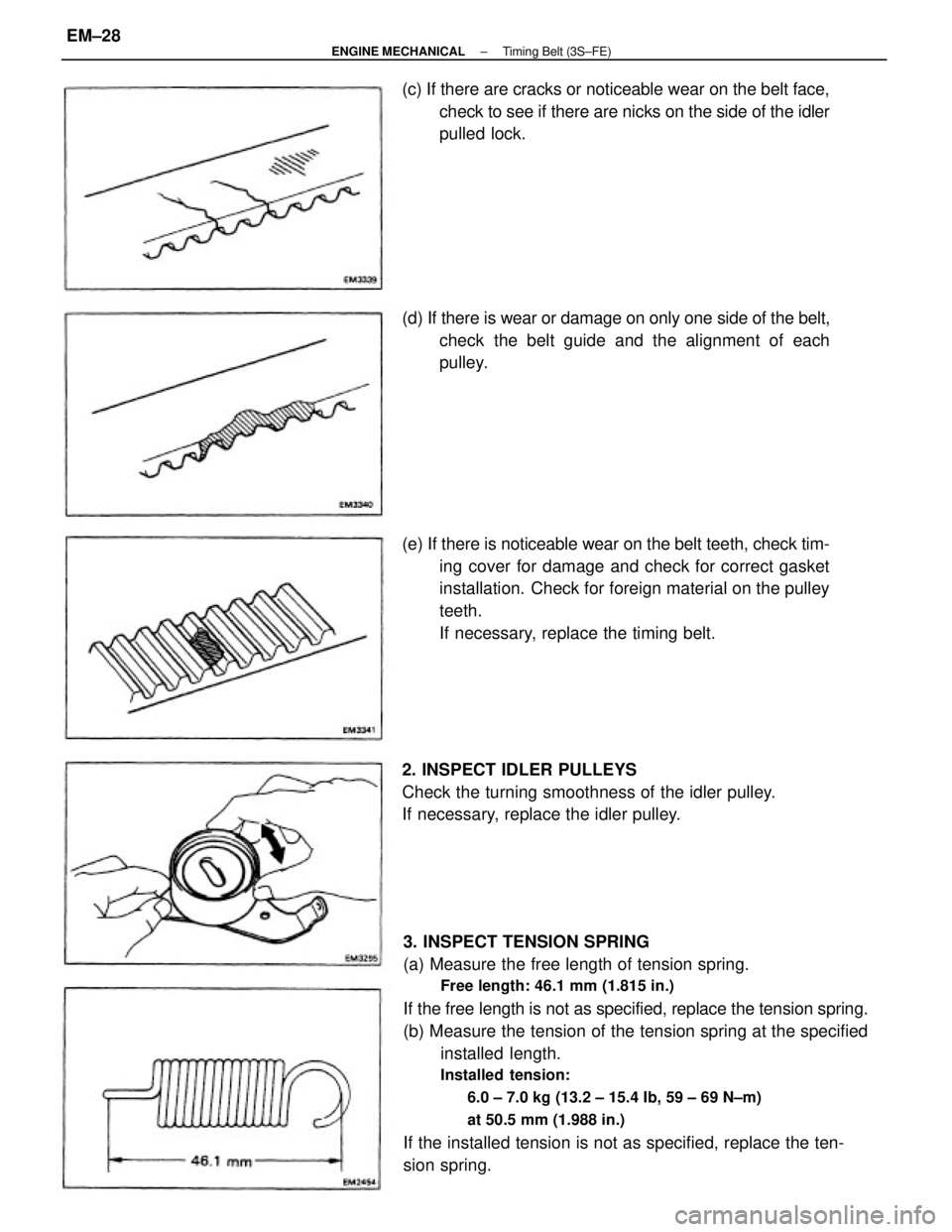
3. INSPECT TENSION SPRING
(a) Measure the free length of tension spring.
Free length: 46.1 mm (1.815 in.)
If the free length is not as specified, replace the tension spring.
(b) Measure the tension of the tension spring at the specified
installed length.
Installed tension:
6.0 ± 7.0 kg (13.2 ± 15.4 Ib, 59 ± 69 N±m)
at 50.5 mm (1.988 in.)
If the installed tension is not as specified, replace the ten-
sion spring. (e) If there is noticeable wear on the belt teeth, check tim-
ing cover for damage and check for correct gasket
installation. Check for foreign material on the pulley
teeth.
If necessary, replace the timing belt. (c) If there are cracks or noticeable wear on the belt face,
check to see if there are nicks on the side of the idler
pulled lock.
2. INSPECT IDLER PULLEYS
Check the turning smoothness of the idler pulley.
If necessary, replace the idler pulley. (d) If there is wear or damage on only one side of the belt,
check the belt guide and the alignment of each
pulley.
± ENGINE MECHANICALTiming Belt (3S±FE)EM±28