1973 DATSUN B110 low oil pressure
[x] Cancel search: low oil pressurePage 54 of 513

through
all
drive
positions
and
place
the
lever
in
park
P
position
In
this
inspection
the
car
must
be
placed
on
a
level
surface
The
amount
of
the
oil
varies
with
the
temperature
As
a
rule
the
oil
level
must
be
measured
after
its
tempera
ture
becomes
sufficiently
high
I
Fill
the
oil
to
the
line
H
The
difference
of
capacities
between
both
H
and
L
is
approximately
0
4
liter
7
8
U
S
pt
3
4
Imper
pt
and
therefore
take
care
not
to
fill
beyond
the
line
H
2
At
the
time
of
the
above
topping
up
and
changing
of
oil
care
should
be
taken
of
to
prevent
mixing
the
oil
with
dust
and
water
2
Inspecting
oil
condition
The
condition
of
oil
sticking
to
the
level
gauge
indicates
whether
to
over
haul
and
repair
the
transmission
or
look
for
the
defective
part
If
the
oil
has
deteriorated
into
a
varnish
like
quality
it
causes
the
con
trol
valve
to
stick
The
blackened
oil
gives
the
proof
of
the
burned
clutch
brake
band
etc
In
these
cases
the
transmission
must
be
replaced
Notes
a
In
oil
level
checking
use
special
paper
waste
to
handle
the
level
gauge
and
take
care
not
to
let
the
scraps
of
paper
and
cloth
tick
to
the
gauge
b
Insert
the
gauge
fully
and
take
it
out
quickly
before
splashing
oil
adheres
to
the
gauge
and
theu
observe
the
level
c
Use
automatic
transmission
fluid
having
DEXRON
iden
tIficatIon
only
in
the
3N71
B
automatic
transmission
d
Pay
atteutIon
because
the
oil
to
be
used
dIffers
from
that
i
used
in
the
Nissan
Full
Automatic
Transmission
3N7IA
Never
mix
the
oil
with
that
CHASSIS
Inspection
and
repair
of
oil
leakage
When
oil
leakage
takes
place
the
portion
near
the
leakage
is
covered
with
oil
presenting
difficulty
in
de
tecting
the
spot
Therefore
the
places
where
oil
seals
and
gaskets
are
equipped
are
enumerated
below
I
Converter
housing
The
rubber
ring
of
oil
pump
hous
ing
The
oil
eaI
of
oil
pump
housing
The
oil
seal
of
engine
crankshaft
The
bolts
of
converter
housing
to
case
2
Transmission
and
rear
extension
Junction
of
transmission
and
rear
extension
Oil
tube
connectors
Oil
pan
Oil
pressure
inspection
holes
Refer
to
Figure
AT
112
The
mounting
portion
of
vacuum
diaphragm
and
downshift
solenoid
Breather
and
oil
charging
pipe
Speedometer
pinion
sleeve
The
oil
seal
of
rear
extension
To
exactly
locate
the
place
of
oil
leakage
proceeds
as
follows
Place
the
vehicle
in
a
pit
and
by
sampling
the
leaked
oil
examine
whe
ther
it
is
the
torq
le
converter
oil
or
not
The
torque
converter
oil
assumes
color
like
red
wine
when
shipped
from
the
factory
so
it
is
ea
ily
distin
guished
from
engine
oil
or
gear
oil
Cleanly
wipe
off
the
leaking
oil
and
dust
and
detect
the
spot
of
oil
leakage
Use
nonflammable
organic
solvent
such
as
carbon
tetrachloride
for
wip
ing
Raise
the
oil
temperature
by
op
erating
the
engine
and
shift
the
lever
to
0
to
heighten
the
oil
pressure
The
spot
of
oil
leakage
will
then
be
found
more
easily
Note
A
the
oil
leakage
from
the
breather
does
not
take
place
except
when
running
at
high
speed
it
is
impossible
to
locate
the
spot
of
leakage
with
vehicle
stalled
AT
50
Checking
engine
idling
rprn
The
engine
idling
revolution
should
be
properly
adjusted
If
the
engine
revolution
is
too
low
the
engine
does
not
operate
smoothly
and
if
too
high
a
strong
shock
or
creep
develops
when
changing
over
from
N
to
D
or
R
Specified
idling
speed
650
rpm
at
D
position
800
rpm
at
N
position
Checking
and
adjusting
kick
down
switch
and
downshift
solenoid
When
the
kick
down
operation
is
not
made
properly
or
the
speed
chang
ing
point
is
too
high
check
the
kick
down
switch
downshift
solenoid
and
wiring
between
them
When
the
igni
tion
key
is
positioned
at
the
1st
stage
and
the
accelerator
pedal
is
depressed
deeply
the
switch
contact
should
be
closed
and
the
solenoid
should
click
If
it
does
not
click
it
indicates
a
defect
Then
check
each
part
with
the
testing
instruments
See
Figure
AT
I09
0
0
1
M
r
7
I
Y
ATl08
Fig
A
T
l
09
Downshift
solenoid
Note
Watch
for
oil
leakage
from
transmission
case
Page 57 of 513

Checking
speed
changing
condition
The
driver
s
feeling
during
gear
changes
should
also
be
checked
at
tentively
1
A
sharp
shock
or
unsmoothness
are
felt
during
a
gear
change
2
A
gear
change
is
made
with
a
long
and
dragging
feeling
These
indicate
that
the
throttle
pressure
is
too
low
or
some
valve
connected
to
the
throttle
is
defective
Checking
items
during
speed
change
1
In
D
range
gear
changes
DI
o
D2
D3
are
effected
In
R
range
the
speed
does
not
increase
2
The
kick
down
operates
properly
3
By
moving
the
lever
from
D
into
I
gear
changes
D3
2
12
II
are
effected
In
the
ranges
12
and
II
the
engine
braking
works
properly
4
In
the
speed
does
not
in
crease
5
Should
be
quickly
fixed
at
2
range
6
In
P
vehicle
can
be
parked
properly
If
any
malfunction
occurs
in
the
second
gear
during
the
road
test
that
is
if
vehicle
shakes
drags
or
sling
in
shifting
up
from
DI
directly
to
D3
or
in
shifting
up
from
D
to
W
I
r
I
1
1
I
2
31
I
I
I
I
I
t
Lh
I
I
I
I
1000
lsOo
2000
2500
Output
shaft
speed
rpm
AUTOMATIC
TRANSMISSION
D2
the
brake
band
should
be
ad
justed
If
these
troubles
remain
after
Shift
schedule
o
Full
throttlell
e
2100
E
E
200
is
Z
cu
300
mmHg
soo
o
soo
LINE
PRESSURE
TEST
When
any
slipping
occurs
in
clutch
or
brake
or
the
feeling
during
a
speed
change
is
not
correct
the
line
pressure
must
be
checked
Measuring
the
line
pressure
is
done
by
a
pressu
re
gauge
attached
to
two
pressure
measuring
holes
after
re
moving
blind
plugs
located
at
trans
mission
case
See
Figure
AT
112
The
line
pressure
measurement
is
begun
at
idling
and
taken
step
by
step
by
enlarging
the
throttle
opening
1
A
sharp
shock
in
up
shifting
or
too
high
changing
speeds
are
caused
mostly
by
too
high
throttle
pressure
2
Slipping
or
incapability
of
opera
Line
pressure
governor
feed
pressure
At
cut
back
point
After
cut
back
Throttle
opening
under
approximately
over
approximately
15
kmfh
9
MPH
35
kmfh
22
MPH
Unit
mmHg
Unit
kg
cm2
psi
Unit
kg
cm2
psi
Full
throttle
0
94
to
11
0
134
to
156
5
5
to
6
5
78
to
92
Minimum
throttle
450
3
0
to
4
0
43
to
57
3
0
to
4
0
43
to
57
Full
throttle
0
10
0
to
12
0
142
to
171
5
5
to
7
0
78
to
100
Minimum
throttle
450
6
0
to
12
0
85toI71
5
5
to
7
0
78
to
100
Full
throttle
0
14
0
to
16
0
199
to
228
14
0
to
16
0
199
to
228
Minimum
throttle
450
3
0
to
5
5
4310
78
3
0
to
5
5
43
to
78
Range
D
2
R
the
brake
band
is
adjusted
check
the
servo
piston
seal
for
oil
leakage
3
30ixI
3500
000
AT110
Fig
A
T
llI
Shift
schedule
tion
is
mostly
due
to
oil
pressure
leakage
within
the
gear
trains
or
spool
valve
AT113
I
Line
pressure
2
Governor
reed
3
Servo
release
pressure
Fig
A
T
112
MeCJ8uring
line
pressure
Notes
a
The
line
pressure
during
idling
corresponds
to
the
oil
pressure
before
cut
down
at
minimum
throttle
b
The
oil
pressure
After
cut
back
means
that
after
the
pressure
modifier
valve
has
operated
AT
53
Page 58 of 513
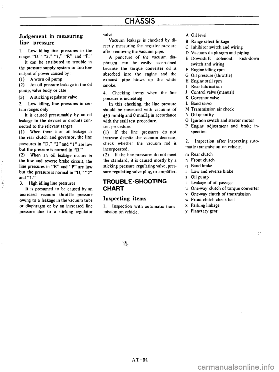
Judgement
in
measurmg
line
pressure
I
Low
idling
line
pressures
in
the
ranges
D
2
loR
and
P
It
can
be
artributed
to
trouble
in
the
pressure
supply
system
or
too
low
output
of
power
caused
by
1
A
worn
oil
pump
2
An
oil
pressure
leakage
in
the
oil
pump
valve
body
or
case
3
A
sticking
regulator
valve
2
Low
idling
line
pressures
in
cer
tain
ranges
only
It
is
caused
pressumabIy
by
an
oil
leakage
in
the
devices
or
circuits
con
nected
to
the
relevant
ranges
1
When
there
is
an
oil
leakage
in
the
rear
clutch
and
governor
the
line
pressures
in
D
2
and
I
are
low
but
the
pressure
is
normal
in
R
2
When
an
oil
leakage
occurs
in
the
low
and
reverse
brake
circuit
the
line
pressures
in
R
and
p
are
low
but
the
pressure
is
normal
in
0
2
and
I
3
High
idling
line
pressures
It
is
presumed
to
be
caused
by
an
increased
vacuum
throttle
pressure
owing
to
a
leakage
in
the
vacuum
tube
or
diaphragm
or
by
an
increased
line
pressure
due
to
a
sticking
regulator
CHASSIS
valve
Vacuum
leakage
is
checked
by
di
reetly
measuring
the
negative
pressure
after
removing
the
vacuum
pipe
A
puncture
of
the
vacuum
dia
phragm
can
be
easily
ascertained
because
the
torque
converter
oil
is
absorbed
into
the
engine
and
the
exhaust
pipe
blows
up
the
white
smoke
4
Checking
items
when
the
line
pressure
is
increasing
In
trJs
checking
the
line
pressure
should
be
measured
with
vacuums
of
450
mmHg
and
0
mmHg
in
accordance
with
the
stall
test
procedure
test
procedure
1
If
the
line
pressures
do
not
increase
despite
the
vacuum
decrease
check
whether
the
vacuum
rod
is
incorporated
2
If
the
line
pressures
do
not
meet
the
standard
it
is
caused
mostly
by
a
sticking
pressure
regulating
valve
pres
sure
regulating
valve
plug
or
amptifier
TROUBLE
SHOOTING
CHART
Inspecting
items
1
Inspection
with
automatic
trans
mission
on
vehicle
J
AT
54
A
Oil
level
B
Range
selecr
linkage
C
Inhibitor
switch
and
wiring
D
Vacuum
diaphragm
and
piping
E
Downshift
solenoid
kick
down
switch
and
wiring
F
Engine
idling
rpm
G
Oil
pressure
throttle
H
Engine
stall
rpm
I
Rear
lubrication
J
Control
valve
manual
K
Governor
valve
L
Band
servo
M
Transmission
air
check
N
Oil
quantity
o
Ignition
switch
and
starter
motor
P
Engine
adjustment
and
brake
in
spection
2
Inspection
after
inspecting
auto
matic
transmission
on
vehicle
m
Rear
clutch
n
Front
clutch
q
Band
brake
r
Low
and
reverse
brake
s
Oil
pump
Leakage
of
oil
passage
u
One
way
clutch
of
torque
converter
v
One
way
clutch
of
transmission
w
Front
clutch
check
ball
x
Parking
linkage
y
Planetary
gear
Page 62 of 513
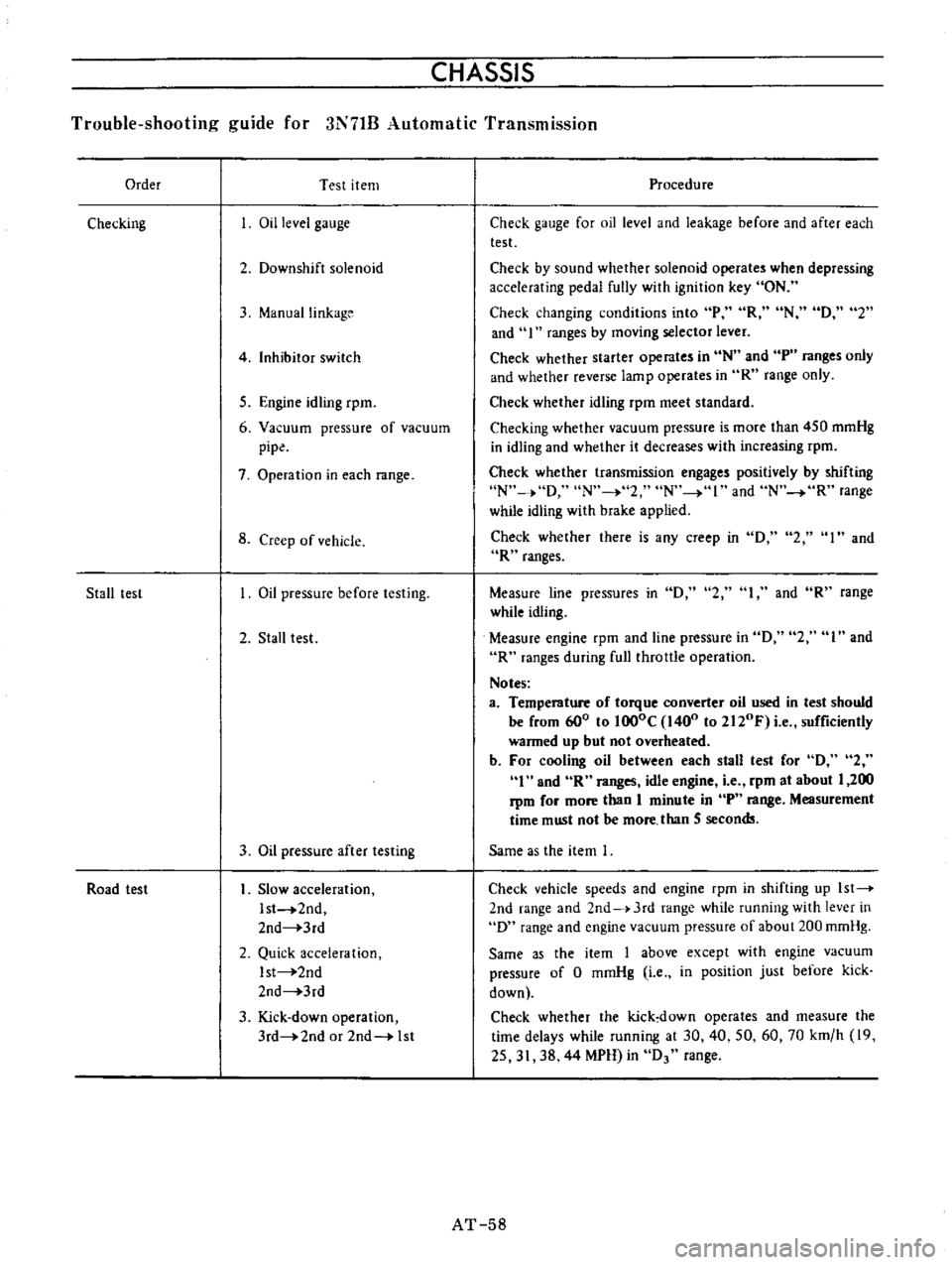
CHASSIS
Trouble
shooting
guide
for
3N71B
Automatic
Transmission
Order
Test
item
Checking
Oil
level
gauge
2
Downshift
solenoid
3
ManuaIlinkage
4
Inhibitor
switch
5
Engine
idling
rpm
6
Vacuum
pressure
of
vacuum
pipe
7
Operation
in
each
range
8
Creep
of
vehicle
Stall
lest
Oil
pressure
before
testing
2
Stall
test
3
Oil
pressure
after
testing
Road
test
Slow
acceleration
Ist
2nd
2nd
3rd
2
Quick
acceleration
Ist
2nd
2nd
3rd
3
Kick
down
operation
3rd
2nd
or
2nd
1st
Procedure
Check
gauge
for
oil
level
and
leakage
before
and
after
each
test
Check
by
sound
whether
solenoid
operates
when
depressing
accelerating
pedal
fully
with
ignition
key
ON
Check
changing
conditions
into
P
R
N
D
2
and
I
ranges
by
moving
selector
lever
Check
whether
starter
operates
in
N
and
tp
ranges
only
and
whether
reverse
lamp
operates
in
R
range
only
Check
whether
idling
rpm
meet
standard
Checking
whether
vacuum
pressure
is
more
than
450
mmHg
in
idling
and
whether
it
decreases
with
increasing
rpm
Check
whether
transmission
engages
positively
by
shifting
N
o
D
N
2
N
I
and
N
R
range
while
idling
with
brake
applied
Check
whether
there
is
any
creep
in
D
2
I
and
R
ranges
2
1
and
R
range
Measure
line
pressures
in
D
while
idling
Measure
engine
rpm
and
line
pressure
in
D
2
I
and
R
ranges
during
fullthrallIe
operation
Notes
a
Temperature
of
torque
converter
oil
used
in
test
should
be
from
600
to
lOOoC
1400
to
2120F
i
e
sufficiently
warmed
up
but
not
overheated
b
For
cooling
oil
between
each
stall
test
for
D
2
1
and
R
ranges
idle
engine
i
e
rpm
at
about
1
200
rpm
for
more
than
1
minute
in
P
range
Measurement
time
must
not
be
more
than
5
secon
Same
as
the
item
I
Check
vehicle
speeds
and
engine
rpm
in
shifting
up
1st
2nd
range
and
2nd
J
3rd
range
while
running
with
lever
in
D
range
and
engine
vacuum
pressure
of
about
200
mmHg
Same
as
the
item
1
above
except
with
engine
vacuum
pressure
of
0
mmHg
i
e
in
position
just
before
kick
down
Check
whether
the
kick
down
operates
and
measure
the
time
delays
while
running
at
30
40
50
60
70
km
h
19
25
31
38
44
MPH
in
D
range
AT
58
Page 64 of 513

CHASSIS
SERVICE
DATA
AND
SPECIFICATIONS
General
specifications
Torque
converter
Type
Stall
torque
ratio
Transmission
Type
Control
elements
Gear
ratio
Selector
positions
Oil
pump
Type
Number
of
pump
Oil
Capacity
Hydraulic
control
system
Lubrication
system
Cooling
system
Multiple
disc
clutch
Band
brake
Multiple
disc
brake
One
way
clutch
1st
lnd
3rd
Reverse
P
Park
R
Reverse
N
Neutral
D
Drive
1
lnd
lock
I
Lock
up
AT
60
Symmetrical3
element
I
stage
l
phase
torque
converter
coupling
2
0
I
3
speed
forward
and
one
speed
reverse
with
planetary
gear
train
1
I
I
I
2
458
1
458
1
000
2
182
The
transmission
is
placed
in
neutral
The
output
shaft
is
fixed
The
engine
can
be
started
Backward
running
The
transmission
is
in
neutral
The
engine
can
be
started
Up
or
downshifts
automatically
to
and
from
1st
lnd
and
top
Fixed
at
2nd
Fixed
at
low
or
downshifts
from
2nd
Internally
intermeslting
involute
gear
pump
Automatic
transmission
fluid
Dexron
type
5
5
liters
57
8
U
S
qts
47
8
Imp
qts
Approximately
1
7
liters
27
8
U
S
qts
2
3
8
Imp
qts
in
torque
converter
Controlled
by
detecting
the
negative
pressure
of
intake
manifold
and
the
revolution
speed
of
output
shaft
Forced
lubrication
by
an
oil
pwnp
Air
cooled
Page 66 of 513
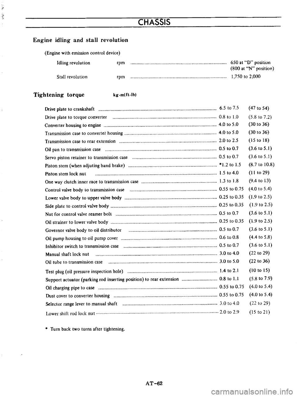
CHASSIS
Engine
idling
and
stall
revolution
Engine
with
emission
control
device
Idling
revolution
rpm
650
at
0
position
800
at
N
position
1
750
to
2
000
Stall
revolution
rpm
Tightening
torque
kg
m
ft
Ib
Test
plug
oil
pressure
inspection
hole
Support
actuator
parking
rod
inserting
position
to
rear
extension
Oil
charging
pipe
to
case
Dust
cover
to
converter
housing
Selector
range
lever
to
manual
shaft
Lower
shift
rod
lock
nut
6
5
t07
5
47
to
54
0
8
to
1
0
5
8
to
7
2
4
0
to
5
0
30
to
36
4
0
to
5
0
30
to
36
2
0
to
2
5
15
to
18
0
5
to
0
7
3
6
to
5
1
0
5
to
0
7
3
6toS
I
1
2
to
1
5
8
7
to
10
8
1
5
to
4
0
II
to
29
1
3
to
1
8
9
4
to
13
0
55
to
0
75
4
0
to
5
4
0
25
to
0
35
1
9
to
2
5
0
25
to
0
35
1
9
to
2
5
0
5
to
0
7
3
6
to
5
I
0
25
to
0
35
1
9
to
2
5
0
5
to
0
7
3
6
to
5
1
0
6
to
0
8
4
4
to
5
8
0
5
to
0
7
3
6
to
5
1
3
0
to
4
0
22
to
29
3
0
to
5
0
22
to
36
14
to
2
1
10
to
15
0
8
to
l
l
5
8
to
7
9
0
55
to
0
75
4
0
to
5
4
0
55
to
0
75
4
0
to
5
4
3
0
to
4
0
22
to
29
2
0
to
2
9
15
to
21
Drive
plate
to
crankshaft
Drive
plate
to
torque
converter
Converter
housing
to
engine
Transmission
case
to
converter
housing
Transmission
case
to
rear
extension
Oil
pan
to
transmission
case
Servo
piston
retainer
to
transmission
case
Piston
stem
when
adjuting
band
brake
Piston
stem
lock
nut
One
way
clutch
inner
race
to
transmission
case
Control
valve
body
to
transmission
case
Lower
valve
body
to
upper
valve
body
Side
plate
to
control
valve
body
Nut
for
control
valve
reamer
bolt
Oil
strainer
to
lower
valve
body
Governor
valve
body
to
oil
distributor
Oil
pump
housing
to
oil
pump
cover
Inhibitor
switch
to
transmh
sion
case
Manual
shaft
lock
nut
Oil
tube
to
transmission
case
Turn
back
two
turns
after
tightening
AT
62
Page 95 of 513
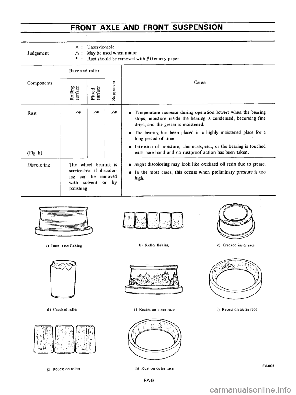
Judgement
Components
Rust
Fig
h
Discoloring
FRONT
AXLE
AND
FRONT
SUSPENSION
x
f
Unserviceable
May
be
used
when
minor
Rust
should
be
removed
with
0
emery
paper
Race
and
roller
00
u
o
o
Ou
u
The
wheel
bearing
is
serviceable
if
discolor
ing
can
be
removed
with
solvent
or
by
polishing
r
c
1
1
Ie
r
r
iJ
a
Inner
race
flaking
d
Cracked
roller
J
I
11
Ji
l
L
i
I
11
J
g
Recess
on
roller
o
0
0
CIl
Cause
Temperature
increase
during
operation
lowers
when
the
bearing
stops
moisture
inside
the
bearing
is
condensed
becoming
fine
drips
and
the
grease
is
moistened
The
bearing
has
been
placed
in
a
highly
moistened
place
for
a
long
period
of
time
Intrusion
of
moisture
chemicals
etc
or
the
bearing
is
touched
with
bare
hand
and
no
rustproof
action
has
been
taken
Slight
discoloring
may
look
like
oxidized
oil
stain
due
to
grease
In
the
most
cases
this
occurs
when
preliminary
pressure
is
too
high
b
Roller
flaking
c
Cracked
inner
race
I
lJ
f
t
j
e
Recess
on
inner
race
f
Recess
on
outer
race
cc
h
Rust
on
outer
race
FADD7
FA
9
Page 102 of 513
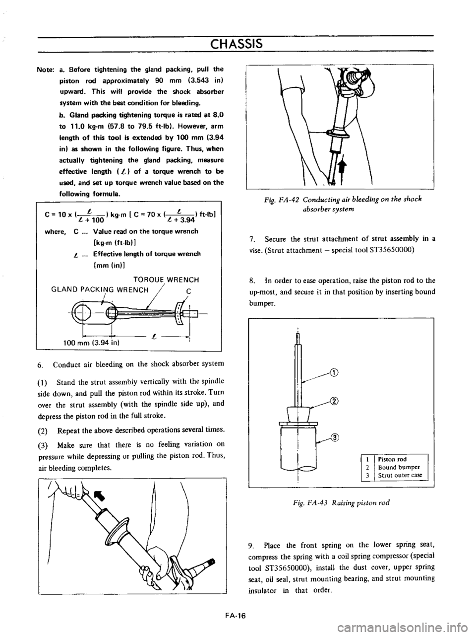
CHASSIS
Note
a
Before
tightening
the
gland
packing
pull
the
piston
rod
approximately
90
mm
3
543
in
upward
This
will
provide
the
shock
absorber
system
with
the
best
condition
for
bleeding
b
Gland
packing
tightening
torque
is
rated
at
8
0
to
11
0
kg
m
57
8
to
79
5
ft
Ib
However
arm
length
of
this
tool
is
extended
by
100
mm
3
94
in
as
shown
in
the
following
figure
Thus
when
actually
tightening
the
gland
packing
measure
effective
length
L
of
a
torque
wrench
to
be
used
and
set
up
torque
wrench
value
based
on
the
following
formula
C
10
x
l
I
kg
m
C
70
x
l
I
ft
lbJ
100
l
3
94
where
C
Value
read
on
the
torque
wrench
kg
m
ft
lbIJ
Effective
length
of
torque
wrench
mm
in
l
TOROUE
WRENCH
GLAND
PACKING
WRENCH
I
C
4
F
r
I
L
I
100
mm
3
94
in
6
Conduct
air
bleeding
on
the
shock
absorber
system
1
Stand
the
strut
assembly
vertically
with
the
spindle
side
down
and
pull
the
piston
rod
within
its
stroke
Turn
over
the
strut
assembly
with
the
spindle
side
up
and
depress
the
piston
rod
in
the
full
stroke
2
Repeat
the
above
described
operations
several
times
3
Make
sure
that
there
is
no
feeling
variation
on
pressure
while
depressing
or
pulling
the
piston
rod
Thus
air
bleeding
completes
J
FA
16
Fig
FA
42
ConductingaiT
bleeding
on
the
shock
absorber
system
7
Secure
the
strut
attachment
of
strut
assembly
in
a
vise
Strut
attachment
special
tool
Sn5650000
8
In
order
to
ease
operation
raise
the
piston
rod
to
the
up
most
and
secure
it
in
that
position
by
inserting
bound
bum
per
t
D
I
T
I
c
I
Piston
rod
2
Bound
bumper
3
Strut
outer
case
Fig
FA
43
Raising
piston
rod
9
Place
the
front
spring
on
the
lower
spring
seat
compress
the
spring
with
a
coil
spring
compressor
special
tool
Sn5650000
install
the
dust
cover
upper
spring
seat
oil
seal
strut
mounting
bearing
and
strut
mounting
insulator
in
that
order