1973 DATSUN B110 low oil pressure
[x] Cancel search: low oil pressurePage 29 of 513
AUTOMATIC
TRANSMISSION
D
range
Top
gear
Low
r
Fl
B
e
B
e
B
14
TIC
Uil
Pr
1
v
Fl
Lubfk
tlon
O
ein
14
I
Velv8
l
Front
Lub
icet
Orlfiu
Check
V
I
8
6
13
@
2nd
3rd
Shifl
Velv
13
I
O
inV
Throttle
O
in
Ve
l
1
22
21
3
lit
2nd
Shift
Ve
5
M
V
I
5
n
NOle
M
ked
O
ein
Linep
s
Go
no
f
d
P
G
ernorp
Torqu
con
tt
p
secondary
G
norv
Ime
v
Governor
v
Th
Olt
p
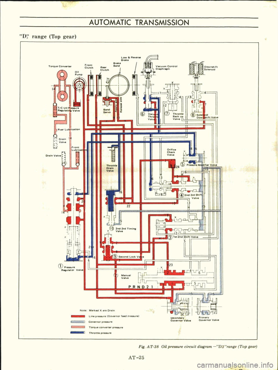
Fig
A
T
38
Oil
pressure
circuit
diagram
D3
range
Top
gear
AT
25
Page 33 of 513
AUTOMATIC
TRANSMISSION
2
range
2nd
gear
To
queCo
Low
a
R
8
ka
8
ke
Oownltlift
Solenoid
14
12
@
VK
Throt
V
I
7
Throttl
Sack
up
V
lv
@SOl
o
if
V
I
Front
Lubrk
n
Orltlc
Ch
k
V
l
Dr
n
V
1
ThroW
Drain
V
Ye
Pt
Mod
fier
V
I
IS
8Rt
@2
3rdTimi
Sl
It
V
12
3
ht
2nd
Sf
ll
5
Secor
d
Lock
V
I
3
I
@
M
nu
l
V
I
5
I1Jl
ill
Pr
ur
R
vulatO
V
I
Note
M
keel
r
D
in
a
P
imary
Go
no
V
h
Line
pr
IGo
no
teed
p
luure
Go
no
p
E2I
B
Ii
iiiIJ
To
c
U
con
t
p
Th
oUl
prn
SecOnda
y
00
0
V
lv
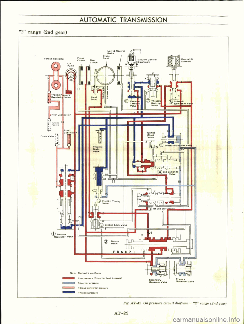
Fig
AT
42
Oil
pressure
circuit
diagram
2
range
2nd
gear
AT
29
Page 34 of 513
CHASSIS
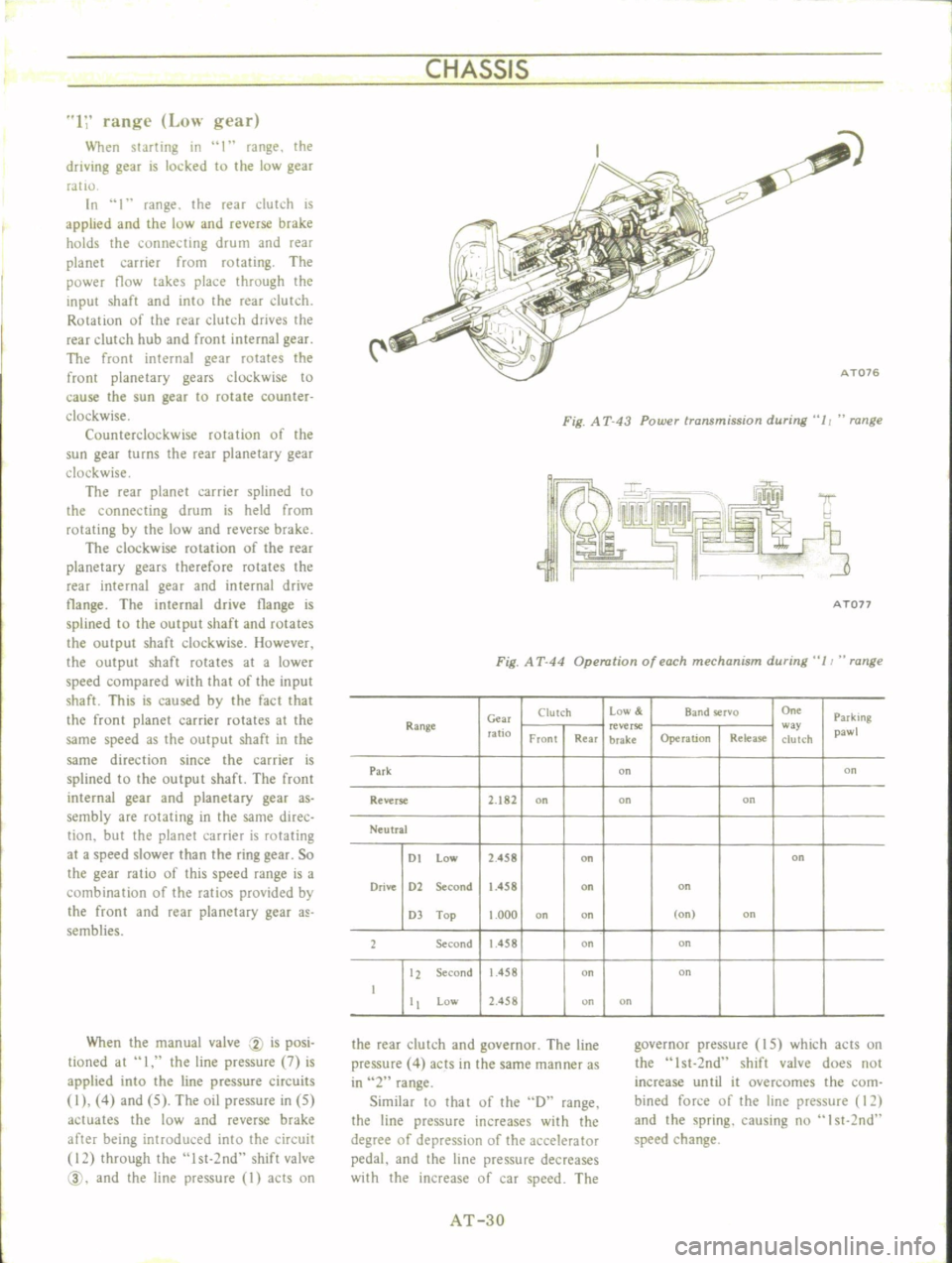
1
range
Low
gear
When
starting
in
I
range
the
driving
gear
is
locked
to
the
low
gear
ratIO
In
1
range
the
reaT
dutch
is
applied
and
the
low
and
reverse
brake
holds
the
connecting
drum
and
rear
planet
carrier
from
rotating
The
power
flow
takes
place
through
the
input
shaft
and
into
the
rear
dutch
Rotation
of
the
rear
clutch
drives
the
rear
clutch
hub
and
front
internal
gear
The
front
internal
gear
rotates
the
front
planetary
gears
clockwise
to
cause
the
sun
gear
to
rotate
counter
clockwise
Counterclockwise
rotation
of
the
sun
gear
turns
the
rear
planetary
gear
clockwise
The
rear
planet
carrier
splined
to
the
connecting
drum
is
held
from
rotating
by
the
low
and
reverse
brake
The
clockwise
rotation
of
the
rear
planetary
gears
therefore
rotates
the
rear
internal
gear
and
internal
drive
tlange
The
internal
drive
tlange
is
splined
to
the
output
shaft
and
rotates
the
output
shaft
clockwise
However
the
output
shaft
rotates
at
a
lower
speed
compared
with
that
of
the
input
shaft
This
is
caused
by
the
fact
that
the
front
planet
carrier
rotates
at
the
same
speed
as
the
output
shaft
in
the
same
direction
since
the
carrier
is
splined
to
the
output
shaft
The
front
internal
gear
and
planetary
gear
as
sembly
are
rotating
in
the
same
direc
tion
but
the
planet
carrier
is
rotating
at
a
speed
slower
than
the
ring
gear
So
the
gear
ratio
of
this
speed
range
is
a
combination
of
the
ratios
provided
by
the
front
and
rear
planetary
gear
a
semblies
When
the
manual
valve
CV
is
posi
tioned
at
I
the
line
pressure
7
is
applied
into
the
line
pressure
circuits
I
4
and
5
The
oil
pressure
in
5
actuates
the
low
and
reverse
brake
after
being
introduced
into
the
circuit
12
through
the
lst
2nd
shift
valve
@
and
the
line
pressure
I
acts
on
i
C
AT076
Fig
A
T
43
Power
transmission
during
11
range
A
Ton
Fig
A
T
44
Operation
of
each
mechanism
during
11
range
Clutch
Low
Band
rvo
On
Parking
Range
Gm
ratio
reverse
w
pawl
Front
Rear
brake
Operation
Release
clutch
Park
on
on
Reverse
2
182
on
on
on
Neutral
DI
low
2
458
on
on
Drive
D2
Second
1
458
on
on
D
Top
1
000
on
on
on
on
2
Second
1
458
on
on
12
Second
1
458
on
on
I
Low
2
458
on
on
the
rear
clutch
and
governor
The
line
pressure
4
acts
in
the
same
manner
as
in
2
range
Similar
10
that
of
the
D
range
the
line
pressure
increases
with
the
degree
of
depressiun
of
the
accelerator
pedal
and
the
line
pressure
decreases
with
the
increase
of
car
speed
The
governor
pressure
IS
which
acts
on
the
Ist
2nd
shift
valve
does
not
increase
until
it
overcomes
the
com
bined
force
of
the
line
pressure
12
and
the
spring
causing
nu
I
st
2nd
speed
change
AT
3D
Page 35 of 513
AUTOMATIC
TRANSMISSION
1
range
Low
gear
Lo
Rev
B
k
Brat
Oownthift
SolenoOCl
14
T
COUP
A
uu
e
IV
hl
I
R
L
ub
c
tlon
Dr
n
It
Val
9
10
v
nHOI
V
l
in
jl
8
Sale
d
QI
Cow
ilt
V
D
nV
Front
Lubtlc
t
Oritice
ChotCk
Valv
I
I
14
Throttle
Dr
V
lv8
I
Pre
Modil
lv8
15
3
151
2nd
j
Pre
u
Re1julato
Valva
@
n
No
Marked
er
0
8in
Primary
Gove
nor
V
I
Line
p
Go
erno
feed
p
euu
GOvernor
preuu
lEII
IIIII
To
que
con
8
t8
pres
He
Th
ottl
p
Second
Go
l
Io
vel
8
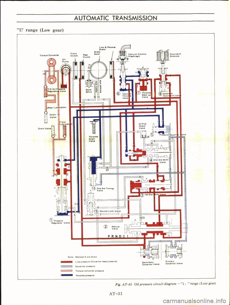
Fig
A
T
45
Oil
pressure
circuit
diagram
11
range
Low
gear
AT
31
Page 47 of 513

3
Blowout
piston
by
directing
a
jet
of
air
into
hole
in
clutch
drum
See
Figure
AT
S
7
AT155
Fig
AT
87
Blowing
out
piston
Inspection
Refer
to
covering
topic
under
Front
Clutch
Assembly
Assembly
is
reverse
order
of
disas
sembly
Dip
all
parts
in
clean
auto
malic
transmission
fluid
before
as
sembling
Note
that
the
number
of
drive
and
driven
plates
varies
with
types
of
vehicles
For
details
refer
to
Service
Data
Specifications
I
After
rear
clutch
is
assembled
check
to
be
sure
that
clearance
be
tween
snap
ring
CD
and
retaining
plate
CV
is
held
within
prescribed
tolerances
See
Figure
A
T
S8
Specified
clearance
1
0
to
1
5
mm
0
039
to
0
059
in
AT1S6
Fig
A
T
88
Measuring
ring
to
plate
clearance
2
Testing
rear
clutch
Install
rear
clutch
on
oil
pump
cover
Blow
air
under
pressure
into
oil
hole
to
listen
for
definite
clutch
opera
tion
as
shown
in
Figure
AT
S9
AUTOMATIC
TRANSMISSION
AT157
Fig
AT
89
Testing
rear
clutch
Low
reverse
brake
Disassembly
I
Follow
steps
as
per
instructed
on
page
AT
38
2
Blowout
piston
by
directing
a
jet
of
air
into
oil
hole
in
clutch
piston
Inspection
I
Check
drive
plate
facing
for
wear
or
damage
if
necessary
replace
Refer
to
Service
Data
Specifications
for
limits
2
Test
if
piston
return
spring
is
not
weakened
Discard
if
weakened
too
badly
beyond
use
3
Replace
any
defective
parts
with
new
ones
Assembly
1
After
low
reverse
piston
is
installed
assemble
thrust
spring
ring
return
spring
thrust
washer
and
one
way
clutch
inner
race
With
the
aid
of
Hex
head
Extension
ST25570000
tighten
hex
head
slotted
bolt
1
3
to
1
8
kg
m
9
4
to
13
ft
Ib
2
Enter
dished
plate
driven
plate
drive
plate
and
retaining
plate
into
transmission
case
in
this
written
order
Install
snap
ring
to
secure
the
instal
lation
Note
The
number
of
drive
and
driven
plates
varies
with
types
of
vehi
cles
For
detailed
information
refer
to
Service
Data
Specifi
cations
AT
43
3
Without
disturbing
the
above
setting
check
to
be
sure
that
clearance
between
snap
ring
and
retaining
plate
is
held
within
specified
limits
If
nec
essary
try
with
other
plates
having
different
thickness
until
correct
clear
ance
is
obtained
Specified
clearance
O
SO
to
1
05
mm
0
031
to
0
041
in
4
Blow
under
pressure
air
into
oil
hole
in
low
reverse
brake
to
listen
for
definite
brake
operation
as
shown
in
Figure
AT
90
0j
L
J
1
1
I
1
I
Y
1
If
lY
v
A
we
1
a
II
I
7
r
AT158
Fig
AT
90
Testing
low
reverse
brake
Servo
piston
Disassembly
1
Blowout
piston
by
directing
a
jet
of
air
into
hole
in
release
side
of
piston
2
Remove
servo
piston
return
spring
Inspection
Check
piston
for
wear
damage
or
any
other
defects
which
might
inter
fere
with
proper
brake
operation
AT159
Fig
A
T
91
Removing
piston
Page 48 of 513
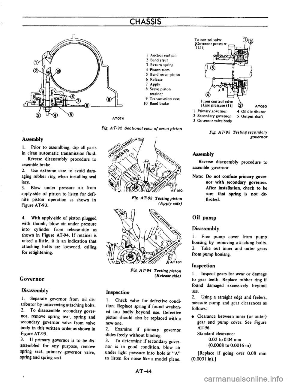
Assembly
I
Prior
10
assemlbing
dip
all
parts
in
clean
automatic
transmission
fluid
Reverse
disassembly
procedure
to
assemble
brake
2
Use
extreme
care
to
avoid
dam
aging
rubber
ring
when
installing
seal
lace
3
Blow
under
pressure
air
from
apply
side
of
piston
to
lislen
for
defi
nite
piston
operation
as
shown
in
Figure
AT
93
4
With
appIy
side
of
piston
plugged
with
thumb
blow
air
under
pressure
into
cylinder
from
release
side
as
shown
in
Figure
AT
94
If
retainer
is
raised
a
little
it
is
an
indication
that
attaching
bolts
are
loosened
calling
for
retightening
Governor
Disassembly
l
Separate
governor
from
oil
dis
tributor
by
unscrewing
attaching
bolts
2
To
disassemble
secondary
gover
nor
remove
spring
seat
spring
and
secondary
governor
valve
from
valve
body
in
this
written
order
as
shown
in
Figure
AT
95
3
If
primary
governor
is
to
be
dis
assembled
for
any
purpose
remove
spring
seat
primary
governor
valve
spring
and
spring
eal
CHASSIS
I
Anchor
end
pin
2
Band
strut
3
Return
spring
4
Piston
stem
5
Band
servo
piston
6
Release
7
Apply
8
Servo
piston
relainer
9
Transmission
case
10
Band
brake
AT074
Fig
A
T
92
Sectional
view
of
servo
piston
Fig
A
T
93
Testing
piston
Apply
side
Fig
A
T
94
Testing
pi8ton
Rele
side
Inspection
I
Check
valve
for
defective
condi
tion
Replace
spring
if
found
weaken
ed
too
badly
beyond
use
Defective
piston
should
also
be
replaced
with
a
new
one
2
Examine
if
primary
governor
slides
freely
without
binding
3
To
determine
if
secondary
gover
nor
is
in
good
condition
blow
air
under
light
pressure
into
hole
at
A
to
listen
for
noise
like
a
model
plane
AT
44
r
To
control
valve
Governor
pressure
15
1
4
From
control
valve
Line
pressure
I
I
Primary
governor
2
Secondary
governor
3
Governor
valve
body
A
TogO
4
Oil
distributor
5
Output
shaft
Fig
A
T
95
Testing
secondary
governor
Assembly
Reverse
disassembly
procedure
to
assemble
governor
Note
Do
nol
confuse
primary
gover
nor
wilh
secondary
governor
After
instaDation
check
to
be
sure
that
spring
is
nol
de
flecled
Oil
pump
Disassembly
I
Free
pump
cover
from
pump
housing
by
removing
attaching
bolts
2
Take
out
inner
and
outer
gears
from
pump
houisng
Inspection
1
Inspect
gears
for
wear
or
damage
to
gear
leeth
Replace
rubber
ring
if
found
damaged
excessively
beyond
use
2
Using
a
straight
edge
and
feelers
measure
pump
and
gear
clearances
as
follows
Clearance
between
inner
or
outer
gear
and
pump
cover
See
Figure
AT
96
Standard
clearance
0
02
to
0
04
mm
0
0008
to
0
0016
in
Replace
if
going
over
0
08
mm
0
0031
in
Page 51 of 513
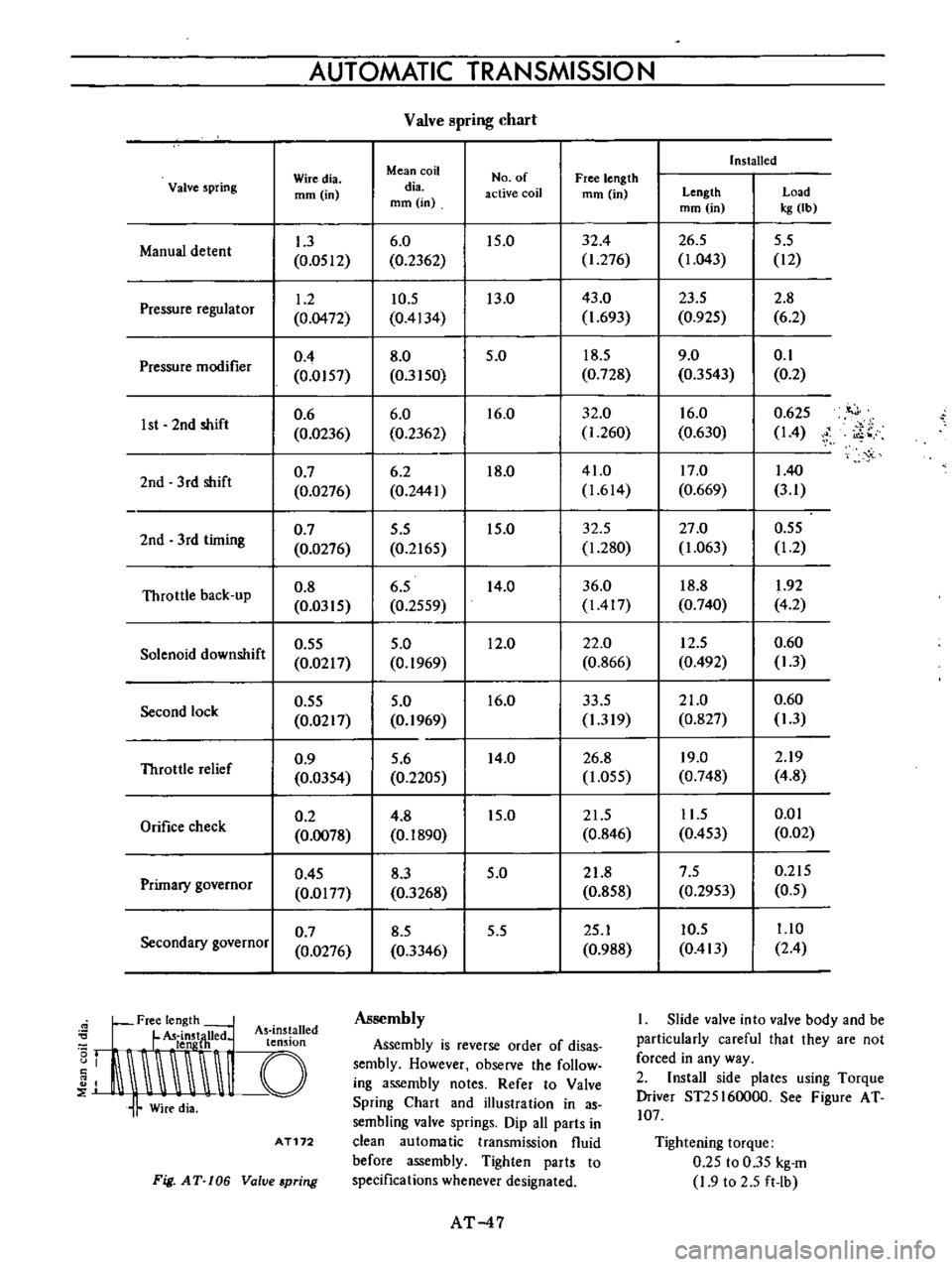
AUTOMATIC
TRANSMISSIO
N
Valve
pring
chart
Installed
Wiredia
Mean
coil
No
of
Free
length
Valve
spring
mm
in
dia
active
coil
mm
in
Length
Load
mm
in
mm
in
kg
Ib
1
3
6
0
15
0
32
4
26
5
5
5
Manual
detent
0
0512
0
2362
1
276
1
043
12
1
2
10
5
13
0
43
0
23
5
2
8
Pressure
regulator
0
0472
0
4134
1
693
0
925
6
2
0
4
8
0
5
0
18
5
9
0
0
1
Pressure
modifier
0
0157
0
3150
0
728
0
3543
0
2
0
6
6
0
16
0
32
0
16
0
0
625
it
J
1st
2nd
shift
0
0236
0
2362
1
260
0
630
14
i
o
0
7
6
2
18
0
41
0
17
0
140
2nd
3
rd
shift
0
0276
0
2441
1
614
0
669
3
1
0
7
5
5
15
0
32
5
27
0
0
55
2nd
3rd
timing
0
0276
0
2165
1
280
1
063
1
2
Throttle
back
up
0
8
6
5
14
0
36
0
18
8
1
92
0
0315
0
2559
1417
0
740
4
2
0
55
5
0
12
0
22
0
12
5
0
60
Solenoid
downshift
0
0217
0
1969
0
866
0
492
1
3
0
55
5
0
16
0
33
5
21
0
0
60
Second
lock
0
0217
0
1969
1
319
0
827
1
3
0
9
5
6
14
0
26
8
19
0
2
19
Throttle
relief
0
0354
0
2205
1
055
0
748
4
8
0
2
4
8
15
0
21
5
11
5
0
01
Orifice
check
0
0078
0
1890
0
846
0
453
0
02
0
45
8
3
5
0
21
8
7
5
0
215
Primary
governor
0
0177
0
3268
0
858
0
2953
0
5
0
7
8
5
5
5
25
1
10
5
1
10
Secondary
governor
0
0276
0
3346
0
988
0
413
2
4
Free
length
L
U
d
As
ins
alled
I
t
LldnstjH
e
t
n
Ion
J
I
I
Assembly
Assembly
is
reverse
order
of
disas
sembly
However
observe
the
follow
ing
assembly
notes
Refer
to
Valve
Spring
Chart
and
illustration
in
as
sembling
valve
springs
Dip
all
parts
in
clean
automatic
transmission
fluid
before
assembly
Tighten
parts
to
specifications
whenever
designated
AT172
Fig
AT
106
Value
pring
AT
47
I
Slide
valve
into
valve
body
and
be
particularly
careful
that
they
are
not
forced
in
any
way
2
Install
side
plates
using
Torque
Driver
ST25I60000
See
Figure
AT
107
Tightening
torque
0
25
to
0
35
kg
m
1
9
to
2
5
ft
Ib
Page 53 of 513

AUTOMATIC
TRANSMISSIO
N
TROUBLE
DIAGNOSES
AND
ADJUSTMENT
INSPECTION
AND
ADJUSTMENT
BEFORE
TROUBLE
DIAGNOSIS
Testing
instrument
for
inspection
Checking
oil
level
Inspection
and
repair
of
oil
leakage
Checking
engine
idling
rpm
Checking
and
adjusting
kick
down
switch
and
downshift
solenoid
Inspection
and
adjustment
of
manual
linkage
Checking
and
adjusting
inhibitor
switch
STALL
TEST
Stall
test
procedures
Judgement
As
the
troubles
on
the
automatic
transmission
can
be
mostly
repaired
by
doing
simple
adjustment
so
do
not
disassemble
immediately
if
the
auto
m
tic
transmission
is
in
trouble
Firstly
inspect
and
adjust
the
auto
matic
transmission
with
mounting
on
vehicle
by
observing
the
trouble
shooting
chart
If
the
trouble
could
not
be
solved
by
this
procedure
then
remove
and
disassemble
the
automatic
transmis
sion
It
is
advisable
to
check
overhaul
and
repair
each
point
in
the
order
itemized
in
the
trouble
shooting
chart
l
In
the
trouble
shooting
chart
the
diagnosis
items
are
arranged
in
the
order
from
easy
to
difficult
and
there
fore
please
follow
these
items
The
transmission
should
not
be
removed
unless
necessary
2
The
test
and
adjustment
for
trou
ble
diagnosis
should
be
made
on
the
basis
of
standard
values
and
the
data
should
be
recorded
ROAD
TEST
Car
speed
at
gear
shift
Checking
speed
changing
condition
Checking
items
during
speed
change
Shift
schedule
LINE
PRESSURE
TEST
Line
pressure
governor
feed
pressure
Judgement
in
measuring
line
pressure
TROUBLE
SHOOTING
CHART
Inspecting
items
Trouble
shooting
chart
for
3N71
B
Automatic
Transmission
Trouble
shooting
guide
for
3N718
Automatic
Transmission
CONTENTS
AT
49
AT
49
AT
49
AT
50
AT
50
AT
50
AT
51
AT
51
AT
51
AT51
AT
52
INSPECTION
AND
AD
JUSTMENT
BEFORE
TROUBLE
DIAGNOSIS
Testing
instrument
for
inspection
1
Engine
tachometer
2
Vacuum
gauge
3
Oil
pressure
gauge
It
is
convenient
to
install
these
instruments
in
a
way
that
allows
meas
urements
to
be
made
from
the
driver
s
seat
Checking
oil
level
In
checking
the
automatic
transmis
sion
the
oil
level
and
the
condition
of
oil
around
the
oil
level
gauge
should
be
examined
every
5
000
km
3
000
miles
These
steps
are
easy
and
effec
live
in
trouble
shooting
as
some
change
of
oil
conditions
are
linked
with
developed
troubles
in
many
cases
AT
49
AT
52
AT
52
AT
53
AT
53
AT
53
AT
53
AT
53
AT
54
AT
54
AT
54
AT
55
AT
5B
For
instance
Lack
of
oil
causes
defective
opera
tion
by
making
the
clutches
and
brakes
slip
developing
severe
wear
The
cause
of
this
operation
is
that
the
oil
pump
has
begun
to
suck
air
which
caused
oil
foaming
thus
rapidly
deteriora
ting
the
oil
quality
and
pro
ducing
sludge
and
varnish
Meanwhile
excessive
oil
is
also
bad
as
in
the
case
of
a
lack
of
oil
because
of
oil
foaming
by
being
stirred
up
by
the
gears
Moreover
in
high
speed
driving
with
excessive
oil
in
the
trans
mission
the
oil
often
blows
out
from
the
breather
I
Measuring
oil
level
When
checking
the
fluid
level
start
the
engine
and
run
it
until
normal
operating
temperatures
oil
tempera
ture
50
to
800e
122
to
176
F
Approximately
ten
minute
operation
will
elevate
the
temperature
to
this
range
and
enigne
idling
conditions
are
stabilized
Then
apply
the
brakes
and
move
the
transmission
shift
lever