1973 DATSUN B110 low oil pressure
[x] Cancel search: low oil pressurePage 441 of 513
ENGINE
ElECTRICAL
SYSTEM
EE127
Fig
EE
45
Brush
wear
limit
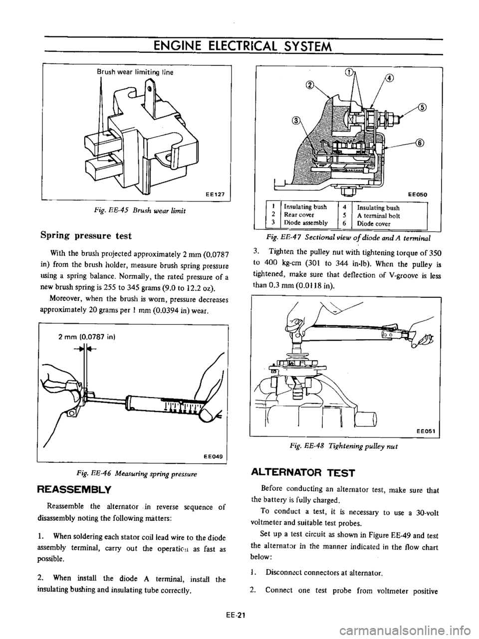
Spring
pressure
test
With
the
brush
projected
approximately
2
mm
0
0787
in
from
the
brush
holder
measure
brush
spring
pressure
using
a
spring
balance
Normally
the
rated
pressure
of
a
new
brush
spring
is
255
to
345
grams
9
0
to
12
2
oz
Moreover
when
the
brush
is
worn
pressure
decreases
approximately
20
grams
per
I
mm
0
0394
in
wear
2
rnm
0
0787
in
r
II
EEQ49
Fig
EE
46
Measuring
spring
pressure
REASSEMBLY
Reassemble
the
alternator
in
reverse
sequence
of
disassembly
noting
the
following
matters
I
When
soldering
each
stator
coil
lead
wire
to
the
diode
assembly
terminal
carry
out
the
operatic
as
fast
as
possible
2
When
install
the
diode
A
terminal
install
the
insulating
bushing
and
insulating
tube
correctly
EE
21
EE050
I
Insulating
bush
2
Rear
cover
3
Diode
assembly
4
Insulating
bush
5
A
terminal
bolt
6
Diode
cover
Fig
EE
47
Sectional
view
of
diode
and
A
terminal
3
Tighten
the
pulley
nut
with
tightening
torque
of
350
to
400
kg
cm
301
to
344
in
Ib
When
the
pulley
is
tightened
make
sure
that
deflection
of
V
groove
is
less
than
0
3
mm
0
0118
in
EE051
Fig
EE
4B
TiJ
htening
pulley
nut
ALTERNATOR
TEST
Before
conducting
an
alternator
test
make
sure
that
the
battery
is
fully
charged
To
conduct
a
test
it
is
necessary
to
use
a
3D
volt
voltmeter
and
suitable
test
probes
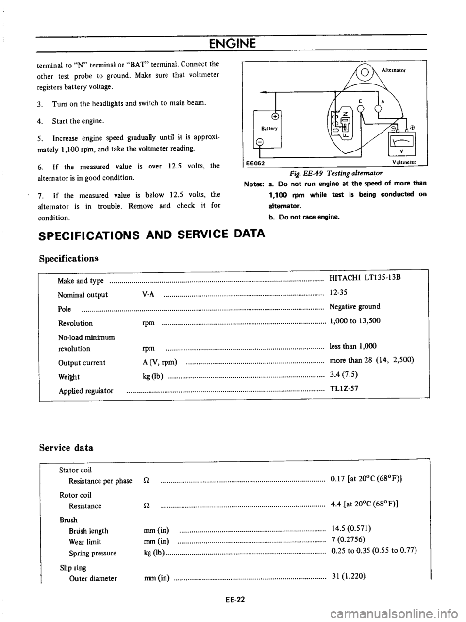
Set
up
a
test
circuit
as
shown
in
Figure
EE
49
and
test
the
alternator
in
the
manner
indicated
in
the
flow
chart
below
Disconn
ct
connectors
at
alternator
2
Connect
one
test
probe
from
voltmeter
positive
Page 442 of 513
ENGINE
terminal
to
IN
terminal
or
BAT
terminal
Connect
the
other
test
probe
to
ground
Make
sure
that
voltmeter
registers
battery
voltage
4
Start
the
engine
3
Turn
on
the
headlights
and
switch
to
main
beam
I
o
B
ttefY
E
A
J
0
il
I
5
Increase
engine
speed
gradually
until
it
is
approxi
mately
1
100
rpm
and
take
the
voltmeter
reading
6
If
the
measured
value
is
over
12
5
volts
the
alternator
is
in
good
condition
o
I
eE052
Voltmeter
Fig
EE
49
Testing
altematoT
Notes
8
Do
not
run
engine
at
the
speed
of
more
than
1
100
rpm
while
test
is
being
conducted
on
alternator
b
Do
not
race
engine
7
If
the
measured
value
is
below
12
5
volts
the
alternator
is
in
trouble
Remove
and
check
it
for
condition
SPECIFICATIONS
AND
SERVICE
DATA
Specifications
Make
and
type
Nominal
output
Pole
Revolution
No
load
minimum
revolution
Output
current
Wei
t
Applied
regulator
Service
data
Stator
coil
Resistance
per
phase
Rotor
coil
Resistance
Brush
Brush
length
Wear
limit
Spring
pressure
Slip
ring
Outer
diameter
V
A
HITACHI
LTl35
13B
12
35
rpm
Negative
ground
1
000
to
13
500
rpm
A
V
rpm
kg
1b
less
than
1
000
more
than
28
14
2
500
3
4
7
5
TLl
Z
57
n
0
17
at
200C
680F
n
4
4
at
200e
680
F
mm
in
mm
in
kg
lb
14
5
0
571
7
0
2756
0
25
to
0
35
0
55
to
0
77
mm
in
31
1
220
EE
22
Page 457 of 513
ENGINE
ElECTRICAL
SYSTEM
SPECIFICATIONS
Make
and
type
Primary
voltage
v
Spark
gap
mm
in
Primary
resistance
at
200C
680
F
n
Secondary
resistance
at
200C
680F
Kn
External
resistor
at
200C
680
F
n
Applied
resistor
HANSHIN
HITACHI
H5
15
2
C6R
601
12
12
more
than
7
more
than
7
0
28
0
28
1
17
to
I
43
l
l
7
to
I
43
11
2
to
16
8
11
2
to
16
8
l
3tol7
l
3tol7
RC
15
5560R
151O
SPARK
PLUG
CONTENTS
DESCRIPTION
INSPECTION
CLEANING
AND
REGAP
EE
37
EE
37
EE
38
DESCRIPTION
The
spark
plugs
are
of
the
resister
type
having
14
mm
0
551
in
threads
and
0
8
to
0
9
mm
0
031
to
0
Q35
in
gap
Note
All
spark
plugs
installed
on
an
engine
must
be
of
the
same
brand
and
number
of
heat
range
INSPECTION
1
Remove
spark
plug
wire
by
pulling
on
boot
not
on
wire
itself
2
Remove
spark
plugs
3
Check
electrodes
and
inner
and
outer
porcelains
of
plugs
noting
the
type
of
deposits
and
the
degree
of
electrode
erosion
Refer
to
Figure
EE
74
Normal
Brown
to
grayish
tan
deposits
and
slight
elec
trode
wear
indicate
correct
spark
plug
heat
range
SPECIFICATIONS
AND
SERVICE
DATA
TROUBLE
DIAGNOSES
AND
CORRECTIONS
EE
38
EE
39
Carbon
fouled
Dry
fluffy
carbon
deposits
on
the
insula
tor
and
electrode
were
mostly
caused
by
slow
speed
driving
in
city
weak
ignition
too
rich
fuel
mixture
dirty
air
cleaner
etc
H
is
advisable
to
replace
with
plugs
having
hotter
heat
range
Oil
fouled
Wet
black
deposits
show
excessive
oil
en
trance
into
combustion
chamber
through
worn
rings
and
pistons
or
excessive
clearance
between
valve
guides
and
stems
If
the
same
condition
remains
after
repair
use
a
hotter
plug
Overheating
White
or
light
gray
insulator
with
black
or
gray
brown
spots
and
bluish
burnt
electrodes
indicate
engine
overheating
Moreover
the
appearance
results
from
incorrect
ignition
timing
loose
spark
plugs
low
fuel
pump
pressure
wrong
selection
of
fuel
a
hotter
plug
etc
H
is
advisable
to
replace
with
plugs
having
colder
heat
range
EE
37
Page 467 of 513

CHASSIS
ENGINE
REMOVAL
AND
INSTALLATION
CONTENTS
PR
ECAUTIONS
REMOVAL
ERA
ERA
PRECAUTIONS
Be
sure
to
use
fender
cover
so
that
the
body
is
not
damaged
2
When
lifting
the
engine
or
when
jacking
up
the
engine
pay
attention
for
safety
and
carry
out
operation
correctly
so
that
the
parts
are
not
damaged
REMOVAL
I
Removing
hood
Open
the
hood
remove
four
installation
bolts
and
remove
the
hood
2
Disconnect
the
battery
cable
from
the
terminal
3
Removing
radiator
Drain
water
from
the
radiator
disconnect
two
radiator
hoses
remove
four
radiator
installation
bolts
and
remove
the
radiator
Fig
ER
8
Removin
radiator
4
Removing
cables
and
hoses
Disconnect
the
following
cables
hoses
and
wires
High
voltage
cable
between
ignition
coil
and
distribu
INSTAllATION
ER
6
tor
Cable
to
the
thermal
transmitter
Cable
to
the
oil
pressure
switch
Cable
to
the
primary
side
of
the
distributor
Cable
to
the
starting
motor
Fuel
hose
Cable
to
the
alternator
Heater
hose
for
model
with
heater
only
Wires
for
accelerator
and
choke
The
operation
will
be
carried
out
more
easily
by
removing
the
air
cleaner
Fig
ER
9
Right
side
of
engine
compartment
Fig
ER
10
Left
side
of
engine
compartment
ERA
Page 473 of 513
CLUTCH
2
Measuring
and
adjusting
height
of
diaphragm
spring
I
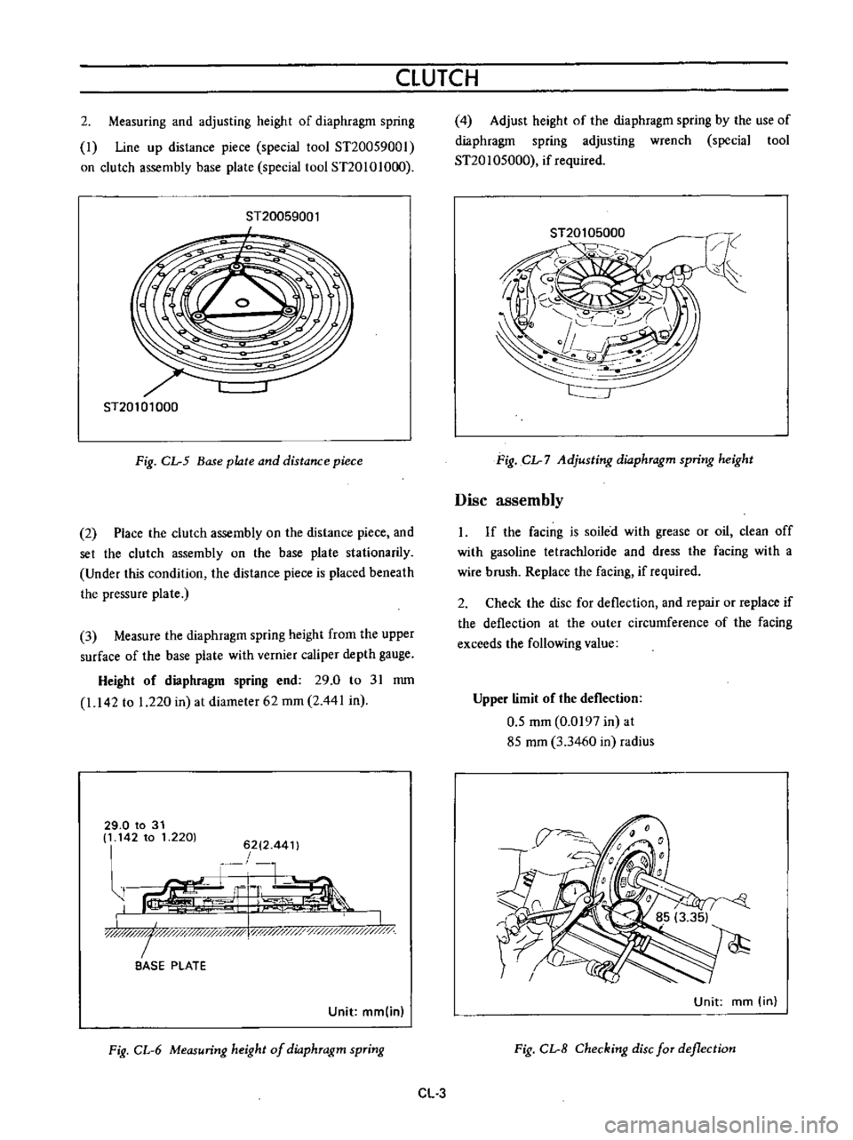
Line
up
distance
piece
special
tool
ST20059001
on
clutch
assembly
base
plate
special
tool
ST20101O
0
ST20059001
I
ST20101000
Fig
CL
5
Base
plate
and
distance
piece
2
Place
the
clutch
assembly
on
the
distance
piece
and
set
the
clutch
assembly
on
the
base
plate
stationarily
Under
this
condition
the
distance
piece
is
placed
beneath
the
pressure
plate
3
Measure
the
diaphragm
spring
height
from
the
upper
surface
of
the
base
plate
with
vernier
caliper
depth
gauge
Height
of
diaphragm
spring
end
29
0
to
31
mm
1
142
to
1
220
in
at
diameter
62
mm
2
441
in
29
0
to
31
It
142
to
1
2201
6212
44
t
r
1
G
L
ir
I
LJIlW
I
y
y
x
l
i
0
BASE
PLATE
Unit
mm
in
Fig
CL
6
Measuring
height
of
dio
phTagm
spTing
4
Adjust
height
of
the
diaphragm
spring
by
the
use
of
diaphragm
spring
adjusting
wrench
special
tool
ST20
1
05000
if
required
Fig
CL
7
Adjusting
dio
phTagm
spring
height
Disc
assembly
If
the
facing
is
soiled
with
grease
or
oil
clean
off
with
gasoline
tetracWoride
and
dress
the
facing
with
a
wire
brush
Replace
the
facing
if
required
2
Check
the
disc
for
deflection
and
repair
or
replace
if
the
deflection
at
the
outer
circumference
of
the
facing
exceeds
the
following
value
Upper
limit
of
the
deflection
0
5
mm
0
0197
in
at
85
mm
3
3460
in
radius
Unit
mm
in
Fig
CL
8
Checking
disc
fOT
deflection
CL
3
Page 484 of 513
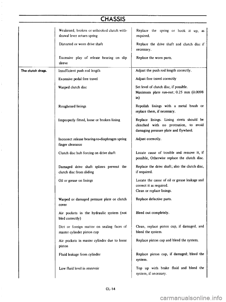
The
clutch
drags
CHASSIS
Weakened
broken
ur
unhooked
clutch
with
drawallever
return
spring
Distorted
or
worn
drive
shaft
Excessive
play
of
release
bearing
on
slip
sleeve
Insufficient
push
rod
length
Excessive
pedal
free
travel
Warped
clutch
disc
Roughened
linings
Improperly
fitted
loose
or
broken
lining
Incorrect
release
bearing
to
diaphragm
spring
fmger
clearance
Clutch
disc
hub
forcing
on
drive
shaft
Damaged
drive
shaft
splines
prevent
the
clutch
disc
from
sliding
Oil
or
grease
on
linings
Warped
or
damaged
pressure
plate
or
clutch
cover
Air
pockets
in
the
hydraulic
system
not
bled
correctly
Dirt
or
foreign
matter
on
sealing
faces
of
master
cylinder
piston
cup
Air
pockets
in
master
cylinder
due
to
loose
piston
Fluid
leakage
from
cylinder
Low
fluid
level
in
reservoir
CL14
Replace
the
spring
or
hook
it
up
as
required
Replace
the
drive
shaft
and
clutch
disc
if
necessary
Replace
the
worn
parts
Adjust
the
push
rod
length
correctly
Adjust
free
travel
correctly
Set
level
of
clutch
disc
if
possible
Maximum
plate
run
out
0
25
mm
0
0098
in
Repolish
linings
with
a
metal
brush
or
replace
them
if
necessary
Replace
linings
Lining
rivets
should
be
clenched
with
no
protrusion
to
avoid
damaging
pressure
plate
and
flywheel
Adjust
correctly
Locate
cause
of
trouble
and
remove
it
if
possible
Otherwise
replace
the
clutch
disc
Replace
the
drive
shaft
also
the
clutch
disc
if
required
Locate
the
cause
of
oil
or
grease
leakage
and
correct
it
as
required
Clean
or
replace
linings
Replace
defective
parts
Bleed
out
completely
Clean
replace
piston
cup
if
damaged
and
bleed
the
system
Replace
piston
cup
and
bleed
the
system
Replace
piston
cup
if
damaged
bleed
the
system
Top
up
with
brake
fluid
and
bleed
the
system
if
necessary
Page 485 of 513
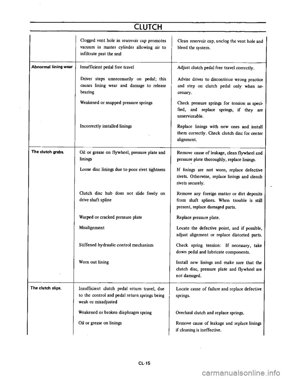
CLUTCH
Clogged
vent
hole
in
reservoir
cap
promotes
vacuum
in
master
cylinder
allowing
air
to
inf1ltrate
past
the
seal
Abnormal
lining
wear
Insufficient
pedal
free
travel
The
clutch
grabs
The
clutch
slips
Driver
steps
unnecessarily
on
pedal
this
causes
lin
jog
wear
and
damage
to
release
bearing
Weakened
or
snapped
pressure
springs
Incorrectly
installed
linings
Oil
or
grease
on
flywheel
pressure
plate
and
linings
Loose
disc
linings
due
to
poor
rivet
tightness
Clutch
disc
hub
does
not
slide
freely
on
drive
shaft
spline
Warped
or
cracked
pressure
plate
Misalignment
Stiffened
hydraulic
control
mechanism
Wom
out
lining
Insufficient
clutch
pedal
return
travel
due
to
the
control
and
pedal
return
springs
being
weak
or
misadjusted
Weakened
or
broken
diaphragm
spring
Oil
or
grease
on
linings
eLl5
Clean
reservoir
cap
unclog
the
vent
hole
and
bleed
the
system
Adjust
clutch
pedal
free
travel
correctly
Advise
driver
to
discontinue
wrong
practice
and
step
on
clutch
pedal
only
when
ne
cessary
Check
pressure
springs
for
tension
as
speci
fied
and
replace
springs
if
they
are
unserviceable
Replace
linings
with
new
ones
and
install
them
correctly
Check
clutch
disc
for
center
alignment
Remove
cause
of
leakage
clean
flywheel
and
pressure
plate
thoroughly
replace
linings
If
linings
are
not
worn
replace
defective
rivets
Otherwise
replace
linings
and
clench
rivets
securely
Remove
any
foreign
matter
or
dirt
deposits
from
shaft
splines
When
trouble
is
still
present
replace
damaged
parts
Replace
pressure
plate
Locate
the
defective
point
and
if
possible
adjust
alignment
or
replace
distorted
parts
Check
spring
tension
If
necessary
take
down
pedal
and
lubricate
components
Install
new
linings
and
make
sure
tha
t
the
clutch
disc
pressure
plate
and
flywheel
are
not
damaged
Locate
cause
of
failure
and
replace
defective
springs
Overhaul
clutch
and
replace
springs
Remove
cause
of
leakage
and
replace
linings
if
cleaning
is
ineffective