1973 DATSUN B110 low oil pressure
[x] Cancel search: low oil pressurePage 331 of 513

ENGINE
Spark
plugs
Cap
mm
in
0
8
to
0
9
0
03110
0
035
Idle
CO
ldie
speed
Manual
transmission
rpm
rpm
1
5
to
5
800
1
5
to
5
650
in
D
position
Automatic
transmission
Dash
pot
Setting
engine
speed
rpm
1
900
to
2
000
Throttle
opener
at
sea
level
Setting
vacuwn
pressure
Manual
transmission
Automatic
transmission
Setting
engine
speed
no
load
Servo
diaphragm
full
stroke
rpm
mm
in
500
to
540
19
7
to
21
3
480
to
520
18
9
to
20
5
1
650
to
1
850
5
0
1969
mmHg
in
Hg
mmHg
in
Hg
Theono
switch
Temperature
rises
from
low
to
high
oC
0
F
above
5
41
Flow
guide
valve
Opera
ting
pressure
mmHg
in
Hg
10
0
4
TROUBLE
DIAGNOSES
AND
CORRECTIONS
Troubles
Possible
causes
Remedies
CANNOT
CRANK
ENGINE
OR
SLOW
CRANKING
Improper
grade
oiL
Replace
with
proper
grade
oiL
Discharged
battery
Charge
battery
Defective
battery
Replace
Loosen
fan
belt
Adjust
Trouble
in
charge
system
Inspect
charge
system
Wiring
connection
trouble
in
starting
circuit
Correct
Defective
starter
switch
Repair
or
replace
Defective
starter
motor
Repair
or
replace
ET
26
I
Page 335 of 513
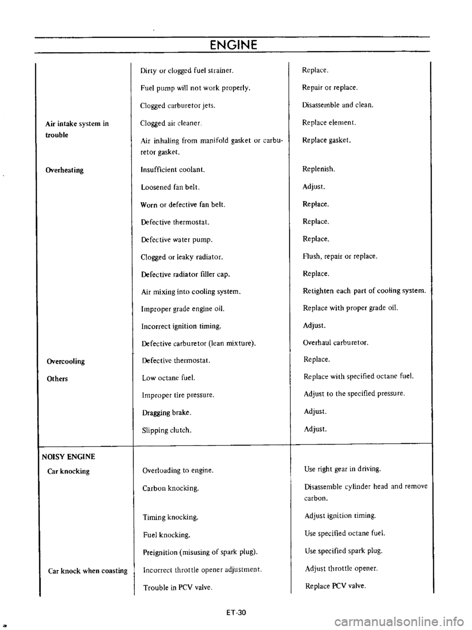
Air
intake
system
in
trouble
Overheating
Overcooling
Others
NOISY
ENGINE
Car
knocking
Car
knock
when
coasting
ENGINE
Diny
ur
clogged
fuel
strainer
Fuel
pump
will
not
work
properly
Clogged
carburetor
jets
Clogged
air
cleaner
Air
inhaling
from
manifold
gasket
or
carbu
retor
gasket
Insufficient
coolant
Loosened
fan
belt
Worn
or
defective
fan
belt
Defective
thermostat
Defective
water
pump
Clogged
or
leaky
radiator
Defective
radiator
filler
cap
Air
mixing
into
cooling
system
Improper
grade
engine
oil
Incorrect
ignition
timing
Defective
carburetor
lean
mixture
Defective
thermostat
Low
octane
fuel
Improper
tire
pressure
Dragging
brake
Slipping
clutch
Overloading
to
engine
Carbon
knocking
Timing
knocking
Fuel
knocking
Preignition
misusing
of
spark
plug
Incorrect
throttle
opener
adjustment
Trouble
in
PCV
valve
ET
30
Replace
Repair
or
replace
Disassemble
and
clean
Replace
element
Replace
gasket
Replenish
Adjust
Replace
Replace
Replace
Flush
repair
or
replace
Replace
Retighten
each
part
of
cooling
system
Replace
with
proper
grade
oil
Adjust
Overhaul
carburetor
Replace
Replace
with
specified
octane
fuel
Adjust
to
the
specified
pressure
Adjust
Adjust
Use
right
gear
in
driving
Disassemble
cylinder
head
and
remove
carbon
Adjust
ignition
timing
Use
specified
octane
fuel
Use
specified
spark
plug
Adjust
throttle
opener
Replace
PCV
valve
Page 342 of 513
ENGINE
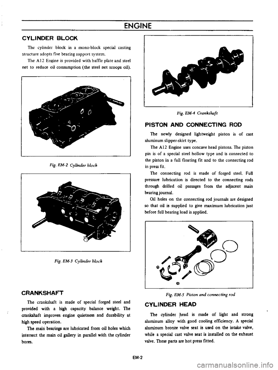
CYLINDER
BLOCK
The
cylinder
block
in
a
mono
block
special
casting
structure
adopts
five
bearing
support
system
The
A
12
Engine
is
provided
with
baffle
plate
and
steel
net
to
reduce
oil
consumption
the
steel
net
scoops
oil
j
y
r
0
Q
0
T
Fig
EM
2
Cylinder
block
Fig
EM
3
Cylinder
block
CRANKSHAFT
The
crankshaft
is
made
of
special
forged
steel
and
provided
with
a
high
capacity
balance
weight
The
crankshaft
improves
engine
quietness
and
durability
t
high
speed
operation
The
main
bearing
are
lubricated
from
oil
holes
which
intersect
the
main
oil
gallery
in
parallel
with
the
cylinder
bores
v
Fig
EM
4
Crankshaft
PISTON
AND
CONNECTING
ROD
The
newly
designed
lightweight
piston
is
of
cast
aluminum
slipper
skirt
type
The
A
12
Engine
uses
concave
head
pistons
The
piston
pin
is
of
a
special
steel
hollow
type
and
is
connected
to
the
piston
in
a
full
floating
fit
and
to
the
connecting
rod
in
press
fit
The
connecting
rod
is
made
of
forged
steeL
Full
pressure
lubrication
is
directed
to
the
connecting
rods
through
drilled
oil
passages
from
the
adjacent
main
bearing
journal
Oil
holes
on
the
connecting
rod
journals
are
designed
so
that
oil
is
supplied
to
give
maximum
lubrication
just
before
full
bearing
load
is
applied
J
oO
o
e
Fig
EM
5
Piston
and
connecting
rod
CYLINDER
HEAD
The
cylinder
head
is
made
of
light
and
strong
aluminum
alloy
with
good
cooling
efficiency
A
special
aluminum
bronze
valve
seat
is
used
on
the
intake
valve
while
a
special
cast
valve
seat
is
installed
on
the
exhaust
valve
These
parts
are
hot
press
fitted
EM
2
Page 343 of 513
ENGINE
MECHANICAL
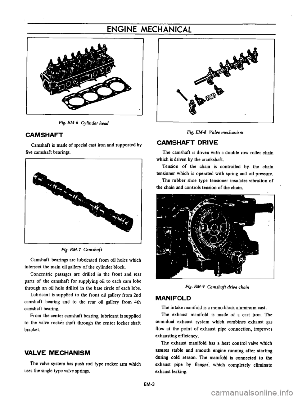
Fig
EM
6
Cylinder
head
CAMSHAFT
Camshaft
is
made
of
special
cast
iron
and
supported
by
five
cannshaft
bearings
1
1
f
r
f
r
I
Fig
EM
Camshaft
Camshaft
bearings
are
lubricated
from
oil
holes
which
intersect
the
main
oil
gallery
of
the
cylinder
block
Concentric
passages
are
drilled
in
the
front
and
rear
parts
of
the
camshaft
for
supplying
oil
to
each
cam
lobe
through
an
oil
hole
drilled
in
the
base
circle
of
each
lobe
Lubricant
is
supplied
to
the
front
oil
gallery
from
2nd
camshaft
bearing
and
to
the
rear
oil
gallery
from
4th
camshaft
bearing
From
the
center
camshaft
bearing
lubricant
is
supplied
to
the
valve
rocker
shaft
through
the
center
locker
shaft
bracket
VALVE
MECHANISM
The
valve
system
has
push
rod
type
rocker
arm
which
uses
the
single
type
valve
springs
a
Fig
EM
8
Vol
mechanism
CAMSHAFT
DRIVE
The
camshaft
is
driven
with
a
double
row
roller
chain
which
is
driven
by
the
crankshaft
Tension
of
the
chain
is
controlled
by
the
chain
tensioner
which
is
operated
with
spring
and
oil
pressure
The
rubber
shoe
type
tensioner
insulates
vibration
of
the
chain
and
controls
tension
of
the
chain
Fig
EM
9
Comshdft
drive
chain
MANIFOLD
The
intake
manifold
is
a
mono
block
aluminum
cast
The
exhaust
manifold
is
made
of
a
cast
iron
The
semi
dual
exhaust
system
which
combines
exhaust
gas
flow
at
the
point
of
exhaust
pipe
connection
improves
exhausting
efficiency
The
exhaust
manifold
has
a
heat
control
valve
which
assures
stable
and
smooth
engine
running
after
starting
during
cold
season
The
manifold
is
connected
to
the
exhaust
pipe
by
flanges
which
completely
eliminate
exhaust
leaking
EM
3
Page 380 of 513
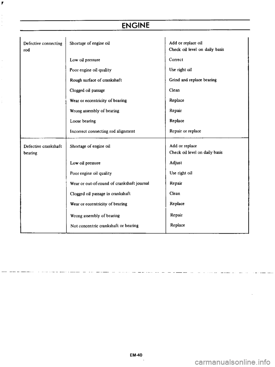
r
Defective
connecting
rod
Defective
crankshaft
bearing
ENGINE
Shortage
of
engine
oil
Low
oil
pressure
Poor
engine
oil
quslity
Rough
surface
of
crankshaft
Clogged
oil
passage
Wear
or
eccentricity
of
bearing
Wrong
assembly
of
bearing
Loose
bearing
Incorrect
connecting
rod
alignment
Shortage
of
engine
oil
Low
oil
pressure
Poor
engine
oil
quality
Wear
or
out
of
round
of
crankshaft
journal
Clogged
oil
passage
in
crankshaft
Wear
or
eccentricity
of
bearing
Wrong
assembly
of
bearing
Not
concentric
crankshaft
or
bearing
EM
40
Add
or
replace
oil
Check
oil
level
on
daily
basis
Correct
Use
right
oil
Grind
and
replace
bearing
Clean
Replace
Repair
Replace
Repair
or
replace
Add
or
replace
Check
oil
level
on
daily
basis
Adjust
Use
right
oil
Repair
Clean
Replace
Repair
Replace
Page 383 of 513
LUBRICATION
CIRCUIT
Oil
drawn
from
the
oil
pan
through
the
inlet
screen
and
tube
to
the
inlet
side
of
the
oil
pump
is
delivered
by
th
oil
pump
through
the
outlet
portion
of
the
oil
pump
and
the
oil
gallery
to
the
inlet
side
of
the
full
flow
oil
filter
and
to
the
main
oil
gallery
The
main
oil
gallery
supplies
oil
to
the
crankshaft
main
bearings
and
drilled
passages
in
the
crankshaft
and
thus
oil
is
fed
directly
from
the
main
bearings
to
the
connecting
rod
bearings
Oil
injected
from
jet
holes
on
connecting
rods
lubri
cates
the
cylinder
walls
and
pistion
pins
The
oil
distributed
from
the
main
gallery
enters
the
chain
teosioner
and
the
pad
is
held
against
the
chain
by
oil
pressure
and
spring
The
oil
also
lubricates
the
timing
chain
through
the
jet
hole
located
near
the
chain
Furthermore
lubricant
is
supplied
to
each
camshaft
bearing
through
each
crankshaft
main
bearing
and
finally
to
the
011
gallery
in
the
rocker
shaft
through
the
center
camshaft
bearing
The
rocker
arm
and
valve
are
lubricated
by
the
oil
through
the
oil
gallery
in
the
rockershaft
To
this
oil
gallery
lubricant
is
supplied
through
the
center
camshaft
bearing
as
shown
in
Figure
EL
I
OIL
PUMP
Description
The
oil
pump
assembly
is
installed
on
the
bottom
of
the
cylinder
block
and
driven
by
the
distributor
drive
shaft
assembly
The
oil
pump
is
of
a
rotor
type
The
oil
pressure
is
regulated
by
the
regulator
valve
camshaft
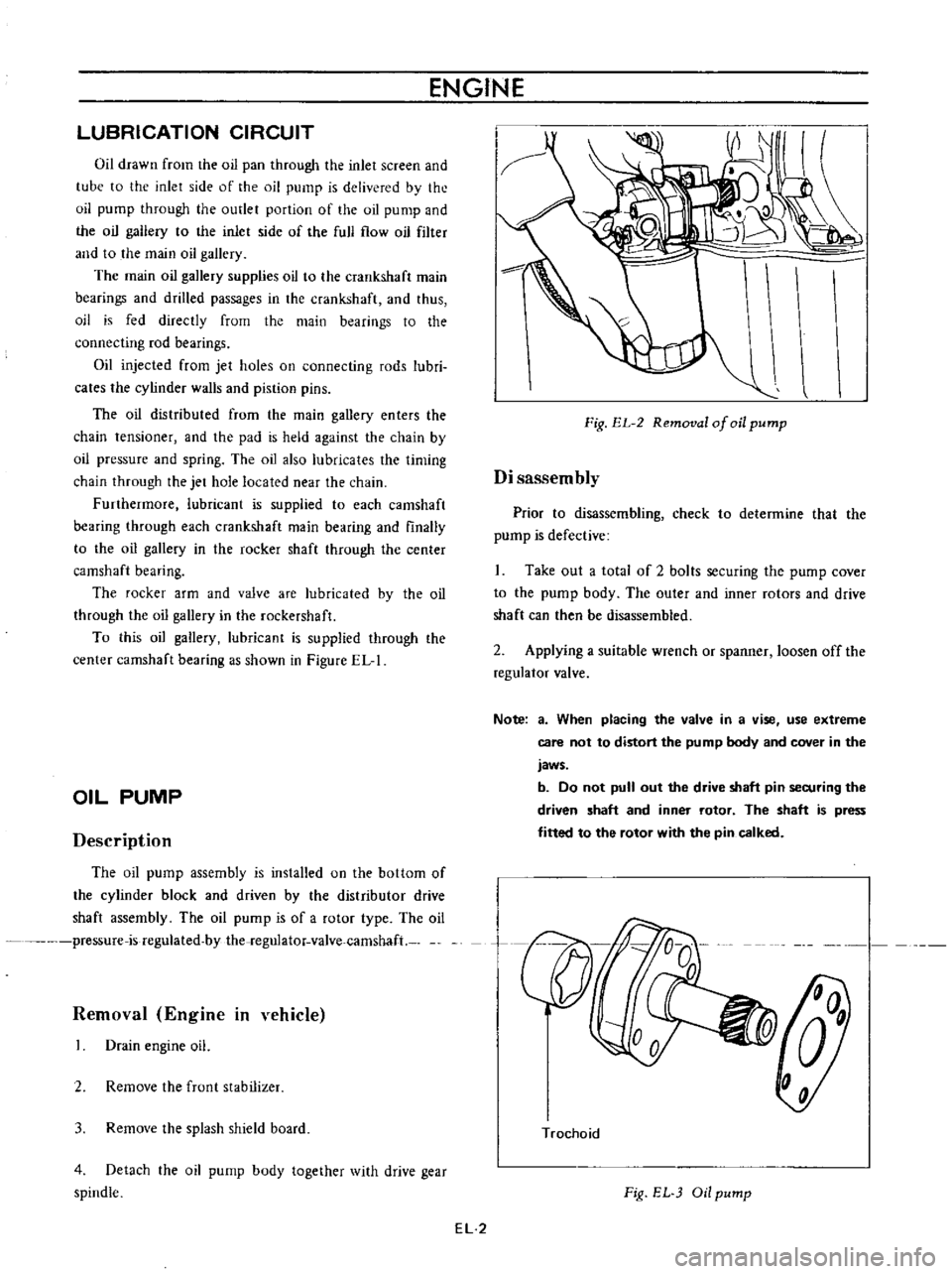
Removal
Engine
in
vehicle
Drain
engine
oil
2
Remove
the
frunt
stabilizer
3
Remove
the
splash
shield
board
4
Detach
the
oil
pump
body
together
with
drive
gear
spindle
ENGINE
Fig
EL
2
Removal
of
oil
pump
Disassembly
Prior
to
disassembling
check
to
determine
that
the
pump
is
defective
Take
out
a
total
of
2
bolts
securing
the
pump
cover
to
the
pump
body
The
outer
and
inner
rotors
and
drive
shaft
can
then
be
disassembled
2
Applying
a
suitable
wrench
or
spanner
loosen
off
the
regulator
valve
Note
a
When
placing
the
valve
in
a
vise
use
extreme
care
not
to
distort
the
pump
body
and
cover
in
the
jaws
b
Do
not
pull
out
the
drive
shaft
pin
securing
the
driven
shaft
and
inner
rotor
The
shaft
is
press
fitted
to
the
rotor
with
the
pin
calked
n
Trochoid
Fig
EL
Oil
pump
EL
2
Page 384 of 513
ENGINE
LUBRICATION
SYSTEM
Inspection
and
repair
Clean
the
disassembled
parts
with
cleaning
solvent
and
inspect
for
defects
Inspect
the
drive
rotor
shaft
for
excessive
wear
and
scores
and
check
the
following
clearances
Side
clearance
between
Quter
and
inner
rotors
0
12
mm
0
0047
in
or
below
Tip
clearance
0
04
to
0
I2mm
0
0016
to
0
0047
in
Clearance
between
outer
rotor
and
body
0
15
to
0
21
rom
0
0059
to
0
0083
in
Adjusting
regulator
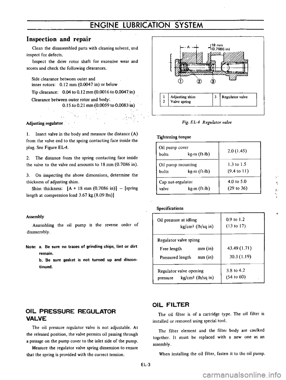
Insert
valve
in
the
body
and
measure
the
distance
A
from
the
valve
end
to
the
spring
contacting
face
inside
the
plug
See
Figure
EL
4
2
The
distance
from
the
spring
contacting
face
inside
the
valve
to
the
valve
end
amounts
to
18
mm
0
7086
in
3
On
inspecting
the
above
dimensions
determine
the
thickness
of
adjusting
shim
Shim
thickness
A
18
mm
0
7086
in
spring
length
at
compression
load
3
67
kg
8
091bs
Assembly
Assembling
the
oil
pump
is
the
reverse
order
of
disassembly
Note
3
Be
sure
no
traces
of
grinding
chips
lint
or
dirt
remain
b
Be
sure
gasket
is
not
turned
up
and
discon
tinued
OIL
PRESSURE
REGULATOR
VALVE
The
oil
pressure
regulator
valve
is
not
adjustable
At
the
released
position
the
valve
permits
oil
passing
through
a
passage
on
the
pump
cover
to
the
inlet
side
of
the
pump
Measure
the
regulator
valve
spring
dimension
to
ensure
that
the
spring
is
provided
with
the
correct
tension
e
Q
@
I
I
Adjusting
shim
2
Valve
spring
13
I
RegulatoT
valve
Fig
EL
4
RegulatoT
valve
Tightening
torque
Oil
pump
cover
bolts
kg
m
ft
lb
2
0
1
45
Oil
pump
mounting
bolts
kg
m
ft
lb
13
to
1
5
9
4to
II
Cap
nut
regulator
valve
kg
m
ft
lb
4
0
to
5
0
29
to
36
Specifications
Oil
pressure
at
idling
kgfcm2
Ibfsq
in
0
9
to
1
2
13
to
17
Regulator
valve
spirng
Free
length
mm
in
Pressured
length
mm
in
4349
l71
30
3
I
19
Regulator
valve
opening
pressure
kgfcm2
lbfsq
in
3
8
to
4
2
54
to
60
OIL
FILTER
The
oil
filter
is
of
a
cartridge
type
The
oil
filter
is
installed
or
removed
using
special
tool
The
filter
element
and
the
filter
body
are
caulked
together
I
t
must
be
replaced
with
a
new
one
as
an
assembly
When
installing
the
oil
filter
fasten
it
to
the
oil
pump
EL
3
Page 434 of 513

Pinion
intermeshes
with
ring
gear
Starting
motor
rotates
and
pinion
intermeshes
with
ring
gear
but
ro
tation
is
too
slow
When
starting
switch
is
set
to
OFF
the
start
ing
motor
does
not
stop
Starting
motor
Battery
Wiring
Ignition
switch
Starting
motor
Ignition
switch
Magnetic
switch
Starting
motor
ENGINE
Faulty
pinion
sliding
Dropped
off
lever
pin
Excessive
plunger
L
dimension
Defective
over
running
clutch
Over
discharging
Improper
or
loose
terminal
contact
Improperly
tightened
connection
Rough
contact
surface
Shorted
armature
coil
or
field
coil
Worn
brush
or
insufficient
spring
pressure
Contaminated
commutator
or
im
proper
brush
contact
Defective
mica
Lack
of
metal
lubrication
Armature
contacted
with
pole
core
Faulty
returning
Seized
contact
Shorted
coil
Faulty
plunger
sliding
Pinion
does
not
disengage
from
the
ring
gear
smoothly
Pinion
spline
does
not
disengage
smoothly
Seized
pinion
metal
EE
14
Repair
Repair
Adjust
Replace
Charge
battery
Repair
and
retighten
Retighten
Repair
or
replace
Repair
or
replace
Repair
or
replace
Repair
Repair
Repair
or
replace
Repair
or
replace
Replace
Replace
Replace
Replace
Repair
or
replace
Repair
or
replace
Replace