1973 DATSUN B110 clutch
[x] Cancel search: clutchPage 482 of 513
CHASSIS
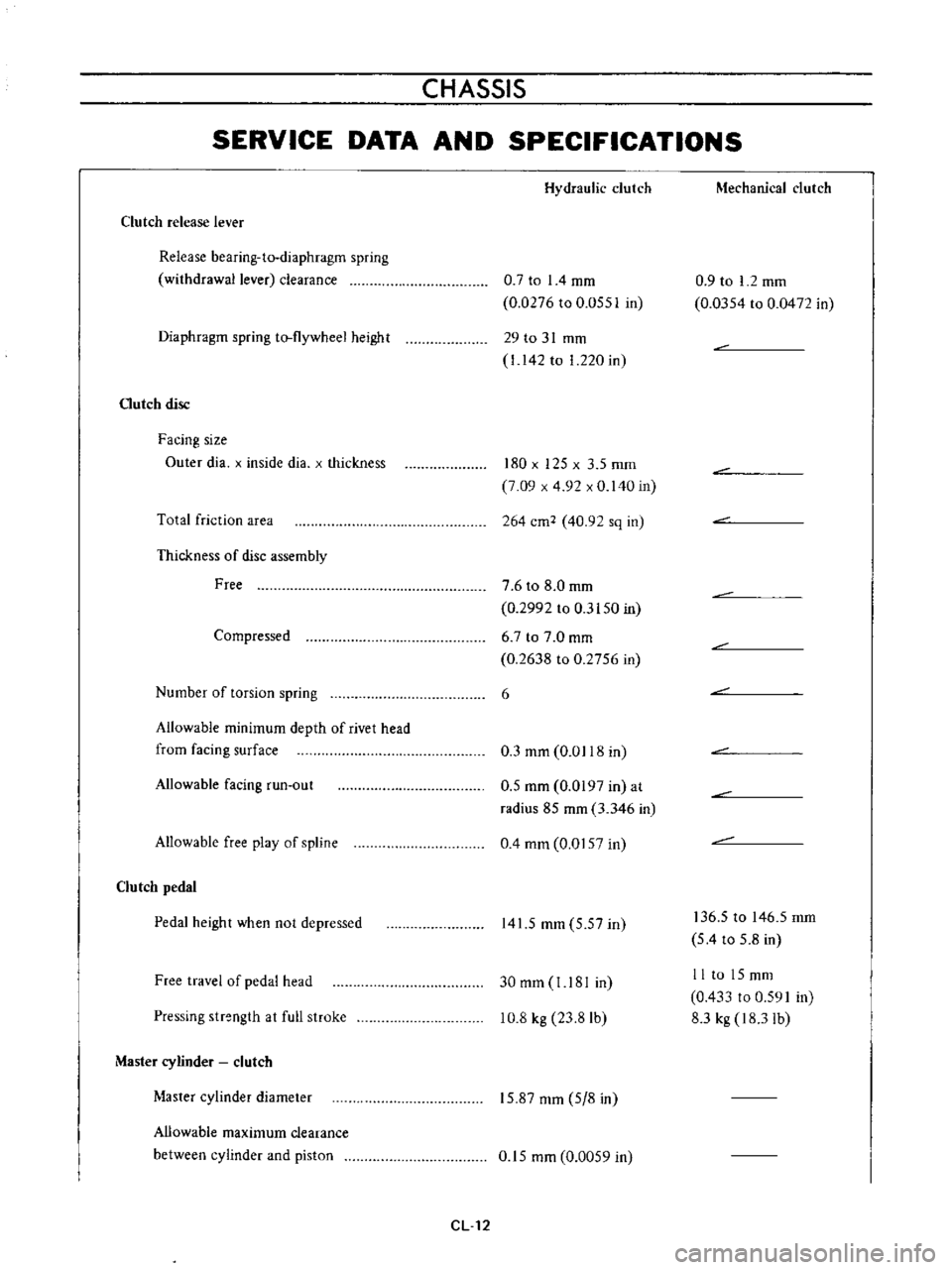
SERVICE
DATA
AND
SPECIFICATIONS
Clutch
release
lever
Release
bearing
ta
diaphragm
spring
withdrawal
lever
clearance
Diaphragm
spring
to
flywheel
height
Gutch
disc
Facing
size
Outer
dia
x
inside
dia
x
thickness
Total
friction
area
Thickness
of
disc
assembly
Free
Compressed
Number
of
torsion
spring
Allowable
minimum
depth
of
rivet
head
from
facing
surface
Allowable
facing
run
out
Allowable
free
play
of
spline
Clutch
pedal
Pedal
height
when
not
depressed
Free
travel
of
pedal
head
Pressing
strength
at
full
stroke
Master
cylinder
clutch
Master
cylinder
diameter
Allowable
maximum
clearance
between
cylinder
and
piston
Hydraulic
clutch
0
7
to
I
4
mm
0
0276
to
0
055
in
29
to
31
mm
I
142
to
1
220
in
180
x
125
x
3
5
mm
7
09
x
4
92
x
0
140
in
264
cm2
40
92
sq
in
7
6
to
8
0
mm
0
2992
to
0
3150
in
6
7
to
7
0
mm
0
2638
to
0
2756
in
6
0
3
mm
0
0118
in
0
5
mm
0
0197
in
at
radius
85
mm
3
346
in
0
4
mm
0
0157
in
141
5
mm
5
57
in
30
mm
J
181
in
10
8
kg
23
8
Ib
15
87
mm
5
8
in
0
15
mm
0
0059
in
CL12
Mechanical
clutch
0
9
to
I
2
mm
0
0354
to
0
0472
in
136
5
to
146
5
mm
5
4
to
5
8
in
II
to
15mm
0
433
to
0
591
in
8
3
kg
18
31b
Page 483 of 513
CLUTCH
Operating
cylinder
clutch
Operating
cylinder
diameter
T
Ilhtening
torque
19
05
mm
0
750
in
Clutch
assembly
securing
bolt
1
5
to
2
2
kg
m
10
8
to
15
9
ft
Ib
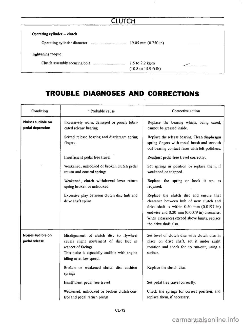
TROUBLE
DIAGNOSES
AND
CORRECTIONS
Condition
Noises
audible
on
pedal
depression
Noises
audible
on
pedal
release
Probable
cause
Excessively
worn
damaged
or
poorly
lubri
cated
release
bearing
Seized
release
bearing
and
diaphragm
spring
fingers
Insufficient
pedal
free
travel
Weakened
unhooked
or
broken
clutch
pedal
return
and
control
springs
Weakened
clutch
withdrawal
lever
return
spring
broken
or
unhooked
Excessive
play
between
clutch
disc
hub
and
drive
shaft
spline
Misalignment
of
clutch
disc
to
flywheel
causes
slight
movement
of
disc
hub
in
respect
of
facings
This
noise
is
especially
audible
with
engine
idling
or
at
low
speed
Broken
or
weakened
clutch
disc
cushion
springs
Insufficient
pedal
free
travel
Weakened
unhooked
or
broken
clutch
con
trol
and
pedal
return
prings
CL
13
Corrective
action
Replace
the
bearing
which
being
cased
cannot
be
greased
inside
Replace
the
release
bearing
Clean
diaphragm
spring
fingers
with
metal
brush
and
smooth
out
bearing
contact
faces
with
felt
polishers
Readjust
pedal
free
travel
correctly
Set
springs
in
position
or
replace
them
if
weakened
or
snapped
Replace
the
spring
or
hook
it
up
as
required
Replace
the
clutch
disc
and
ensure
that
clearance
between
hub
of
new
clutch
and
drive
shaft
is
within
0
50
mm
0
0197
in
endwise
and
0
20
mm
0
0079
in
crosswise
When
clearances
exceed
above
limits
replace
the
drive
shaft
also
Set
level
of
clutch
disc
with
clutch
disc
in
place
on
drive
shaft
set
it
under
slight
rotation
and
check
for
no
run
out
using
a
scriber
Replace
the
clutch
disc
Set
pedal
free
travel
correctly
Check
the
springs
for
correct
position
and
replace
them
if
necessary
Page 484 of 513
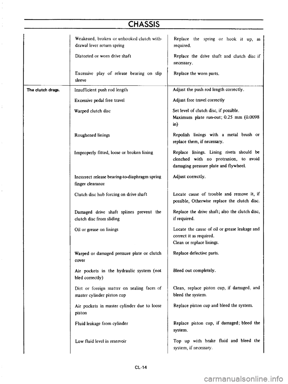
The
clutch
drags
CHASSIS
Weakened
broken
ur
unhooked
clutch
with
drawallever
return
spring
Distorted
or
worn
drive
shaft
Excessive
play
of
release
bearing
on
slip
sleeve
Insufficient
push
rod
length
Excessive
pedal
free
travel
Warped
clutch
disc
Roughened
linings
Improperly
fitted
loose
or
broken
lining
Incorrect
release
bearing
to
diaphragm
spring
fmger
clearance
Clutch
disc
hub
forcing
on
drive
shaft
Damaged
drive
shaft
splines
prevent
the
clutch
disc
from
sliding
Oil
or
grease
on
linings
Warped
or
damaged
pressure
plate
or
clutch
cover
Air
pockets
in
the
hydraulic
system
not
bled
correctly
Dirt
or
foreign
matter
on
sealing
faces
of
master
cylinder
piston
cup
Air
pockets
in
master
cylinder
due
to
loose
piston
Fluid
leakage
from
cylinder
Low
fluid
level
in
reservoir
CL14
Replace
the
spring
or
hook
it
up
as
required
Replace
the
drive
shaft
and
clutch
disc
if
necessary
Replace
the
worn
parts
Adjust
the
push
rod
length
correctly
Adjust
free
travel
correctly
Set
level
of
clutch
disc
if
possible
Maximum
plate
run
out
0
25
mm
0
0098
in
Repolish
linings
with
a
metal
brush
or
replace
them
if
necessary
Replace
linings
Lining
rivets
should
be
clenched
with
no
protrusion
to
avoid
damaging
pressure
plate
and
flywheel
Adjust
correctly
Locate
cause
of
trouble
and
remove
it
if
possible
Otherwise
replace
the
clutch
disc
Replace
the
drive
shaft
also
the
clutch
disc
if
required
Locate
the
cause
of
oil
or
grease
leakage
and
correct
it
as
required
Clean
or
replace
linings
Replace
defective
parts
Bleed
out
completely
Clean
replace
piston
cup
if
damaged
and
bleed
the
system
Replace
piston
cup
and
bleed
the
system
Replace
piston
cup
if
damaged
bleed
the
system
Top
up
with
brake
fluid
and
bleed
the
system
if
necessary
Page 485 of 513
CLUTCH
Clogged
vent
hole
in
reservoir
cap
promotes
vacuum
in
master
cylinder
allowing
air
to
inf1ltrate
past
the
seal
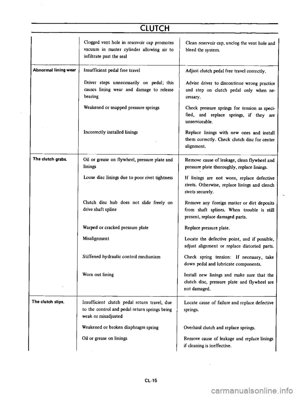
Abnormal
lining
wear
Insufficient
pedal
free
travel
The
clutch
grabs
The
clutch
slips
Driver
steps
unnecessarily
on
pedal
this
causes
lin
jog
wear
and
damage
to
release
bearing
Weakened
or
snapped
pressure
springs
Incorrectly
installed
linings
Oil
or
grease
on
flywheel
pressure
plate
and
linings
Loose
disc
linings
due
to
poor
rivet
tightness
Clutch
disc
hub
does
not
slide
freely
on
drive
shaft
spline
Warped
or
cracked
pressure
plate
Misalignment
Stiffened
hydraulic
control
mechanism
Wom
out
lining
Insufficient
clutch
pedal
return
travel
due
to
the
control
and
pedal
return
springs
being
weak
or
misadjusted
Weakened
or
broken
diaphragm
spring
Oil
or
grease
on
linings
eLl5
Clean
reservoir
cap
unclog
the
vent
hole
and
bleed
the
system
Adjust
clutch
pedal
free
travel
correctly
Advise
driver
to
discontinue
wrong
practice
and
step
on
clutch
pedal
only
when
ne
cessary
Check
pressure
springs
for
tension
as
speci
fied
and
replace
springs
if
they
are
unserviceable
Replace
linings
with
new
ones
and
install
them
correctly
Check
clutch
disc
for
center
alignment
Remove
cause
of
leakage
clean
flywheel
and
pressure
plate
thoroughly
replace
linings
If
linings
are
not
worn
replace
defective
rivets
Otherwise
replace
linings
and
clench
rivets
securely
Remove
any
foreign
matter
or
dirt
deposits
from
shaft
splines
When
trouble
is
still
present
replace
damaged
parts
Replace
pressure
plate
Locate
the
defective
point
and
if
possible
adjust
alignment
or
replace
distorted
parts
Check
spring
tension
If
necessary
take
down
pedal
and
lubricate
components
Install
new
linings
and
make
sure
tha
t
the
clutch
disc
pressure
plate
and
flywheel
are
not
damaged
Locate
cause
of
failure
and
replace
defective
springs
Overhaul
clutch
and
replace
springs
Remove
cause
of
leakage
and
replace
linings
if
cleaning
is
ineffective
Page 490 of 513
TRANSMISSION
I
Jack
up
the
vehicle
and
support
it
with
four
stands
If
available
recommend
a
hydraulic
hoist
or
open
pit
be
utilized
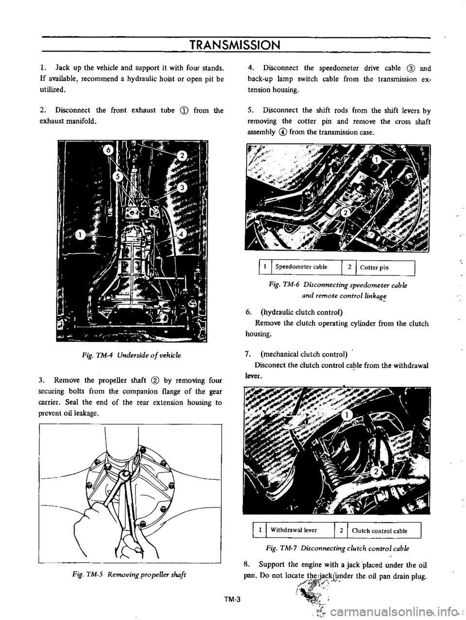
2
Disconnect
the
front
exhaust
tube
D
from
the
exhaust
manifold
Fig
TM
4
Underside
of
vehiJ
1e
3
Remove
the
propeller
shaft
@
by
removing
four
securing
bolts
from
the
companion
flange
of
the
gear
carrier
Seal
the
end
of
the
rear
extension
housing
to
prevent
oil
leakage
Fig
TM
5
Removing
propeller
haft
4
Disconnect
the
speedometer
drive
cable
ID
and
back
up
lamp
switch
cable
from
the
transmission
ex
tension
housing
s
Disconnect
the
shift
rods
from
the
shift
levers
by
removing
the
cotter
pin
and
remove
the
cross
shaft
assembly
@
from
the
transmission
case
r
J
f
f
1
I
Speedometer
cable
I
2
I
Cotter
pin
Fig
TM
6
Disconnecting
speedometer
cable
and
remote
controllinkag
6
hydraulic
clutch
control
Remove
the
clutch
operating
cylinder
from
the
clutch
housing
7
mechanical
clutch
control
Disconect
the
clutch
control
cable
from
the
withdrawal
lever
1
1
Withdrawal
lever
2
I
Clutch
control
cable
Fig
TM
7
Disconnecting
clutch
control
cable
8
Support
the
engine
with
ajack
placed
under
the
oil
pan
Do
not
loca
1
f
nder
the
oil
pan
drain
plug
I
i
l
TM
3
Page 491 of 513
CHASSIS
To
prevent
the
oil
pan
from
damaging
insert
a
wooden
block
between
the
pan
and
jack
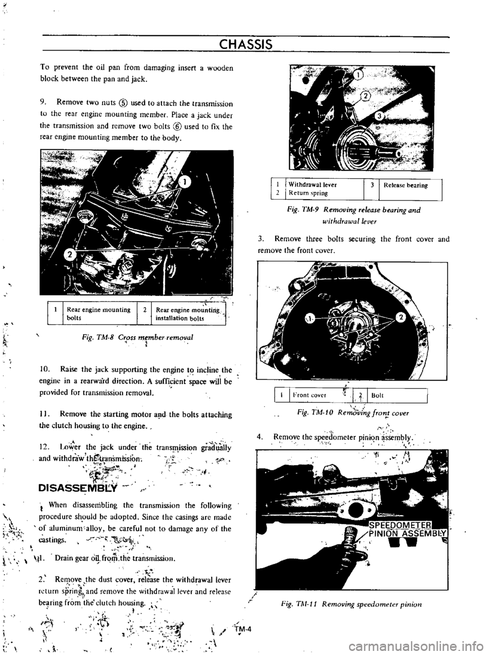
9
Remove
two
nuts
@
used
to
attach
the
transmission
to
the
rear
engine
mounting
member
Place
a
jack
under
the
transmission
and
remove
two
bolts
@
used
to
fix
the
rear
engine
mounting
member
to
the
body
It
I
Rear
engine
mou
ting
installation
bolts
I
Rear
engine
mounting
bolts
I
2
Fig
TM
8
C
oss
Fberremoval
10
Raise
the
jack
supporting
the
engine
to
incline
the
engine
in
a
rearward
direction
A
sufficient
space
will
be
provided
for
transmission
removal
I
Remove
the
starting
motor
a
d
the
bolts
attaching
the
clutch
housing
to
the
engine
12
Lower
the
jack
under
tlie
and
withdraw
thS
transmission
iJ
DISASSEMBI
Y
trans
fljssion
gradu3Ily
1
j
I
When
disassembling
the
transmission
the
following
procedure
sh
ould
pe
adopted
Since
the
casings
are
made
of
aluminum
alloy
be
careful
not
to
damage
any
of
the
castings
C
t
l
t1
Drain
gear
o
frqrP
the
transmission
I
2
Rc
ove
the
dust
cover
release
the
withdrawal
lever
n
turn
sprin
and
remove
the
withdrawal
lever
and
release
bC
lring
from
the
clutch
housing
h
IF
i
Iii
h
l
11
I
W
ithdrawallever
I
Return
spring
1
31
Release
bearing
Fig
TM
9
Removing
release
bearing
and
withdrawal
lever
3
Remove
three
bolts
securing
the
front
cover
and
remove
the
front
cover
II
I
Front
coveT
L
I
Bolt
Fig
TM
10
Remd
ving
fron
cover
4
Remove
the
spced
omcter
pinion
assembly
1f
SPEEDOMETER
PINION
ASSEMB
Y
w
Fig
TM
11
Removing
speedometer
pinion
TM
4
Page 496 of 513
TR
ANSMISSION
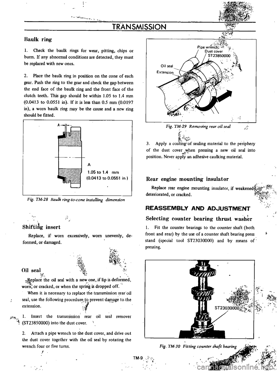
Baulk
ring
I
Check
the
baulk
rings
for
wear
pitting
chips
or
burrs
If
any
abnormal
conditions
are
detected
they
must
be
replaced
with
new
ones
2
Place
the
baulk
ring
in
position
on
the
cone
of
each
gear
Push
the
ring
to
the
gear
and
check
the
gap
between
the
end
face
of
the
bauIk
ring
and
the
front
face
of
the
clutch
teeth
This
gap
should
be
within
1
05
to
I
4
mm
0
0413
to
0
0551
in
If
it
is
less
than
0
5
mm
0
0197
in
a
worn
bauIk
ring
may
be
the
cause
and
a
new
ring
should
be
fitted
ii
V
ilillltII
l
A
1
05
to
1
4
mm
0
0413
to
0
0551
in
Fig
TM
28
ulk
ring
to
cone
installing
dimension
ShiftiAg
insert
Replace
if
worn
excessively
worn
unevenly
de
formed
or
damaged
Oil
seal
i
T
l
l
11
tT
Replace
the
oil
seal
with
a
new
one
if
lip
is
deformed
f
worn
or
cracked
or
when
the
spring
is
dropped
off
When
it
is
necessary
to
replace
the
transmission
rear
oil
seal
use
the
following
procedurecto
prevent
d
age
to
the
extension
l
1
Insert
the
transmission
rear
oil
seal
remover
ST23850000
into
the
dust
cover
2
Attach
a
pipe
wrench
to
the
dust
cover
and
drive
out
the
dust
cover
together
with
the
oil
seal
by
rotating
the
wrench
four
or
five
turns
I
Oil
seal
Extension
IJ
y
Fig
TM
29
Removing
rear
oil
seal
r
VI
1
3
Apply
a
coating
of
sealing
material
to
the
periphery
of
the
dust
cover
when
pressing
a
new
oil
seal
into
position
Never
apply
an
adhesive
caulking
material
Rear
engine
mounting
insulator
Replace
rear
engine
mounting
insulator
if
weakened
a
deteriorated
or
cracked
7i
1
rt
REASSEMBLY
AND
AD
JUSTMENT
Selecting
counter
bearing
thrust
washer
l
Fit
the
counter
bearings
to
the
counter
shaft
both
front
and
rear
by
the
use
of
a
counter
shaft
bearing
press
stand
special
tool
ST23030000
and
by
means
of
pressing
r
j
Itf
Fig
TM
JO
Fitting
counter
shaft
bearing
r
JJff
i
it
l
t
i
j
IlK
Ji
t
l
k
TM
9
Page 509 of 513
CHASSIS
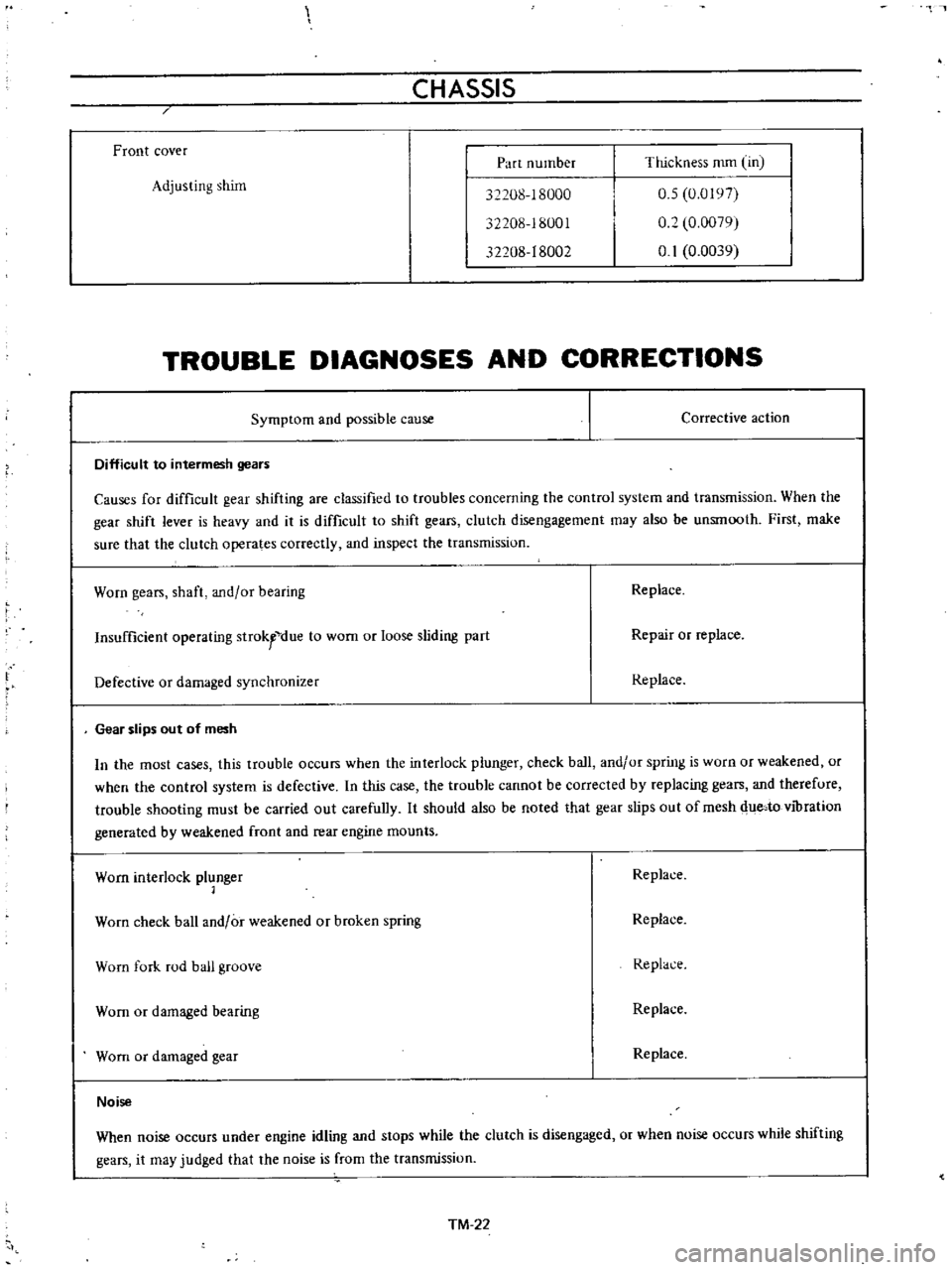
Front
cover
Part
number
Thickness
mm
Un
Adjusting
shim
32208
18000
32208
18001
32208
18002
0
5
0
0197
0
2
0
0079
0
1
0
0039
TROUBLE
DIAGNOSES
AND
CORRECTIONS
Symptom
and
possible
cause
Corrective
action
Difficult
to
intermesh
gears
Causes
for
difficult
gear
shifting
are
classified
to
troubles
concerning
the
control
system
and
transmission
When
the
gear
shift
lever
is
heavy
and
it
is
difficult
to
shift
gears
clutch
disengagement
may
also
be
unsmooth
First
make
sure
that
the
clutch
operates
correctly
and
inspect
the
transmission
Worn
gears
shaft
and
or
bearing
Replace
Insufficient
operating
strokfdue
to
wom
or
loose
sliding
part
Repair
or
replace
Defective
or
damaged
synchronizer
Replace
Gear
slips
out
of
mesh
In
the
most
cases
this
trouble
occurs
when
the
interlock
plunger
check
ball
and
or
spring
is
wuro
or
weakened
or
when
the
control
system
is
defective
In
this
case
the
trouble
cannot
be
corrected
by
replacing
gears
and
therefure
trouble
shooting
must
be
carried
out
carefully
It
should
also
be
noted
that
gear
slips
out
of
mesh
due
to
vibration
generated
by
weakened
front
and
rear
engine
mounts
Worn
interlock
plunger
1
Replace
Worn
check
ball
and
or
weakened
or
broken
spring
Replace
Worn
fork
rod
ball
groove
Replace
Worn
or
damaged
bearing
Replace
Worn
or
damaged
gear
Replace
Noise
When
noise
occurs
under
engine
idling
and
stops
while
the
clutch
is
disengaged
or
when
noise
occurs
while
shifting
gears
it
may
judged
that
the
noise
is
from
the
transmissiun
TM
22