1973 DATSUN B110 clutch
[x] Cancel search: clutchPage 426 of 513
ENGINE
CLEANING
AND
INSPECTION
Clean
all
disassembled
parts
Be
careful
not
to
use
grease
dissolving
solvent
for
cleaning
of
the
over
running
clutch
armature
assembly
magnetic
switch
assembly
and
field
coils
since
solvent
dissolves
grease
packed
in
the
clutch
mechanism
and
damages
the
coils
or
insulators
Check
them
for
damage
or
excessive
wear
Replace
them
as
required
Terminal
Check
the
terminal
for
damage
and
wear
and
replace
if
necessary
Field
coil
Check
the
field
coil
for
insulation
If
the
coil
insulator
is
damaged
or
worn
replace
Testing
field
coil
for
continuity
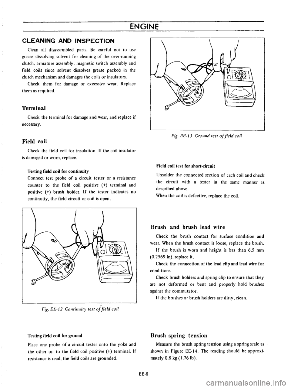
Connect
test
probe
of
a
circuit
tester
or
a
resistance
counter
to
the
field
coil
positive
terminal
and
positive
brush
holder
If
the
tester
indicates
no
continuity
the
field
circuit
or
coil
is
open
O
Fig
EE
12
Cotltinuity
test
of
field
coil
Testing
field
coil
for
ground
Place
one
probe
of
a
circuit
tester
onto
the
yoke
and
the
othef
on
to
the
field
coil
positive
tenninal
If
resistance
is
read
the
field
coils
are
grounded
ol
I
Fig
EE
13
CTound
test
of
field
coil
Field
coil
test
for
short
ircuit
Un
solder
the
connected
section
of
each
coil
and
check
the
circuit
with
a
tester
in
the
same
manner
as
described
above
When
the
coil
is
defective
replace
the
coil
Brush
and
brush
lead
wire
Check
the
brush
contact
for
surface
condition
and
wear
When
the
brush
contact
is
loose
replace
the
brush
If
the
brush
is
worn
and
height
is
less
than
6
5
rom
0
2569
in
replace
it
Check
the
connection
of
the
lead
clip
and
lead
wire
for
conditions
Check
brush
holders
and
spring
clip
to
ensure
that
they
are
not
deformed
or
bent
and
properly
hold
brushes
against
the
commutator
If
the
brushes
Of
brush
holders
are
dirty
clean
Brush
spring
tension
Measure
the
brush
spring
tension
using
a
spring
scale
as
shown
in
Figure
EE
14
The
reading
should
be
approxi
mately
0
8
kg
I
76
Ib
EE
6
Page 428 of 513
ENGINE
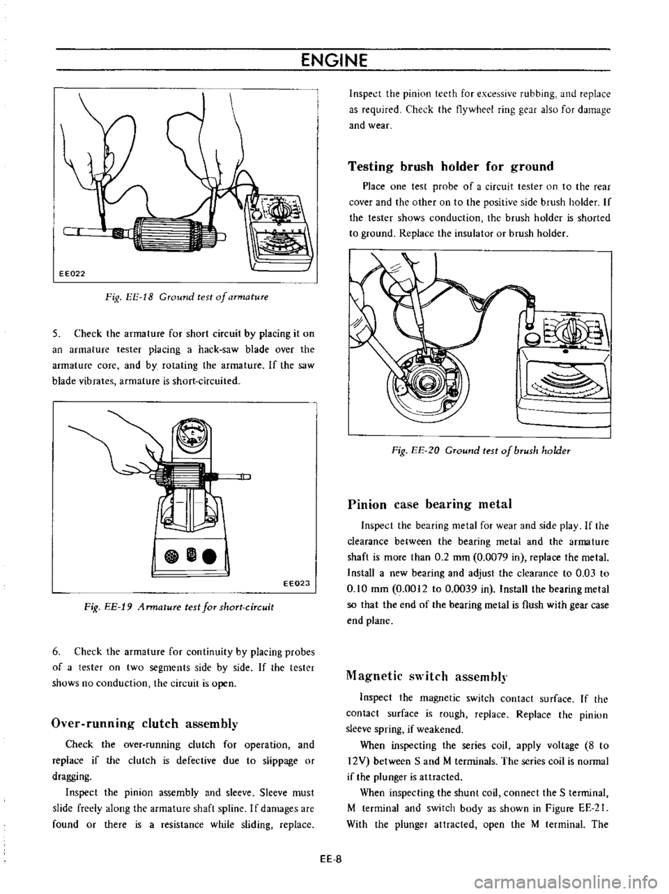
EE022
Fig
EE
18
Ground
test
of
armature
5
Check
the
armature
for
short
circuit
by
placing
it
on
an
armature
tester
placing
a
hack
saw
blade
over
the
armature
core
and
by
rotating
the
armature
If
the
saw
blade
vibrates
armature
is
short
circuited
EE023
Fig
EE
19
4
rmature
test
for
short
circuit
6
Check
the
armature
for
continuity
by
placing
probes
of
a
tester
on
two
segments
side
by
side
If
the
tester
shows
no
conduction
the
circuit
is
open
Over
runnmg
clutch
assembly
Check
the
over
running
clutch
for
operation
and
replace
if
the
clutch
is
defective
due
to
slippage
or
dragging
Inspect
the
pinion
assembly
and
sleeve
Slceve
must
slide
freely
along
the
armature
shaft
spline
I
f
damages
are
found
or
there
is
a
resistance
while
sliding
replace
Inspect
the
pinion
teeth
for
excessive
rubbing
and
replace
as
required
Check
the
flywheel
ring
gear
also
for
damage
and
wear
Testing
brush
holder
for
ground
Place
one
test
probe
of
a
circuit
tester
on
to
the
rear
cover
and
the
other
on
to
the
positive
side
brush
holder
If
the
tester
shows
conduction
the
brush
holdcr
is
shorted
to
ground
Replace
the
insulator
or
brush
holder
od
l
Fig
EE
20
GTound
test
of
bTush
holder
Pinion
case
bearing
metal
Inspect
the
bearing
metal
for
wear
and
sidc
play
If
the
clearance
between
the
bearing
metal
and
the
arma
ture
shaft
is
mOTe
than
0
2
mm
0
0079
in
replace
the
metal
Install
a
new
bearing
and
adjust
the
clearance
to
0
03
to
0
10
mm
0
0012
to
0
0039
in
Install
the
bearing
metal
so
that
the
end
of
the
bearing
metal
is
flush
with
gear
case
end
plane
Magnetic
switch
assembly
Inspect
the
magnetic
switch
contact
surface
If
the
contact
surface
is
rough
replace
Replace
the
pinion
sleeve
spring
if
weakened
When
inspecting
the
series
coil
apply
voltagc
8
to
12V
between
Sand
M
terminals
The
series
coil
is
normal
if
the
plunger
is
attracted
When
inspecting
the
shunt
coil
connect
the
S
terminal
M
terminal
and
switch
body
as
shown
in
Figure
EE
21
With
the
plunger
attracted
open
the
M
terminal
The
EE
S
Page 434 of 513

Pinion
intermeshes
with
ring
gear
Starting
motor
rotates
and
pinion
intermeshes
with
ring
gear
but
ro
tation
is
too
slow
When
starting
switch
is
set
to
OFF
the
start
ing
motor
does
not
stop
Starting
motor
Battery
Wiring
Ignition
switch
Starting
motor
Ignition
switch
Magnetic
switch
Starting
motor
ENGINE
Faulty
pinion
sliding
Dropped
off
lever
pin
Excessive
plunger
L
dimension
Defective
over
running
clutch
Over
discharging
Improper
or
loose
terminal
contact
Improperly
tightened
connection
Rough
contact
surface
Shorted
armature
coil
or
field
coil
Worn
brush
or
insufficient
spring
pressure
Contaminated
commutator
or
im
proper
brush
contact
Defective
mica
Lack
of
metal
lubrication
Armature
contacted
with
pole
core
Faulty
returning
Seized
contact
Shorted
coil
Faulty
plunger
sliding
Pinion
does
not
disengage
from
the
ring
gear
smoothly
Pinion
spline
does
not
disengage
smoothly
Seized
pinion
metal
EE
14
Repair
Repair
Adjust
Replace
Charge
battery
Repair
and
retighten
Retighten
Repair
or
replace
Repair
or
replace
Repair
or
replace
Repair
Repair
Repair
or
replace
Repair
or
replace
Replace
Replace
Replace
Replace
Repair
or
replace
Repair
or
replace
Replace
Page 468 of 513
ENGINE
REMOVAL
INSTAllATION
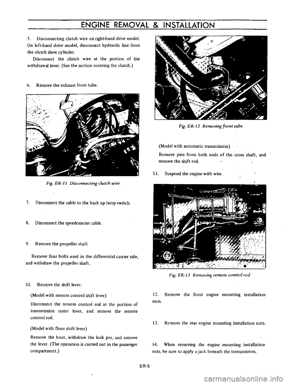
5
Disconnecting
clutch
wire
on
right
hand
drive
model
On
left
hand
drive
model
disconnect
hydraulic
line
from
the
clutch
slave
cylinder
Disconnect
the
clutch
wire
at
the
portion
of
the
withdrawal
lever
See
the
section
covering
the
clutch
6
Remove
the
exhaust
front
tube
ij
f
I
Fig
ER
11
Disconnecting
dutch
wire
7
Disconnect
the
cable
to
the
back
up
lamp
switch
8
Disconnect
the
speedometer
cable
9
Remove
the
propeller
shaft
Remove
four
bolts
used
in
the
differential
carrier
side
and
withdraw
the
propeller
shaft
10
Remove
the
shift
lever
Model
with
remote
control
shift
lever
Disconnect
the
remote
control
rod
at
the
portion
of
transmission
outer
lever
and
remove
the
remote
control
rod
Model
with
floor
shift
lever
Remove
the
boot
withdraw
the
lock
pin
and
remove
the
lever
The
operation
is
carried
out
in
the
passenger
compartment
Fig
ER
12
Removing
fTont
tube
Model
with
automatic
transmission
Remove
pins
from
both
ends
of
the
cross
shaft
and
remove
the
shift
rod
II
Suspend
the
engine
with
wire
Fig
ER
13
Removing
remote
control
rod
12
Remove
the
front
engine
mounting
installation
nuts
13
Remove
the
rear
engine
mounting
installation
nuts
14
When
removing
the
engine
mounting
installation
nuts
be
sure
to
apply
a
jack
beneath
the
transmission
ER
5
Page 470 of 513
DATSUN
1200
MODEL
B
110
SERIES
I
NISSAN
I
NISSAN
MOTOR
CO
LTD
TOKYO
JAPAN
SECTION
CL
CLUTCH
CLUTCH
CLUTCH
CONTROL
SfRVICE
DATA
AND
SPECIFICATIONS
TROUBLE
DIAGNOSES
AND
CORRECTIONS
CL
1
CL
5
CL
12
CL
13
Page 471 of 513
CLUTCH
CLUTCH
CONTENTS
DESCRIPTION
REMOVAL
DISASSEMBL
Y
INSPECTION
AND
ADJUSTMENT
Clutch
assembly
Cll
CL
2
CL
2
CL
2
CL
2
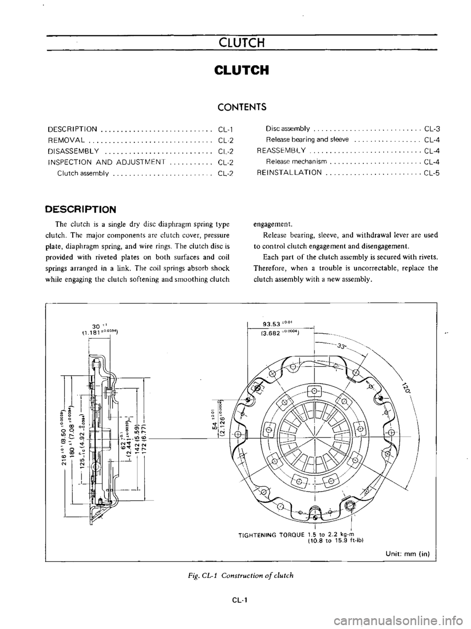
DESCRIPTION
The
clutch
is
a
single
dty
disc
diaphragm
spring
type
clutch
The
major
components
are
clutch
cover
pressure
plate
diaphragm
spring
and
wire
rings
The
clutch
disc
is
provided
with
riveted
pia
tes
on
both
surfaces
and
coil
springs
arranged
in
a
link
The
coil
springs
absorb
shock
while
engaging
the
clutch
softening
and
smoothing
clutch
30
1181
I
4J
I
m
I
I
5
O
N
l
l
9
p
1L
oz
l
t
O
Ii
N
lt
o
O
Vf
I
1
I
t
I
0
tN
00
f
M
g
1
co
0
00
U
N
N
y
Disc
assembly
Release
bearing
and
sleeve
REASSEMBL
Y
CL
3
CL
4
CL
4
CL
4
CL
5
Release
mechanism
REINSTALLATION
engagement
Release
bearing
sleeve
and
withdrawal
lever
are
used
to
control
clutch
engagement
and
disengagement
Each
part
of
the
clutch
assembly
is
secured
with
rivets
Therefore
when
a
trouble
is
uncorrectable
replace
the
clutch
assembly
wHh
J
new
assembly
93
53
3
682
JOOD4
33
Unit
mm
in
Fig
CL
l
Construction
of
clutch
ell
Page 472 of 513
CHASSIS
REMOVAL
The
clutch
assembly
is
dismounted
primarily
in
the
same
manner
as
the
engine
assembly
Thus
when
dis
mounting
the
clutch
assembly
refer
to
the
Section
TM
Transmission
Removal
and
other
relative
sections
W
II
11
I
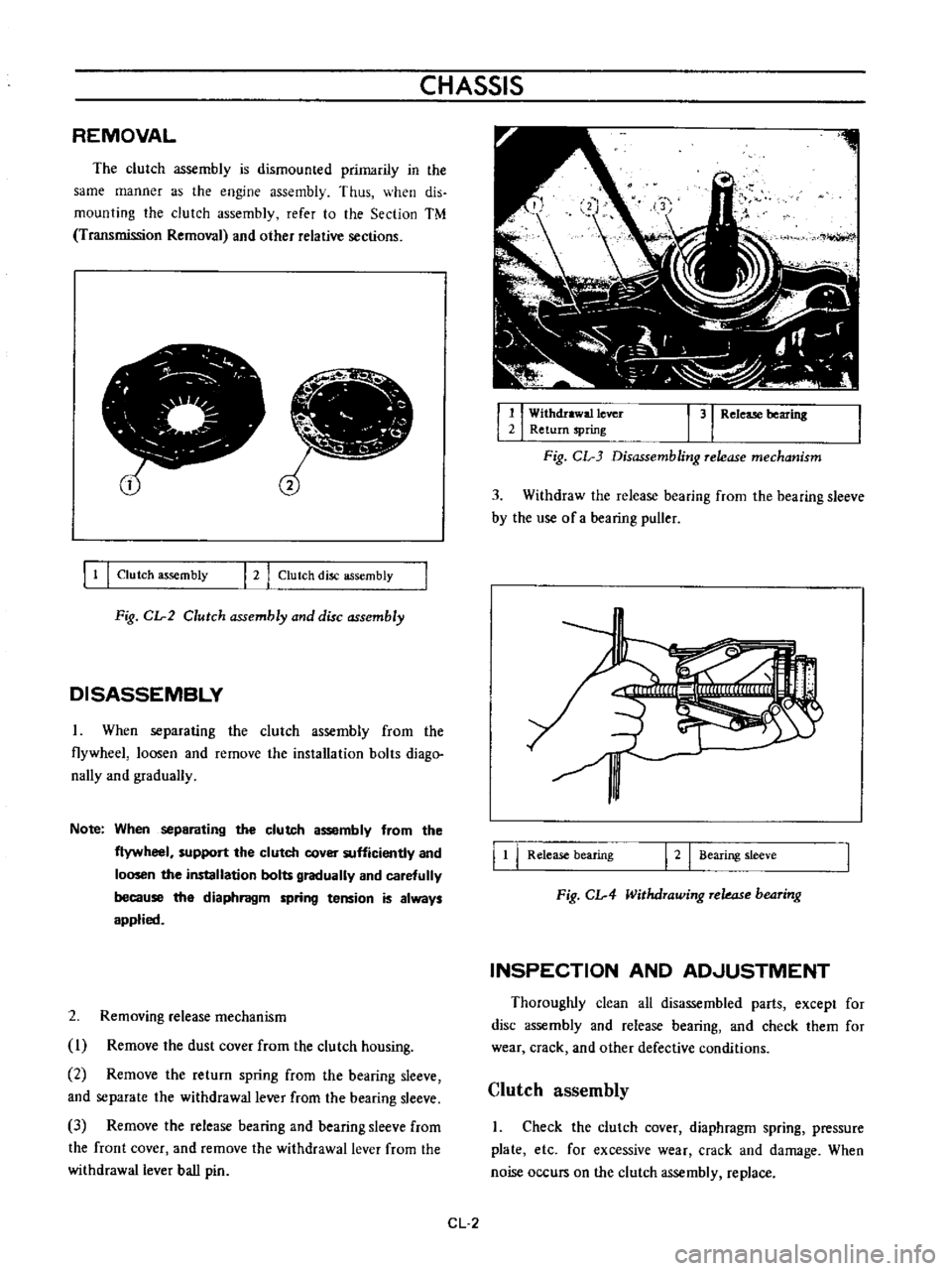
Clutch
assembly
I
2
I
Clutch
disc
assembly
Fig
CIr2
Clutch
assembly
and
disc
assembly
DISASSEMBLY
When
separating
the
clutch
assembly
from
the
flywheel
loosen
and
remove
the
installation
bolts
diago
nally
and
gradually
Note
When
separating
the
clutch
assembly
from
the
flywheel
support
the
clutch
cover
sufficiently
and
loosen
the
installation
bolts
gradually
and
carefully
because
the
diaphragm
spring
tension
is
always
applied
2
Removing
release
mechanism
I
Remove
the
dust
cover
from
the
clutch
housing
2
Remove
the
return
spring
from
the
bearing
sleeve
and
separate
the
withdrawal
lever
from
the
bearing
sleeve
3
Remove
the
release
bearing
and
bearing
sleeve
from
the
front
cover
and
remove
the
withdrawal
lever
from
the
withdrawal
lever
ball
pin
1
I
Withdrawal
lever
3
Release
bearing
2
Return
spring
Fig
CL
3
Disassembling
release
mechanism
3
Withdraw
the
release
bearing
from
the
bearing
sleeve
by
the
use
of
a
bearing
puller
I
t
I
Release
bearing
I
2
I
Bearing
sleeve
Fig
CIr4
Withdrawing
rekas
b04ring
INSPECTION
AND
ADJUSTMENT
Thoroughly
clean
all
disassembled
parts
except
for
disc
assembly
and
release
bearing
and
check
them
for
wear
crack
and
other
defective
conditions
Clutch
assembly
I
Check
the
clutch
cover
diaphragm
spring
pressure
plate
etc
for
excessive
wear
crack
and
damage
When
noise
occurs
on
the
clutch
assembly
replace
CL
2
Page 473 of 513
CLUTCH
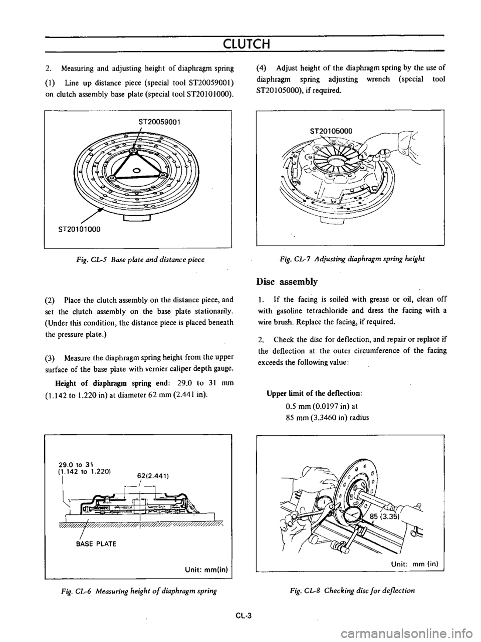
2
Measuring
and
adjusting
height
of
diaphragm
spring
I
Line
up
distance
piece
special
tool
ST20059001
on
clutch
assembly
base
plate
special
tool
ST20101O
0
ST20059001
I
ST20101000
Fig
CL
5
Base
plate
and
distance
piece
2
Place
the
clutch
assembly
on
the
distance
piece
and
set
the
clutch
assembly
on
the
base
plate
stationarily
Under
this
condition
the
distance
piece
is
placed
beneath
the
pressure
plate
3
Measure
the
diaphragm
spring
height
from
the
upper
surface
of
the
base
plate
with
vernier
caliper
depth
gauge
Height
of
diaphragm
spring
end
29
0
to
31
mm
1
142
to
1
220
in
at
diameter
62
mm
2
441
in
29
0
to
31
It
142
to
1
2201
6212
44
t
r
1
G
L
ir
I
LJIlW
I
y
y
x
l
i
0
BASE
PLATE
Unit
mm
in
Fig
CL
6
Measuring
height
of
dio
phTagm
spTing
4
Adjust
height
of
the
diaphragm
spring
by
the
use
of
diaphragm
spring
adjusting
wrench
special
tool
ST20
1
05000
if
required
Fig
CL
7
Adjusting
dio
phTagm
spring
height
Disc
assembly
If
the
facing
is
soiled
with
grease
or
oil
clean
off
with
gasoline
tetracWoride
and
dress
the
facing
with
a
wire
brush
Replace
the
facing
if
required
2
Check
the
disc
for
deflection
and
repair
or
replace
if
the
deflection
at
the
outer
circumference
of
the
facing
exceeds
the
following
value
Upper
limit
of
the
deflection
0
5
mm
0
0197
in
at
85
mm
3
3460
in
radius
Unit
mm
in
Fig
CL
8
Checking
disc
fOT
deflection
CL
3