Page 65 of 513
AUTOMATIC
TRANSMISSION
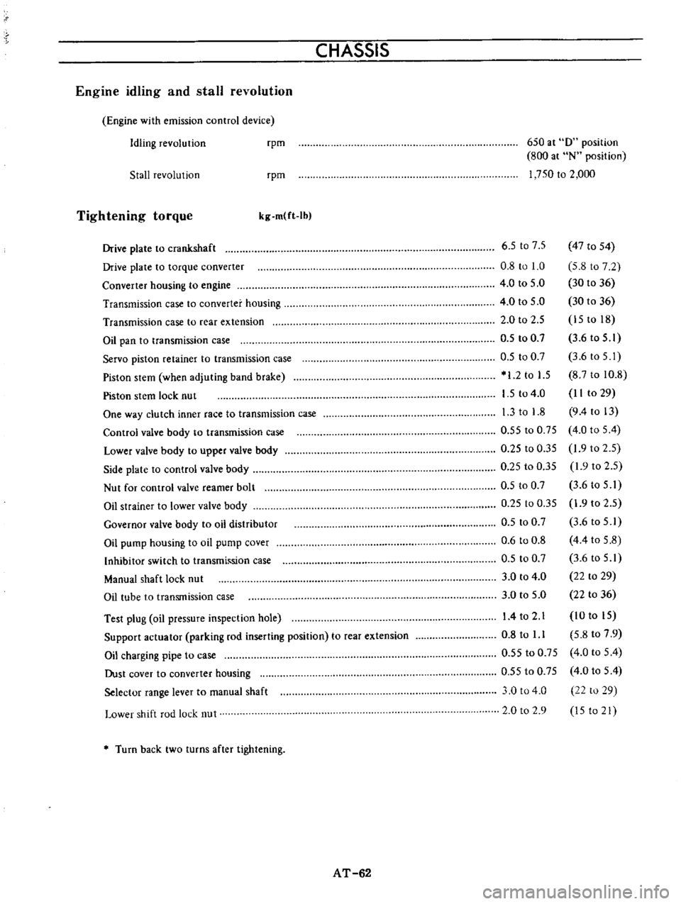
Specifications
and
adjustment
Automatic
transmission
assembly
Model
code
number
Torque
converter
assembly
Stamped
mark
on
the
TIC
Front
clu
tch
Number
of
drive
plate
Number
of
driven
plates
Clearance
Thickness
of
retaining
plate
Rear
clutch
Number
of
drive
plates
Number
of
driven
plate
Clearance
Thickness
of
retaining
plate
Low
reverse
brake
Number
of
drive
plates
Number
of
driven
plates
Clearance
Thickness
of
retaining
plate
Brake
band
Piston
size
Big
dia
Small
dia
Control
valve
assembly
Stamped
mark
on
trainer
Governor
assembly
Stamped
mark
on
governor
body
mm
in
mm
in
mm
in
mm
in
mm
in
mm
in
mm
in
AT
61
x
0100
IO
C
3
3
1
6
to
1
8
0
0630
to
0
071
10
6
0
417
10
8
0
425
11
0
0
433
11
2
0
441
II
4
0
449
11
6
0
457
3
3
1
0
to
1
5
0
039
to
0
059
8
35
0
3287
3
3
0
80
to
1
05
0
0315
to
0
0413
15
8
0
622
16
0
0
630
16
2
0
638
16
4
0
646
16
6
0
654
16
8
0
661
64
2
520
44
I
732
E
35
Page 66 of 513

CHASSIS
Engine
idling
and
stall
revolution
Engine
with
emission
control
device
Idling
revolution
rpm
650
at
0
position
800
at
N
position
1
750
to
2
000
Stall
revolution
rpm
Tightening
torque
kg
m
ft
Ib
Test
plug
oil
pressure
inspection
hole
Support
actuator
parking
rod
inserting
position
to
rear
extension
Oil
charging
pipe
to
case
Dust
cover
to
converter
housing
Selector
range
lever
to
manual
shaft
Lower
shift
rod
lock
nut
6
5
t07
5
47
to
54
0
8
to
1
0
5
8
to
7
2
4
0
to
5
0
30
to
36
4
0
to
5
0
30
to
36
2
0
to
2
5
15
to
18
0
5
to
0
7
3
6
to
5
1
0
5
to
0
7
3
6toS
I
1
2
to
1
5
8
7
to
10
8
1
5
to
4
0
II
to
29
1
3
to
1
8
9
4
to
13
0
55
to
0
75
4
0
to
5
4
0
25
to
0
35
1
9
to
2
5
0
25
to
0
35
1
9
to
2
5
0
5
to
0
7
3
6
to
5
I
0
25
to
0
35
1
9
to
2
5
0
5
to
0
7
3
6
to
5
1
0
6
to
0
8
4
4
to
5
8
0
5
to
0
7
3
6
to
5
1
3
0
to
4
0
22
to
29
3
0
to
5
0
22
to
36
14
to
2
1
10
to
15
0
8
to
l
l
5
8
to
7
9
0
55
to
0
75
4
0
to
5
4
0
55
to
0
75
4
0
to
5
4
3
0
to
4
0
22
to
29
2
0
to
2
9
15
to
21
Drive
plate
to
crankshaft
Drive
plate
to
torque
converter
Converter
housing
to
engine
Transmission
case
to
converter
housing
Transmission
case
to
rear
extension
Oil
pan
to
transmission
case
Servo
piston
retainer
to
transmission
case
Piston
stem
when
adjuting
band
brake
Piston
stem
lock
nut
One
way
clutch
inner
race
to
transmission
case
Control
valve
body
to
transmission
case
Lower
valve
body
to
upper
valve
body
Side
plate
to
control
valve
body
Nut
for
control
valve
reamer
bolt
Oil
strainer
to
lower
valve
body
Governor
valve
body
to
oil
distributor
Oil
pump
housing
to
oil
pump
cover
Inhibitor
switch
to
transmh
sion
case
Manual
shaft
lock
nut
Oil
tube
to
transmission
case
Turn
back
two
turns
after
tightening
AT
62
Page 84 of 513

PROPELLER
SHAFT
DIFFERENTIAL
CARRIER
Incorrect
adjustment
of
bearings
or
gears
Severe
service
due
to
an
excessive
loading
improper
use
of
clutch
Loosened
bolts
and
nuts
such
as
ring
gear
clamp
bolts
Oil
leakage
Worn
out
damaged
or
improperly
driven
front
oil
seal
or
bruised
dented
or
abnormally
worn
slide
face
of
companion
flange
Loosened
bolts
holding
gear
carrier
Defective
gasket
Loosen
filler
or
drain
plug
Clogged
or
damaged
breather
SERVICE
DATA
AND
SPECIFICATIONS
Type
of
differential
gear
carrier
assembly
Final
gear
type
Final
gear
ratio
number
of
teeth
Sedan
Coupe
Van
Drive
pinion
Preload
with
oil
seal
Preload
without
oil
seal
Thickness
of
drive
pinion
adjusting
shims
kg
cm
in
lb
kg
cm
in
lb
mm
in
Pinion
bearing
adjusting
spacer
Ring
gear
Backlash
between
ring
gear
and
pinion
Run
out
of
rear
side
of
ring
gear
mm
in
mm
in
Side
gear
and
pinion
mate
Thickness
of
side
gear
thrust
washers
mm
in
PD
17
Replace
defective
parts
Replace
defective
parts
Replace
defective
parts
Replace
the
defective
oil
seal
Ammend
the
affected
flange
with
sand
paper
or
replace
if
necessary
Tighten
the
bolts
to
specified
torque
Replace
defective
parts
with
new
ones
Tighten
the
plug
Repair
or
replace
H145A
Hypoid
3
900
39
10
7
to
9
6
1
to
7
8
6
to
8
5
2
to
6
9
From
2
74
to
3
25
0
1079
to
0
1280
Spacing
0
Q3
0
0012
Non
adjustable
collapsible
spacer
0
10
to
0
15
0
0039
to
0
0059
Less
than
0
05
0
0020
0
76
to
0
91
0
0299
to
0
0358
Page 276 of 513
Tool
number
Tool
name
STl9
I
50000
Anti
dieseling
solenoid
spanner
Clutch
tool
ST20610000
Clutch
aligning
bar
ST20101000
Clutch
assembly
base
plate
ST20059001
Clu
tch
assembly
distance
piece
SERVICE
EQUI
PMENT
Figure
mm
inch
12
10
4721
0
o
8
C
307
l
j
@@
SE
4
Description
For
installing
the
anti
dieseling
solenoid
spanner
For
centering
the
clutch
disc
For
measuring
the
diaphragm
spring
height
Use
with
the
distance
piece
For
measuring
the
diaphragm
spring
height
Use
with
the
base
plate
S
M
reference
page
See
Fig
No
Page
EF
12
Page
ET
9
Fig
CL
14
Fig
CL
5
Fig
CL
5
Page 279 of 513
SERVICE
EQUIPMENT
Automatic
transmission
tool
Tool
number
S
M
reference
Tool
name
Figure
Description
page
See
mm
inch
Fig
No
ST25050001
Oil
pressure
gauge
Use
for
checking
hydraulic
Fig
AT
112
set
Y
pressure
SE119
ST07870000
Transmission
case
Use
for
setting
transmission
Page
AT
37
stand
SE120
ST25850000
Sliding
hammers
Use
for
removing
oil
pump
Fig
AT
56
r
SE121
ST25420001
ST2542000
Clutch
spring
compressor
Use
for
assembling
or
disassem
bling
front
and
rear
clutch
Fig
AT
79
Fig
AT
86
SE122
sE
7
Page 280 of 513
SERVICE
EQUIPMENT
Tool
number
S
M
reference
Tool
name
Figure
Description
page
See
Fig
No
GG930
10000
Torque
wrench
Use
for
tightening
correct
torque
Fig
A
T
69
Max
torque
4
6
kg
m
0
33
ft
lb
Drive
angle
3
8
square
SE123
ST255
12001
Socket
extension
Socket
extension
to
connect
Fig
A
T
69
0
torque
wrench
GG930
I
000
with
1
2
square
socket
wrench
SE124
ST25
160000
Torque
driver
Use
for
tightening
correct
Fig
AT
107
torque
Max
torque
1
04
kg
m
Fig
AT
108
u
90
ft
Ib
SE125
HT69860000
Snap
ring
Use
for
removing
and
replacing
Fig
AT
59
remover
snap
ring
SE126
ST25320001
Snap
ring
Use
for
removing
and
replacing
Fig
AT
79
snap
ring
remover
Go
O
SE127
ST25570000
Hex
head
Use
for
removing
and
installing
Fig
AT
64
extension
one
way
clutch
inner
race
with
Fig
AT
69
torque
wrench
Drive
angle
1
2
square
and
6
mm
across
flat
SE128
width
sE
8
Page 302 of 513
GENERAL
INFORMATION
RECOMMENDED
LUBRICANT
SPECI
FICATIONS
Item
Gasoline
engine
oil
o
Transmission
and
steering
Differential
Automatic
TIM
fluid
Multipurpose
grease
Brake
and
clutch
fluid
Antifreeze
coolant
i
Specifications
SAE
Classification
SO
or
SE
API
G
L
4
API
GL
5
Type
DEXRON
NLGI2
DOT
3
Long
Life
Coolant
GI
6
Remarks
Furthermore
refer
to
SAE
recommended
viscosity
table
See
Page
GI
5
Lithium
soap
base
Page 324 of 513

EMISSION
CONTROL
AND
TUNE
UP
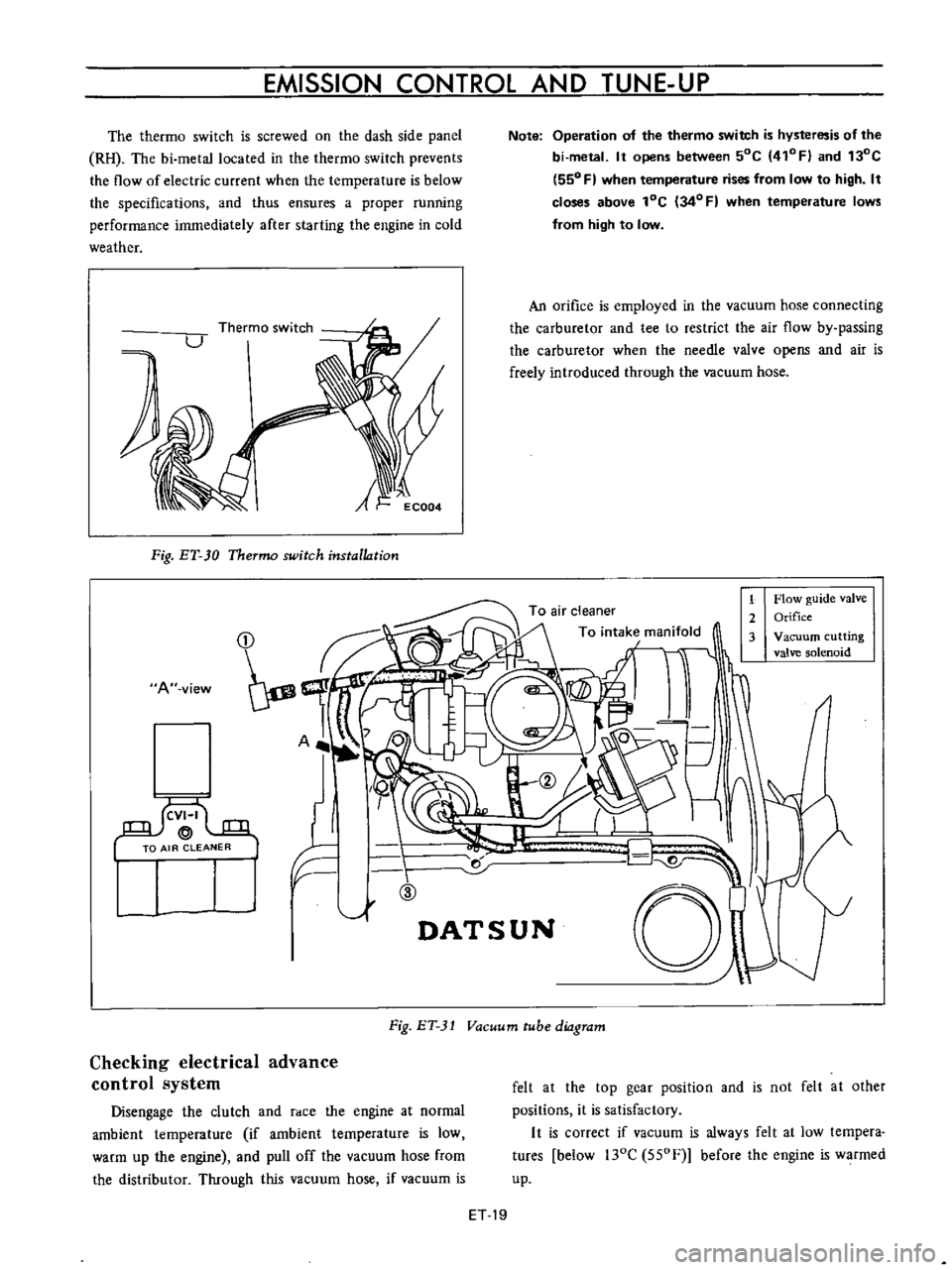
The
thermo
switch
is
screwed
on
the
dash
side
panel
RH
The
bi
metallocated
in
the
thermo
switch
prevents
the
flow
of
electric
current
when
the
temperature
is
below
the
specifications
and
thus
ensures
a
proper
running
performance
immediately
after
starting
the
engine
in
cold
weather
A
Fig
ET
30
Thermo
switch
installation
A
view
I
llf
F
ID
1
Note
Operation
of
the
thermo
switch
is
hysteresis
of
the
bi
metal
It
opens
between
50C
410FI
and
130C
550
F
when
temperature
rises
from
low
to
high
It
closes
above
lOC
34
0
F
when
temperature
lows
from
high
to
low
An
orifice
is
employed
in
the
vacuum
hose
connecting
the
carburetor
and
tee
to
restrict
the
air
flow
by
passing
the
carburetor
when
the
needle
valve
opens
and
air
is
freely
introduced
through
the
vacuum
hose
1
Flow
guide
valve
2
Orifice
3
Vacuum
cutting
valve
solenoid
r
d
01
DATSUN
Fig
ET
31
Vacuum
tube
diagram
Checking
electrical
advance
control
system
Disengage
the
clutch
and
race
the
engine
at
normal
ambient
temperature
if
ambient
temperature
is
low
warm
up
the
engine
and
pull
off
the
vacuum
hose
from
the
distributor
Through
this
vacuum
hose
if
vacuum
is
felt
at
the
top
gear
position
and
is
not
felt
at
other
positions
it
is
satisfactory
It
is
correct
if
vacuum
is
always
felt
at
low
tempera
tures
below
l30C
550F
before
the
engine
is
warmed
up
ET
19