1973 DATSUN B110 clutch
[x] Cancel search: clutchPage 28 of 513
I
CHASSIS
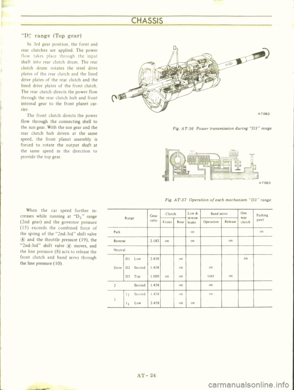
D
range
Top
gear
In
Jrd
gear
position
the
fornt
and
rear
dutches
are
applied
The
power
flow
takes
place
through
the
input
shaft
into
rear
dutch
drum
The
rear
clutch
drum
rotates
the
steel
drive
plates
of
the
rear
dutch
and
the
lined
drive
plates
of
the
rear
dutch
and
the
lined
drive
plates
of
the
fronl
clutch
The
rear
clutch
directs
the
power
flow
through
the
rear
clutch
hub
and
frunt
internal
gear
to
the
front
planet
car
rier
The
front
clutch
directs
the
power
now
through
the
connecting
sheU
to
the
sun
gear
With
the
sun
gear
and
the
rear
clutch
hub
driven
at
the
same
speed
the
front
planet
assembly
is
forced
to
rotate
the
output
shaft
at
the
same
speed
in
the
direction
to
provide
the
top
gear
When
the
car
speed
further
in
creases
while
running
at
02
range
2nd
gear
and
the
governor
pressore
I5
exceeds
the
combined
force
of
the
spring
of
the
2nd
3rd
shift
valve
@
and
the
throttle
pressure
19
the
2nd
3rd
shift
valve
@
moves
and
the
line
pressure
8
acts
to
release
the
front
clutch
and
band
servo
through
the
line
pressure
10
Fig
A
T
36
Power
transmission
during
D3
range
AT083
Fig
A
T
37
Operation
of
each
mechanism
D3
range
Clutch
Low
Band
servo
On
Parking
Range
c
w
ratio
Front
Rear
brake
Operalion
Release
c1ulCh
pawl
Park
00
on
Reverse
2
182
on
on
on
Ntulral
DI
low
2
458
on
on
Drive
D2
Second
1
458
on
on
OJ
Top
000
on
on
on
on
2
Second
1
458
on
on
12
Second
1
458
on
on
I
II
low
2
458
on
on
AT
24
Page 30 of 513
CHASSIS
1
range
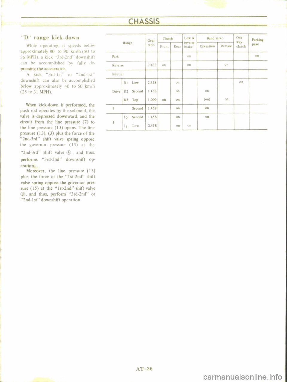
kick
down
lli1e
llperJling
JI
speeds
ht
Ii1
approximately
8U
to
90
km
h
50
to
56
i
1PII
J
kid
3rJ
2nJ
d0wnslllft
an
he
1
clllllplish
d
hy
fully
de
pressing
the
accelerator
A
kick
3rd
lsl
Of
nd
lst
downshift
can
also
be
accomplished
below
approximately
40
10
50
km
h
25
to
31
MPIl
When
kick
down
is
performed
the
push
rod
operates
by
the
solenoid
the
valve
is
depressed
downward
and
the
circuit
from
the
line
pressure
7
to
the
line
pressure
13
opens
The
line
pressure
IJ
3
plus
the
force
of
the
2nd
Jrd
shift
valve
spring
oppose
the
governor
pressure
15
at
the
2nd
Jrd
shift
valve
4
and
thus
performs
Jrd
2nd
downshift
op
eration
Moreover
the
line
pressure
13
plus
the
force
of
the
I
st
2nd
shift
valve
spring
oppose
the
governor
pres
sure
15
at
the
I
st
2nd
shift
valve
@
and
thus
perform
Jrd
2nd
or
2nd
I
downshift
operation
Clutch
Ln
l
BJ
nd
Cr
o
o
On
Park
ing
Ge
Range
reverse
way
pawl
rat
Fronl
Real
brake
Operalion
R
lea
c1ulch
Park
on
on
Re
erse
2182
n
on
on
Neulral
01
low
2
458
on
on
Orive
Dl
Second
1
458
on
on
OJ
Top
1
000
on
on
Ion
on
1
Second
1
458
on
on
tl
Second
1
458
on
on
t
low
2
458
on
on
AT
26
Page 31 of 513
AUTOMATIC
TRANSMISSION
I
ran
e
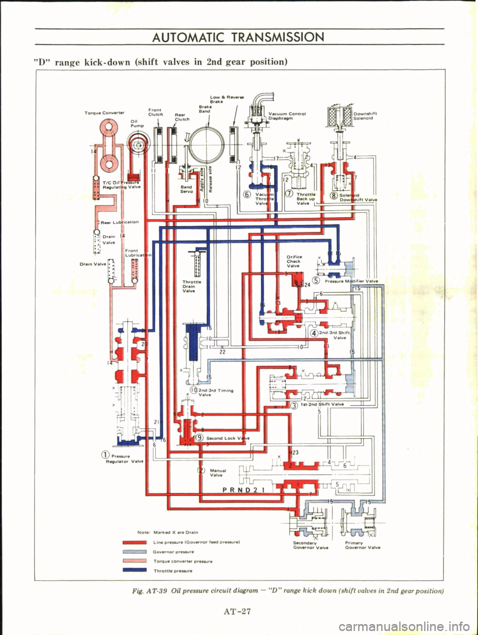
kick
down
shift
valves
in
2nd
gear
position
iQ
Front
ClutCh
L
llIR
B
ilk
8
e
Downshift
Solenoid
Torqu
Con
t
Q
I
Throttle
Back
up
V
lv
II
iftY
h
TIC
0
A
lV
A
Lubl
tion
e
S
lO
lID
VK
Th
o
I
V
v
8
Sol
Dow
Dr
I
V
I
F
lt
Lubrice
D
Yo
t
Otific
Check
0
Throttle
Dr
n
V
mm
OJ
12
Q
ht
2rod
hif
v
S
C
Ptenu
R
ul
to
Vel
8
Menu
0
PRND2
I
L
J
Jl
No
Me
klld
er
D
in
SKond
Prim
GO
no
0
1
Go
no
V
LIne
pr
s
100
0
l
d
p
1
Goy
rno
p
eslU
s
Torque
con
er
r
pr
Th
oUl
prnsu
Fig
A
T
39
Oil
pressure
circuit
diagram
D
range
kick
down
shift
valves
in
2nd
gear
position
AT
27
Page 32 of 513
CHASSIS
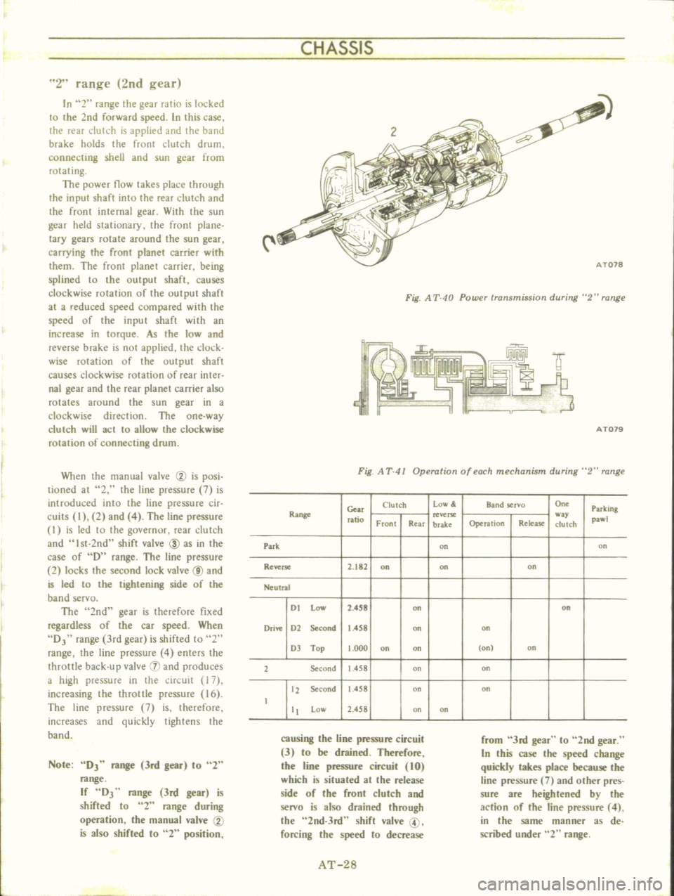
2
range
2nd
gear
In
2
range
the
gear
ratio
is
locked
to
the
2nd
forward
speed
In
this
case
the
rear
clutch
is
applied
and
the
band
brake
holds
the
front
clutch
drum
connecting
shell
and
sun
gear
from
rotating
The
power
flow
takes
place
through
the
input
shaft
into
the
rear
clutch
and
the
front
internal
gear
With
the
sun
gear
held
stationary
the
front
plane
lacy
gears
rotate
around
the
sun
gear
carrying
the
front
planet
carrier
with
them
The
front
planet
carrier
being
splined
to
the
output
shaft
causes
clockwise
rotation
of
the
output
shaft
at
a
reduced
speed
compared
with
the
speed
of
the
input
shaft
with
an
increase
in
torque
As
the
low
and
reverse
brake
is
not
applied
the
clock
wise
mlation
of
the
output
shaft
causes
clockwise
rotation
of
rear
inter
nal
gear
and
the
rear
planet
carrier
also
rotates
around
the
sun
gear
in
a
clockwise
direction
The
one
way
c1urch
will
act
to
allow
the
clockwise
rotation
of
connecting
drum
When
the
manual
valve
CV
is
posi
tioned
at
2
the
line
pressure
7
is
introduced
into
the
line
pressure
cir
cuits
I
2
and
4
The
line
pressure
I
is
led
to
the
governur
rear
dutch
and
Ist
2nd
shift
valve
ID
as
in
the
case
of
D
range
The
line
pressure
2
locks
the
second
lock
valve
@
and
is
led
to
the
tightening
side
of
the
band
servo
The
2nd
gear
is
therefore
fixed
regardless
of
the
car
speed
When
DJ
range
3rd
gear
is
shifted
to
2
range
the
line
pressure
4
enters
the
throttle
back
up
valve
IJ
and
produces
a
high
pressure
in
the
circuit
17
increasing
the
throttle
pressure
16
The
line
pressure
7
is
therefore
increases
and
quickly
tightens
the
band
Note
DJ
range
3rd
gear
to
2
range
If
DJ
range
3rd
gear
is
shifted
to
2
range
during
operation
the
manual
valve
CV
is
also
shifted
to
2
position
Fig
A
T
40
Powu
transmission
during
2
range
f
IY
9
3
AT079
Fig
A
T
41
Operation
of
each
mechanism
during
2
range
Gear
Clutch
low
Band
servo
On
Parking
Range
ratio
w
pawl
Front
Rear
brake
Operation
Relea
se
clutch
Park
on
on
Reverse
2
182
on
on
on
Neutral
I
t
Low
2
4S8
on
on
Drive
1
2
Second
1
458
on
on
1
Top
t
OOO
on
on
on
on
2
Second
1
458
on
on
12
Second
1
458
on
on
t
tt
Low
2
458
on
on
causing
the
line
pressure
circuit
3
to
be
drained
Therefore
the
line
pressure
circuit
10
which
is
situated
at
the
release
side
of
the
front
clutch
and
senro
is
also
drained
through
the
2nd
3rd
shift
valve
@
forcing
the
speed
to
decrease
from
3rd
gear
to
2nd
gear
In
this
case
the
speed
change
quickly
takes
place
because
the
line
pressure
7
and
other
pres
sure
are
heightened
by
the
action
of
the
line
pressure
4
in
the
same
manner
as
de
scribed
under
2
range
AT
28
Page 34 of 513
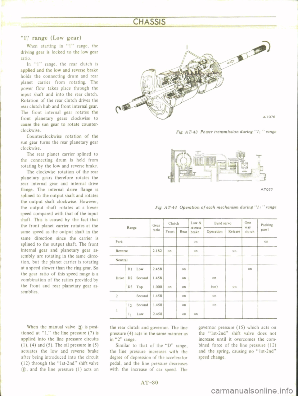
CHASSIS
1
range
Low
gear
When
starting
in
I
range
the
driving
gear
is
locked
to
the
low
gear
ratIO
In
1
range
the
reaT
dutch
is
applied
and
the
low
and
reverse
brake
holds
the
connecting
drum
and
rear
planet
carrier
from
rotating
The
power
flow
takes
place
through
the
input
shaft
and
into
the
rear
dutch
Rotation
of
the
rear
clutch
drives
the
rear
clutch
hub
and
front
internal
gear
The
front
internal
gear
rotates
the
front
planetary
gears
clockwise
to
cause
the
sun
gear
to
rotate
counter
clockwise
Counterclockwise
rotation
of
the
sun
gear
turns
the
rear
planetary
gear
clockwise
The
rear
planet
carrier
splined
to
the
connecting
drum
is
held
from
rotating
by
the
low
and
reverse
brake
The
clockwise
rotation
of
the
rear
planetary
gears
therefore
rotates
the
rear
internal
gear
and
internal
drive
tlange
The
internal
drive
tlange
is
splined
to
the
output
shaft
and
rotates
the
output
shaft
clockwise
However
the
output
shaft
rotates
at
a
lower
speed
compared
with
that
of
the
input
shaft
This
is
caused
by
the
fact
that
the
front
planet
carrier
rotates
at
the
same
speed
as
the
output
shaft
in
the
same
direction
since
the
carrier
is
splined
to
the
output
shaft
The
front
internal
gear
and
planetary
gear
as
sembly
are
rotating
in
the
same
direc
tion
but
the
planet
carrier
is
rotating
at
a
speed
slower
than
the
ring
gear
So
the
gear
ratio
of
this
speed
range
is
a
combination
of
the
ratios
provided
by
the
front
and
rear
planetary
gear
a
semblies
When
the
manual
valve
CV
is
posi
tioned
at
I
the
line
pressure
7
is
applied
into
the
line
pressure
circuits
I
4
and
5
The
oil
pressure
in
5
actuates
the
low
and
reverse
brake
after
being
introduced
into
the
circuit
12
through
the
lst
2nd
shift
valve
@
and
the
line
pressure
I
acts
on
i
C
AT076
Fig
A
T
43
Power
transmission
during
11
range
A
Ton
Fig
A
T
44
Operation
of
each
mechanism
during
11
range
Clutch
Low
Band
rvo
On
Parking
Range
Gm
ratio
reverse
w
pawl
Front
Rear
brake
Operation
Release
clutch
Park
on
on
Reverse
2
182
on
on
on
Neutral
DI
low
2
458
on
on
Drive
D2
Second
1
458
on
on
D
Top
1
000
on
on
on
on
2
Second
1
458
on
on
12
Second
1
458
on
on
I
Low
2
458
on
on
the
rear
clutch
and
governor
The
line
pressure
4
acts
in
the
same
manner
as
in
2
range
Similar
10
that
of
the
D
range
the
line
pressure
increases
with
the
degree
of
depressiun
of
the
accelerator
pedal
and
the
line
pressure
decreases
with
the
increase
of
car
speed
The
governor
pressure
IS
which
acts
on
the
Ist
2nd
shift
valve
does
not
increase
until
it
overcomes
the
com
bined
force
of
the
line
pressure
12
and
the
spring
causing
nu
I
st
2nd
speed
change
AT
3D
Page 36 of 513
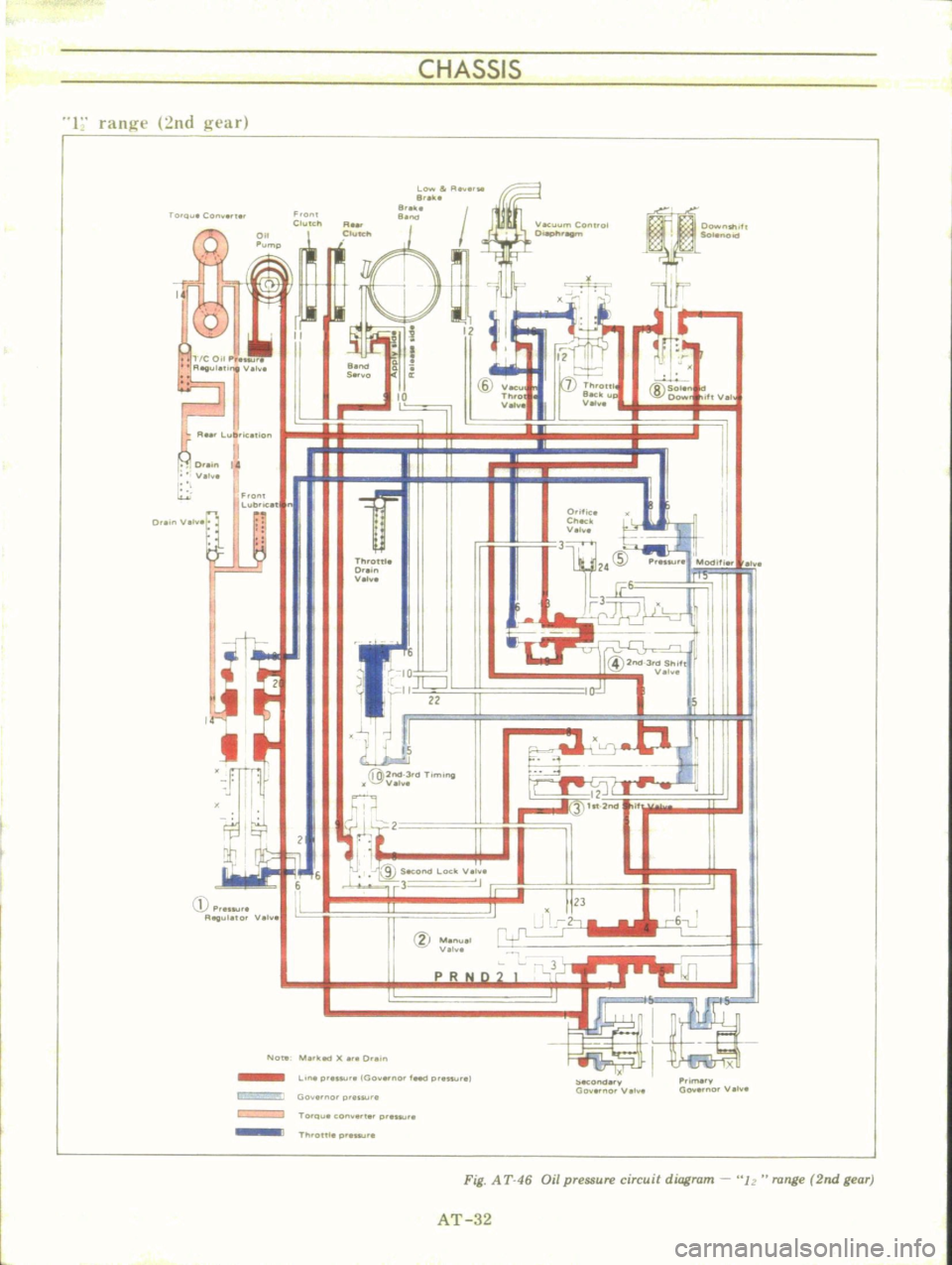
CHASSIS
1
rang
nd
gear
rOto
Con
I
Fro
l
ubHCll
II
1
Y
I
W
t
I
r
G
p
u
Reg
lle10
Ve
O
II
F
onl
Clutch
L
0Yw
r
e
e
e
a
eke
I
v
Th
o
Vel
O
f
e
ell
II
Vel
ThrOttle
0
v
31
J
lI
2
P
MP
M
lc
I
10
JCJ
rll
ZZ
I
IS
@2nd
3tdTlm
1J
V
h
@2nd3
d
ShIff
V
2
N
t
it
S
Of
d
L
ock
V
h
3
I
12
3
ht
2nd
6
6
lL
II
g
Mon
V
I
I
III
lIA
k
t
O
in
Hf
i
P
y
Gov
no
Vel
e
L
ne
pr
Go
no
feed
gt
Hu
ecOncl
y
00
0
Vel
Go
no
p
us
ur
TO
Qu
cony
g
Th
onlepr
swr
Fig
A
T
46
Oil
pressure
circuit
diagram
Iz
range
2nd
gear
AT
32
Page 41 of 513

AUTOMATIC
TRANSMISSIO
N
i
MAJOR
REPAIR
OPERATION
SERVICE
NOTICE
FOR
DISASSEMBLY
AND
ASSEMBLY
TORQUE
CONVERTER
Inspection
TRANSMISSION
Disassembly
Inspection
Assembly
SERVICE
NOTICE
FOR
DISASSEMBLY
AND
ASSEMBLY
I
It
is
desirable
that
the
repair
operations
are
carried
out
in
the
dust
proof
room
2
Due
to
the
differences
of
the
engine
capacities
the
specifications
of
component
parts
for
each
model
s
transmission
may
be
different
How
ever
they
do
have
common
adJust
ments
and
repair
as
well
as
cleaning
and
inspection
procedures
ou
tlined
hereinafter
3
During
the
repair
operations
refer
to
the
Service
Data
and
Specifi
cations
section
for
the
correct
parts
for
the
applicable
model
transmission
4
Before
removing
any
of
subas
semblies
thoroughly
clean
the
outside
of
the
transmission
to
preven
t
dirt
from
entering
the
mechanical
parts
5
Do
not
use
a
waste
rag
Use
a
nylon
waste
or
paper
waste
6
After
disassembling
wash
all
dis
assembled
parts
clean
and
examine
them
to
see
if
there
are
any
worn
damaged
or
defective
parts
and
how
they
are
affected
Refer
to
Service
Data
for
the
extent
of
damage
that
justifies
replacement
7
Packings
seals
and
similar
parts
once
disassembled
should
be
replaced
with
new
ones
as
a
rule
TORQUE
CONVERTER
CONTENTS
AT
37
AT
37
AT
37
AT
37
AT
37
AT
39
AT
39
COMPONENT
PARTS
F
rant
clutch
Rear
clutch
Low
reverse
brake
Servo
piston
Governor
Oil
pump
Planetary
carrier
Control
valve
The
torque
converter
is
a
welded
construction
and
can
not
be
disas
sembled
Inspection
I
Check
torque
converter
for
any
sign
of
damage
bending
oil
leak
or
deformation
If
necessary
replace
2
Remove
rust
from
pilots
and
bosses
completely
If
torque
converter
oil
is
fouled
or
contaminated
due
to
burnt
clutch
flush
the
torque
converter
as
follows
I
Drain
oil
in
torque
converter
2
Pour
none
Iead
gasoline
or
kero
sene
into
torque
converter
approxi
mately
0
5
liter
I
1
8
V
S
p
7
8
Imper
p
3
Blow
air
into
torque
converter
and
flush
and
drain
out
gasoline
4
Fill
torque
converter
oil
into
torque
converter
approximately
0
5
liter
I
i
8
I
pt
7
8
lmper
pt
5
Again
blow
air
into
torque
con
verter
and
drain
torque
converter
oil
TRANSMISSION
Disassembly
I
Drain
oil
from
the
end
of
rear
extension
Mount
transmission
on
Transmission
Case
Stand
ST07860000
or
ST07870000
Remove
oil
pan
See
Figure
AT
52
AT
37
T
AT
41
AT
41
AT
42
AT
43
AT
43
AT
44
AT
44
AT
45
AT
45
2
Remove
bolts
securing
converter
housing
to
transmission
case
Remove
torque
converter
3
Remove
speedometer
pinion
sleeve
boll
Withdraw
pinion
4
Turn
off
by
hand
downshift
sole
noid
and
vacuum
diaphragm
Do
not
leave
diaphragm
rod
at
this
stage
of
disassembly
Rod
is
assembled
in
top
of
vacuum
diaphragm
See
Figure
AT
53
ST07860000
AT118
Fig
AT
52
Remouing
oil
pan
Show
2
liter
engine
model
Fig
A
T
53
Downshift
solenoid
and
uacuum
diaphragm
Page 42 of 513
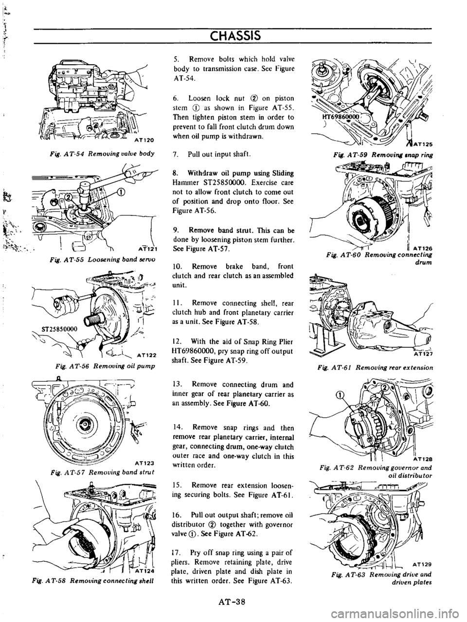
I
J
It
r
I
x
f
Fig
AT
54
Remouing
valve
body
tt
l
v
AT121
Fig
A
T
55
Loosening
band
en
a
Fig
AT
56
Removing
oil
pump
AT123
Fig
A
T
5
7
Removing
band
strut
Fig
A
T
SS
Removing
connecting
shell
CHASSIS
5
Remove
bolts
which
hold
valve
body
to
transmission
case
See
Figure
AT
54
6
Loosen
lock
nut
2
on
piston
stem
CI
as
shown
in
Figure
AT
55
Then
tighten
piston
stem
in
order
to
prevent
to
fall
front
clutch
drum
down
when
oil
pump
is
withdrawn
7
Pull
out
input
shaft
8
Withdraw
oil
pump
using
Sliding
Hammer
S125850000
Exercise
care
not
to
allow
front
clutch
to
come
out
of
position
and
drop
onto
floor
See
Figure
AT
56
9
Remove
band
strut
This
can
be
done
by
loosening
piston
stem
further
See
Figure
AT
57
10
Remove
brake
band
front
clutch
and
rear
clutch
as
an
assembled
unit
11
Remove
connecting
shelt
rear
clutch
hub
and
front
planetary
carrier
as
a
unit
See
Figure
AT
58
12
With
the
aid
of
Snap
Ring
Plier
HT69860000
pry
snap
ring
off
output
shaft
See
Figure
AT
59
13
Remove
connecting
drum
and
inner
gear
of
rear
planetary
carrier
as
an
assembly
See
Figure
AT
60
14
Remove
snap
rings
and
then
remove
rear
planetary
carrier
internal
gear
connecting
drum
one
way
clutch
outer
race
and
one
way
clutch
in
this
written
order
15
Remove
rear
extension
loosen
ing
securing
bolts
See
Figure
A
T
6I
16
Pull
out
output
shaft
remove
oil
distriburor
2
together
with
governor
valve
D
See
Figure
AT
62
17
Pry
off
snap
ring
using
a
pair
of
pliers
Remove
retaining
plate
drive
plate
driven
plate
and
dish
plate
in
this
written
order
See
Figure
AT
63
AT
38
Fig
AT
61
Removing
rear
extension
I
AT128
Fig
A
T
62
Removing
governor
and
oil
distributor
AT129
Fig
A
T
63
Removing
drive
and
driven
plates