1973 DATSUN B110 clutch
[x] Cancel search: clutchPage 335 of 513
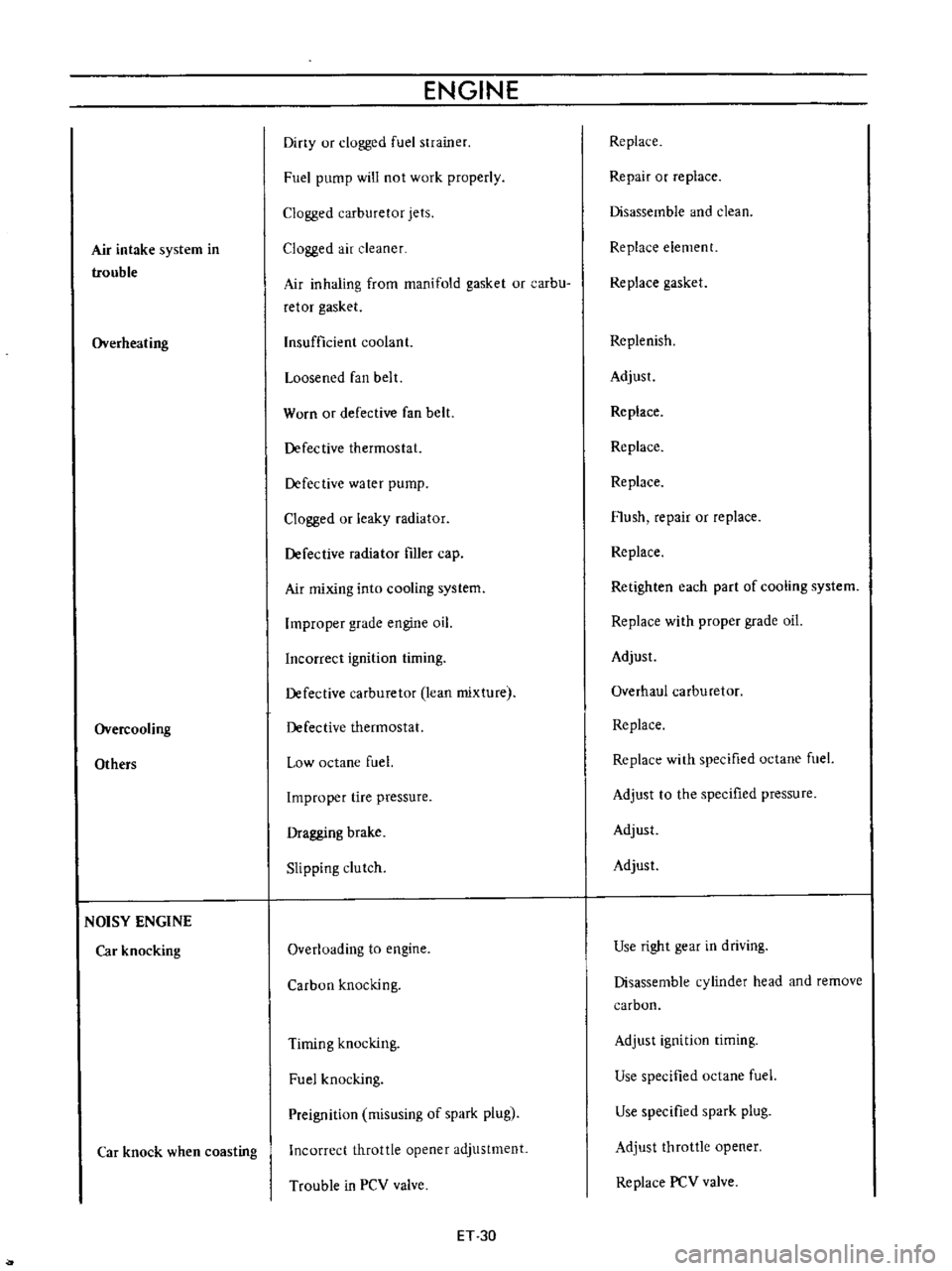
Air
intake
system
in
trouble
Overheating
Overcooling
Others
NOISY
ENGINE
Car
knocking
Car
knock
when
coasting
ENGINE
Diny
ur
clogged
fuel
strainer
Fuel
pump
will
not
work
properly
Clogged
carburetor
jets
Clogged
air
cleaner
Air
inhaling
from
manifold
gasket
or
carbu
retor
gasket
Insufficient
coolant
Loosened
fan
belt
Worn
or
defective
fan
belt
Defective
thermostat
Defective
water
pump
Clogged
or
leaky
radiator
Defective
radiator
filler
cap
Air
mixing
into
cooling
system
Improper
grade
engine
oil
Incorrect
ignition
timing
Defective
carburetor
lean
mixture
Defective
thermostat
Low
octane
fuel
Improper
tire
pressure
Dragging
brake
Slipping
clutch
Overloading
to
engine
Carbon
knocking
Timing
knocking
Fuel
knocking
Preignition
misusing
of
spark
plug
Incorrect
throttle
opener
adjustment
Trouble
in
PCV
valve
ET
30
Replace
Repair
or
replace
Disassemble
and
clean
Replace
element
Replace
gasket
Replenish
Adjust
Replace
Replace
Replace
Flush
repair
or
replace
Replace
Retighten
each
part
of
cooling
system
Replace
with
proper
grade
oil
Adjust
Overhaul
carburetor
Replace
Replace
with
specified
octane
fuel
Adjust
to
the
specified
pressure
Adjust
Adjust
Use
right
gear
in
driving
Disassemble
cylinder
head
and
remove
carbon
Adjust
ignition
timing
Use
specified
octane
fuel
Use
specified
spark
plug
Adjust
throttle
opener
Replace
PCV
valve
Page 336 of 513
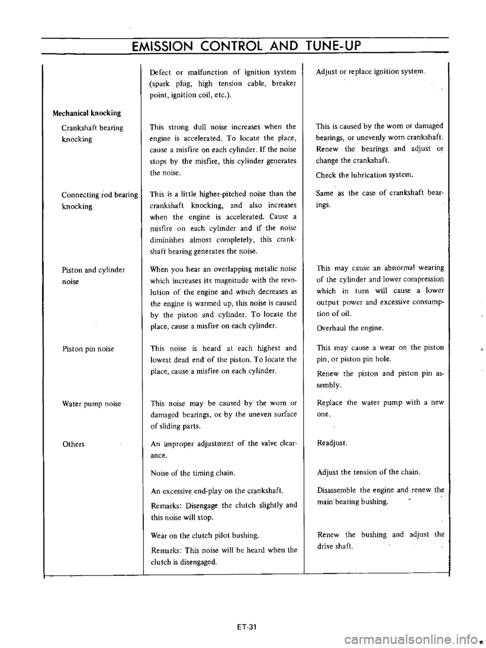
EMISSION
CONTROL
AND
TUNE
UP
Mechanical
knocking
Crankshaft
bearing
knocking
Connecting
rod
bearing
knocking
Piston
and
cylinder
noise
Piston
pin
noise
Water
pump
noise
Others
Defect
or
malfunction
of
ignition
system
spark
plug
high
tension
cable
breaker
point
ignition
coil
etc
This
strong
dull
noise
increases
when
the
engine
is
accelerated
To
locate
the
place
calise
a
misfire
on
each
cylinder
If
the
noise
stops
by
the
misfire
this
cylinder
generates
the
noise
This
is
a
little
higher
pitched
noise
than
the
crankshaft
knocking
and
also
increases
when
the
engine
is
accelerated
Cause
a
misfire
on
each
cylinder
and
if
the
noise
diminishes
almost
completely
this
crank
shaft
bearing
generates
the
noise
When
you
hear
an
overlapping
metalic
noise
which
increases
its
magnitude
with
the
revo
lution
of
the
engine
and
which
decreases
as
the
engine
is
warmed
up
this
noise
is
caused
by
the
piston
and
cylinder
To
locate
the
place
cause
a
misfire
on
each
cylinder
This
noise
is
heard
at
each
highest
and
lowest
dead
end
of
the
piston
To
locate
the
place
cause
a
misfire
on
each
cylinder
This
noise
may
be
caused
by
the
worn
or
damaged
bearings
or
by
the
uneven
surface
of
sliding
parts
An
improper
adjustment
of
the
valve
clear
ance
Noise
of
the
timing
chain
An
excessive
end
play
on
the
crankshaft
Remarks
Disengage
the
clutch
slightly
and
this
noise
will
stop
Wear
on
the
clutch
pilot
bushing
Remarks
This
noise
will
be
heard
when
the
clutch
is
disengaged
ET
31
Adjust
or
replace
ignition
syste
m
This
is
caused
by
the
wom
or
damaged
bearings
or
unevenly
worn
crankshaft
Renew
the
bearings
and
adjust
o
change
the
crankshaft
Check
the
lubrication
system
Same
as
the
case
of
crankshaft
bear
ings
This
may
cause
an
abnormal
wearing
of
the
cylinder
and
lower
compression
which
in
turn
will
cause
a
lower
output
power
and
excessive
consump
tion
of
oiL
Overhaul
the
engine
This
may
cause
a
wear
on
the
piston
pin
or
piston
pin
hole
Renew
the
piston
and
piston
pin
as
sembly
Replace
the
water
pump
with
a
new
one
Readjust
Adjust
the
tension
of
the
chain
Disassemble
the
engine
and
renew
the
main
bearing
bushing
Renew
the
bushing
and
adjust
the
drive
shaft
Page 344 of 513
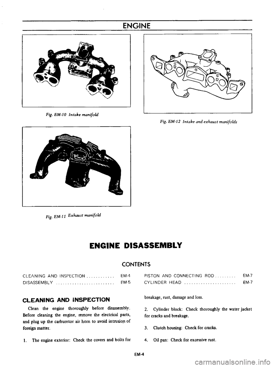
ENGINE
Fig
EM
IO
Intake
manifold
Fig
EM
12
Intake
and
exhaust
manifolds
Fig
EM
It
Exhaust
manifold
ENGINE
DISASSEMBLY
CONTENTS
CLEANING
AND
INSPECTION
DISASSEMBL
Y
EM
4
EM
5
PISTON
AND
CONNECTING
ROD
CYLINDER
HEAD
EM
7
EM
7
CLEANING
AND
INSPECTION
breakage
rust
damage
and
loss
Clean
the
engine
thoroughly
before
disassembly
Before
cleaning
the
engine
remove
the
electrical
parts
and
plug
up
the
carburetor
air
horn
to
avoid
intrusio
n
of
foreign
matter
2
Cylinder
block
Check
thoroughly
the
water
jacket
for
cracks
and
breakage
3
Clutch
howing
Check
for
cracks
1
The
engine
exterior
Check
the
covers
and
bolts
for
4
Oil
pan
Check
for
excessive
rust
EM
4
Page 365 of 513
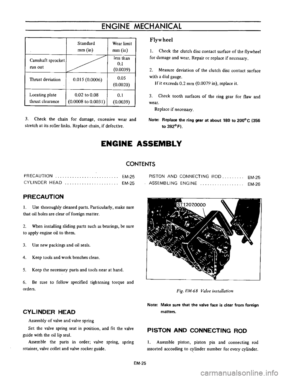
ENGINE
MECHANICAL
Standard
mm
in
Camshaft
sprocket
run
out
Thrust
deviation
O
OIS
0
0006
Locating
plate
thrust
clearance
0
02
to
0
08
0
0008
to
0
003
Wear
limit
mm
in
less
than
0
0
0039
O
OS
0
0020
0
1
0
0039
3
Check
the
chain
for
damage
excessive
wear
and
stretch
at
its
roller
links
Replace
chain
if
defective
Flyw
heel
I
Check
the
clutch
disc
contact
surface
of
the
flywheel
for
damage
and
wear
Repair
or
replace
if
necessary
2
Measure
deviation
of
the
clutch
disc
contact
surface
with
a
dial
gauge
If
it
exceeds
0
2
mm
0
0079
in
replace
it
3
Check
tooth
surfaces
of
the
ring
gear
for
flaw
and
wear
Replace
if
necessary
Note
Replace
the
ring
gear
at
about
180
to
2000C
356
to
3920
Fl
ENGINE
ASSEMBLY
PRECAUTION
CYLINDER
HEAD
PRECAUTION
CONTENTS
EM
25
EM
25
Use
thoroughly
cleaned
parts
Particularly
make
sure
that
oil
holes
are
clear
of
foreign
matter
2
When
installing
sliding
parts
such
as
bearings
be
sure
to
apply
engine
oil
to
them
3
Use
new
packings
and
oil
seals
4
Keep
tools
and
work
benches
clean
S
Keep
the
necessary
parts
and
tools
near
at
hand
6
Be
sure
to
follow
specified
tightening
torque
and
orders
CYLINDER
HEAD
Assembly
of
valve
and
valve
spring
Set
the
valve
spring
seat
in
position
and
fit
the
valve
guide
with
the
oil
lip
seal
Assemble
the
parts
in
order
valve
spring
spring
retainer
valve
collet
and
valve
rocker
guide
PISTON
AND
CONNECTING
ROO
ASSEMBLING
ENGINE
EM
25
EM
26
I
I
11
00
I
I
I
t
I
J
ftr
J
J
1
l
J
r
N
1
n
r
VI
I
I
C
I
L
I
Fig
EM
68
Valve
installation
Note
Make
sure
that
the
valve
face
is
clear
from
foreign
matters
PISTON
AND
CONNECTING
ROD
Assemble
piston
piston
pin
and
connecting
rod
assorted
according
to
cylinder
number
for
every
cylinder
EM
25
Page 372 of 513
ENGINE
27
Install
the
oil
pump
with
oil
filter
28
Install
the
alternator
fan
and
fan
belt
29
Install
the
fuel
pump
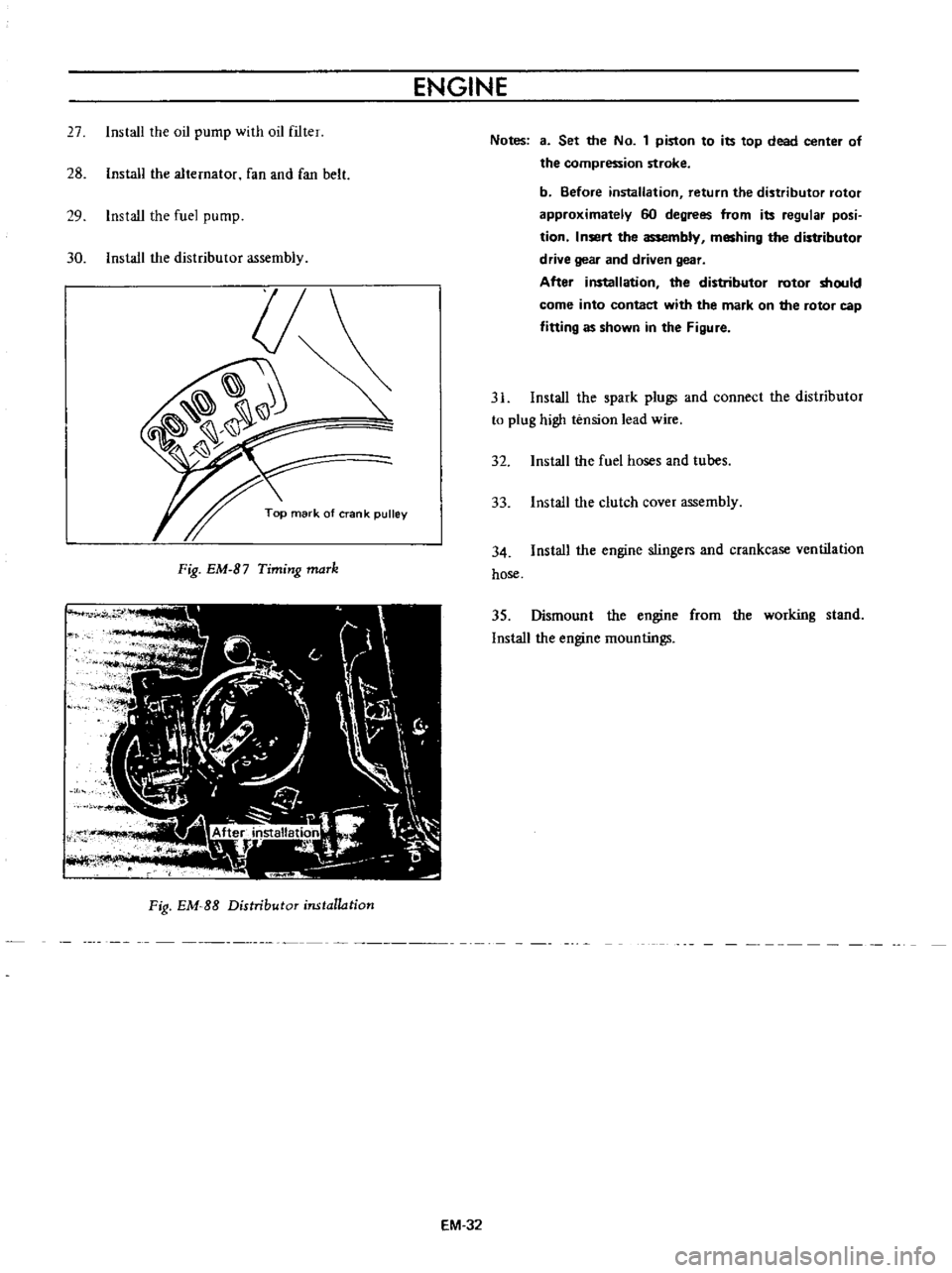
30
Install
the
distributor
assembly
Fig
EM
B7
Timing
maTk
Fig
EM
SS
Distributor
installation
EM
32
Notes
3
Set
the
No
1
piston
to
its
top
dead
center
of
the
compression
stroke
b
Before
installation
return
the
distributor
rotor
approximately
60
degrees
from
its
regular
posi
tion
Insert
the
assembly
meshing
the
distributor
drive
gear
and
driven
gear
After
installation
the
distributor
rotor
should
come
into
contact
with
the
mark
on
the
rotor
cap
fitting
as
shown
in
the
Figure
31
Install
the
spark
plugs
and
connect
the
distributor
to
plug
high
tension
lead
wire
32
Install
the
fuel
hoses
and
tubes
33
Install
the
clutch
cover
assembly
34
Install
the
engine
stingers
and
crankcase
ventilation
hose
35
Dismount
the
engine
from
the
working
stand
Install
the
engine
mountings
Page 423 of 513
ENGINE
ElECTRICAL
SYSTEM
5
If
the
specific
gravity
is
above
1
260
200C
or
680F
after
charging
adjust
it
by
adding
distilled
water
6
Keep
any
open
flame
away
from
the
place
where
the
battery
is
being
charged
7
Replace
vent
plugs
and
clean
the
upper
face
of
the
battery
after
charging
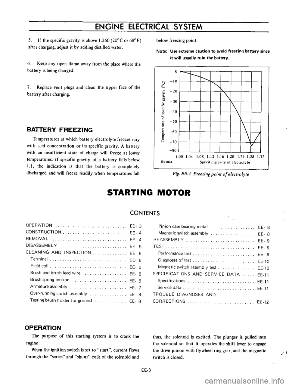
BATTERY
FREEZING
Temperatures
at
which
battery
electrolyte
freezes
vary
with
acid
concentration
or
its
specific
gravity
A
battery
with
an
insufficient
state
of
charge
will
freeze
at
lower
temperatures
If
specific
gravity
of
a
battery
falls
below
I
I
the
indication
is
that
the
battery
is
completely
discharged
and
will
freeze
readily
when
temperatures
fall
below
freezing
point
Note
Use
extreme
caution
to
avoid
freezing
battery
since
it
will
usually
ruin
the
battery
o
I
I
1
G
10
I
1
o
i
20
I
u
30
I
I
0
40
I
0
SO
I
60
0
I
E
f
o
70
I
80
1
00
1
04
1
08
I
12
1
16
20
24
1
28
1
32
E
E004
Specific
gravity
of
electrolyte
Fig
EE
4
FTeezing
point
of
electrolyte
STARTI
NG
MOTOR
CONTENTS
OPERATION
CONSTRUCTION
REMOVAL
DISASSEMBL
Y
CLEANING
AND
INSPECTION
Terminal
Field
coil
Brush
and
brush
lead
wire
Brush
spring
tension
Armature
assembly
Over
running
clutch
assembly
Testing
brush
holder
for
ground
EE
3
EE
4
EE
4
EE
5
EE
6
EE
6
EE
6
EE
6
EE
6
EE
7
EE
8
EE
8
OPERATION
The
purpose
of
this
starting
system
is
to
crank
the
engine
When
the
ignition
switch
is
set
to
start
current
flows
through
the
series
and
shunt
coils
of
the
solenoid
and
Pinion
case
bearing
metal
Magnetic
switch
assembly
REASSEMBL
Y
TESr
Performance
test
Diagnoses
of
test
Magnetic
switch
assembly
test
SPECIFICATIONS
AND
SERVICE
DATA
Specifications
Service
data
TROU8LE
DIAGNOSES
AND
CORRECTIONS
EE
8
EE
8
EE
9
EE
9
EE
g
EE
10
EE
10
EE
11
EE
11
EE
11
EE
12
thus
the
solenoid
is
excited
The
plunger
is
pulled
into
the
solenoid
so
that
it
operates
the
shift
lever
to
engage
the
drive
pinion
with
flywheel
ring
gear
and
the
magnetic
switch
is
closed
EE
3
Page 424 of 513
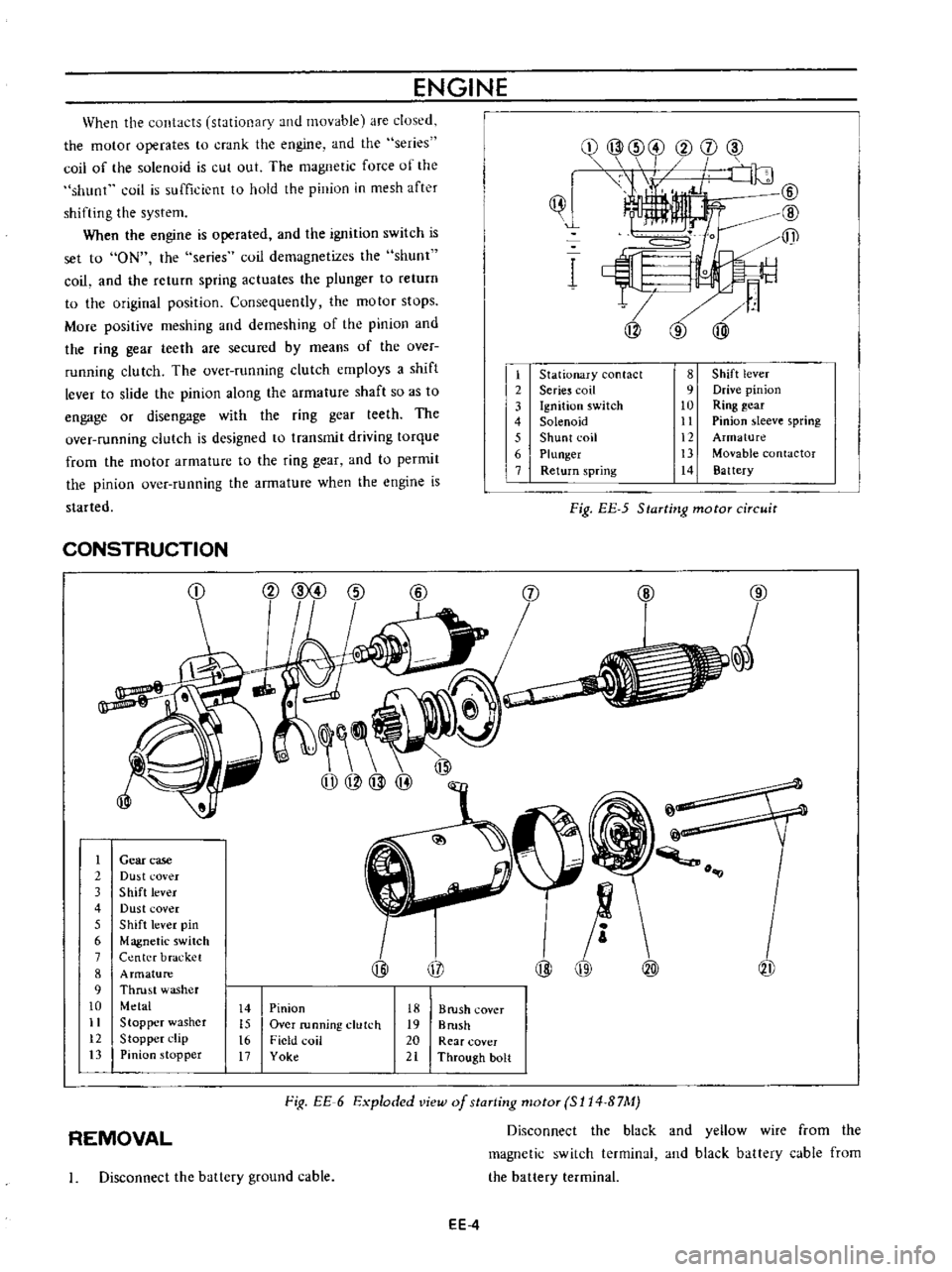
When
the
contacts
stationary
and
movable
are
dused
the
motor
operates
to
crank
the
engine
and
the
series
coil
of
the
solenoid
is
cut
out
The
magnetic
force
of
the
shunt
coil
is
sufficient
to
hold
the
pinion
in
mesh
after
shifting
the
system
When
the
engine
is
operated
and
the
ignition
switch
is
set
to
ON
the
series
coil
demagnetizes
the
shunt
coil
and
the
return
spring
actuates
the
plunger
to
return
to
the
original
position
Consequently
the
motor
stops
More
positive
meshing
and
demeshing
of
the
pinion
and
the
ring
gear
teeth
are
secured
by
means
of
the
over
running
clutch
The
over
running
clutch
employs
a
shift
lever
to
slide
the
pinion
along
the
armature
shaft
so
as
to
engage
or
disengage
with
the
ring
gear
teeth
The
over
running
clutch
is
designed
to
transmit
driving
torque
from
the
motor
armature
to
the
ring
gear
and
to
permit
the
pinion
over
running
the
armature
when
the
engine
is
started
ENGINE
ijJ
1
t
2
3
4
5
6
7
Stationary
contact
Serie
coil
Ignition
switch
Solenoid
Shunt
coil
Plunger
Return
spring
8
Shift
lever
9
Drive
pinion
10
Ring
gear
11
Pinion
sleeve
spring
12
Armature
13
Movable
contactor
14
Battery
Fig
EE
5
Starting
motor
circuit
CONSTRUCTION
1
2
3
4
5
6
7
8
9
10
11
12
13
j
@
Gear
case
Du
t
cover
Shift
lever
Dust
cover
Shift
lever
pin
Magnetic
switch
Center
bracket
Armature
Thrust
washer
Metal
Stopper
washer
Stopper
l
lip
Pinion
stopper
@
@
o
@
i
1I
@
@
@
14
15
t6
17
Pinion
Over
running
clutch
Field
coil
Yoke
18
B
rush
cover
19
Brush
20
Rear
cover
21
Through
bolt
Fig
EE
6
Exploded
view
of
staTting
motoT
SI14
B7M
Disconnect
the
black
and
yellow
wire
from
the
magnetic
switch
terminal
and
black
battery
cable
from
the
battery
terminal
REMOVAL
I
Disconnect
the
ballery
ground
cable
EE
4
Page 425 of 513
ENGINE
ELECTRICAL
SYSTEM
2
Remove
two
bolts
llsed
to
secure
the
starting
motor
on
the
clutch
housing
Pull
the
starter
assembly
forward
and
remove
the
starting
motor
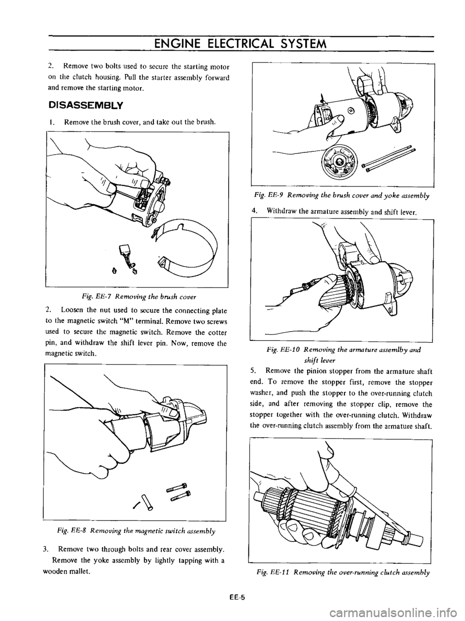
DISASSEMBLY
Remove
the
brush
cover
and
take
out
the
brush
6
Fig
EE
7
Removing
the
brush
cover
2
Loosen
the
nut
used
to
secure
the
connecting
plate
to
the
magnetic
switch
M
terminal
Remove
two
screws
used
to
secure
the
magnetic
switch
Remove
the
cotter
pin
and
withdraw
the
shift
lever
pin
Now
remove
the
magnetic
switch
Fig
EE
8
Removing
the
magnetic
switch
assembly
3
Remove
two
through
bolts
and
rear
cover
assembly
Remove
the
yoke
assembly
by
lightly
tapping
with
a
wooden
mallet
Fig
EE
9
Removing
the
brush
cover
and
yoke
assembly
4
Withdraw
the
armature
assembly
and
shift
lever
Fig
EE
l0
Removing
the
armature
assemlby
and
shift
lever
5
Remove
the
pinion
stopper
from
the
armature
shaft
end
To
remove
the
stopper
first
remove
the
stopper
washer
and
push
the
stopper
to
the
over
running
clutch
side
and
after
removing
the
stopper
clip
remove
the
stopper
together
with
the
over
running
clutch
Withdraw
the
over
running
clutch
assembly
from
the
armature
shaft
Fig
EE
11
Removing
the
over
running
clutch
assembly
EE
5