Page 129 of 432

Instruments and Controls3
Instruments and Controls
3-1. Push-Button Ignition Switch ..............................125
Safety Precautions ............................................ ...........125
Operating Range for Push-Button Start System .......125
Switching Power Status ...............................................125
When Access Key Fob Does Not Operate
Properly.......................................................................126
3-2. Hazard Warning Flasher .....................................127
3-3. Meters and Gauges .............................................127
Speedometer .................................................................127
Tachometer ...................................................................127
Odometer and Double Trip Meter................................128
Fuel Gauge ....................................................................129
Engine Coolant Temperature Gauge ..........................129
Outside Temperature ...................................................129
Combination Meter Settings ........................................130
3-4. REV indicator light and buzzer ..........................130
3-5. Illumination Brightness Control ........................130
Auto Dimmer Cancel Function ....................................131
3-6. Warning and Indicator Lights ............................131
Seatbelt Warning Light and Chime .............................131
SRS Airbag System Warning Light .............................135
Front Passenger’s Frontal Airbag ON and OFF Indicators ....................................................................135
CHECK ENGINE Warning Light/Malfunction
Indicator Light ............................................................136
Coolant Temperature Low Indicator Light/Coolant Temperature High Warning Light .............................136
Charge Warning Light ..................................................137
Oil Pressure Warning Light .........................................137
AT OIL TEMP Warning Light (AT Models) .................138
Low Tire Pressure Warning Light (If Equipped) ........138
ABS Warning Light .......................................................140
Brake System Warning Light... ....................................140Low Fuel Warning Light .............................................. 141
Door Open Indicator .................................................... 141
Power Steering Warning Light ................................... 141
TRAC OFF Indicator Light........................................... 142
Vehicle Stability Control (VSC) Warning Light/
Vehicle Stability Control (VSC) Operation
Indicator Light............................................................ 142
Vehicle Stability Control (VSC) OFF Indicator
Light ........................................................................... 143
Warning Chimes and Warning Indicator of the
Keyless Access with Push-Button Start System.... 143
Security Indicator Light............................................... 148
Drive Mode Indicator Light (If Equipped) .................. 148
Select Lever (AT Models Only)/Gear Position
Indicator ..................................................................... 149
Cruise Control Indicator Light (White/Green)/
Cruise Control Warning Light (Yellow) (Models
without the EyeSight System) .................................. 149
Turn Signal Indicator Lights ....................................... 149
High Beam Indicator Light .......................................... 150
High Beam Assist Indicator (If Equipped) ................. 150
Automatic Headlight Beam Leveler Warning
Light ............................................................................ 150
LED Headlight Warning Light ..................................... 150
Steering Responsive Headlight OFF Indicator
Light (If Equipped) ..................................................... 150
Steering Responsive Headlight Warning Light
(If Equipped)............................................................... 150
Headlight Indicator Light ............................................ 150
Hill Start Assist Indicator Light .................................. 150
BSD/RCTA Warning Indicator (If Equipped).............. 150
BSD/RCTA OFF Indicator (If Equipped) ..................... 150
Icy Road Surface Warning Indicator .......................... 151
BRZ_U.book 123 ページ 2022年3月29日 火曜日 午後3時59分
Page 130 of 432

Instruments and Controls
RAB Warning Indicator (If Equipped) ......................... 151
RAB OFF Indicator (If Equipped) ................................ 151
Master Warning Light .................................................. 151
3-7. Combination Meter Display (Color TFT) ...........151
Basic Operation............................................................ 152
Meter Information Screen ........ .................................... 152
Drive Information ......................................................... 153
Exclusive Content for SUBARU BRZ ......................... 154
Navigation System-Linked Disp lay ............................ 156
Audio System-Linked Display..................................... 156
Driving Support System Settings Display ................. 157
Settings Display ........................................................... 157
Warning Message Display ....... .................................... 159
Telltale Screen .............................................................. 159
3-8. Center Information Display (CID).......................160
Features ........................................................................ 160
Touch Screen Operations ........................................... 160
Main Screen .................................................................. 161
3-9. Clock ....................................................................172
Setting the Clock Manually ......................................... 172
Setting the Clock Automatically ................................. 173
3-10. Light Control Switch ........................................ 174
Headlights ..................................................................... 174
High/Low Beam Change (Dimmer) ............................. 176
Headlight Flasher ......................................................... 176
High Beam Assist Function (If Equipped).................. 177
Daytime Running Light System .................................. 180
3-11. Steering Responsive Headlight (SRH)
(If Equipped) ..................................................... 180
3-12. Headlight Beam Leveler .................................. 182
3-13. Turn Signal Le ver ............................................. 182
One-Touch Lane Changer ........................................... 182
3-14. Wiper and Washer ............................................ 183
Windshield Wiper and Washer Switches ................... 184
3-15. Defogger ........................................................... 185
3-16. Mirrors ............................................................... 186
Inside Mirror.................................................................. 186
Auto-Dimming Mirror/Compass with HomeLink
®
(Dealer Option) ........................................................... 186
Outside Mirrors............................................................. 194
3-17. Tilt/Telescopic Steering Wheel ....................... 195
3-18. Horn ................................................................... 195
BRZ_U.book 124 ページ 2022年3月29日 火曜日 午後3時59分
Page 131 of 432

Push-Button Ignition Switch
125
Instruments and Controls3
– CONTINUED –
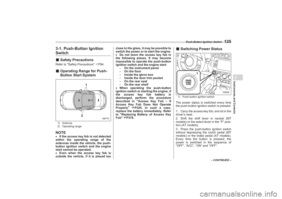
3-1. Push-Button Ignition Switch■Safety PrecautionsRefer to "Safety Precautions" P94.■ Operating Range for Push-
Button Start System1) Antenna
2) Operating rangeNOTEIf the access key fob is not detected
within the operating range of the
antennas inside the vehicle, the push-
button ignition switch and the engine
start cannot be operated.
Even when the access key fob is
outside the vehicle, if it is placed too close to the glass, it may be possible to
switch the power or to start the engine.
Do not leave the access key fob in
the following places. It may become
impossible to operate the push-button
ignition switch and the engine start. - On the instrument panel
- On the floor
- Inside the glove box
- Inside the door trim pocket
- On the rear seat
- On the rear shelf
When operating the push-button
ignition switch or starting the engine, if
the access key fob battery is
discharged, perform the procedure
described in "Access Key Fob – If
Access Key Fob Does Not Operate
Properly" P325. In such a case,
replace the battery immediately. Refer
to "Replacing Battery of Access Key
Fob" P376.
■ Switching Power Status1) Push-button ignition switchThe power status is switched every time
the push-button ignition switch is pressed.
1. Carry the access key fob, and sit in the
driver’s seat.
2. Shift the shift lever in neutral (MT
models) or the select lever in the “P” posi-
tion (AT models).
3. Press the push-button ignition switch
without depressing the clutch pedal (MT
models) or the brak e pedal (AT models).
Every time the button is pressed, the
power is switched in the sequence of
“OFF”, “ACC”, “ON” and “OFF”.
1
2
306779
1
702836
BRZ_U.book 125 ページ 2022年3月29日 火曜日 午後3時59分
Page 132 of 432

Push-Button Ignition Switch
126
NOTEWhen operating the push-button
ignition switch, firmly press it all the
way.
If the push-button ignition switch is
pressed quickly, the power may not
turn on or off.
When the steering lock cannot be
released, the message appears on the
combination meter. When this occurs,
press the push-butto n ignition switch
while turning the steering wheel left
and right.
▼ Battery drainage prevention func -
tion
When the push-button ignition switch is
left in the “ACC” for more than 20 minutes
or “ON” position for approximately 1 hour,
the push-button ignition switch will be
automatically switched to “OFF” to
prevent the battery from going dead. (In
AT models, this function is activated when
the select lever is in the “P” position.)■ When Access Key Fob Does
Not Operate ProperlyRefer to "Access Key Fob – If Access Key
Fob Does Not Operate Properly" P325.
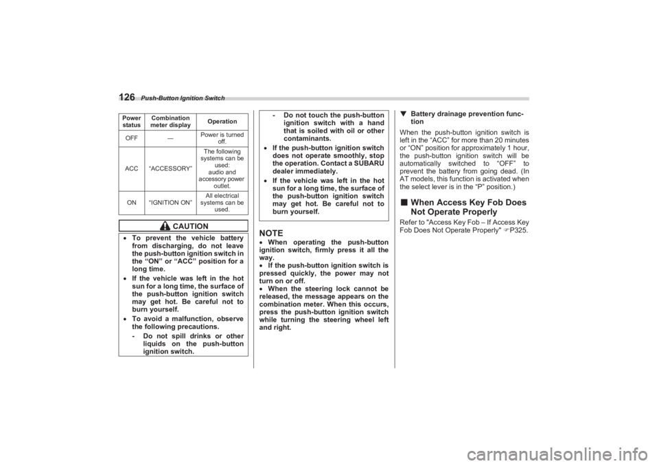
Power
status Combination
meter display Operation
OFF ―Power is turned
off.
ACC “ACCESSORY” The following
systems can be
used:
audio and
accessory power
outlet.
ON “IGNITION ON” All electrical
systems can be used.
CAUTION
To prevent the vehicle battery
from discharging, do not leave
the push-button ig nition switch in
the “ON” or “ACC” position for a
long time. If the vehicle was left in the hot
sun for a long time, the surface of
the push-button ignition switch
may get hot. Be careful not to
burn yourself. To avoid a malfunction, observe
the following precautions.
- Do not spill drinks or other
liquids on the push-button
ignition switch.
- Do not touch the push-button
ignition switch with a hand
that is soiled with oil or other
contaminants.
If the push-button ignition switch
does not operate smoothly, stop
the operation. Contact a SUBARU
dealer immediately. If the vehicle was left in the hot
sun for a long time, the surface of
the push-button ignition switch
may get hot. Be careful not to
burn yourself.
BRZ_U.book 126 ページ 2022年3月29日 火曜日 午後3時59分
Page 133 of 432

Hazard Warning Flasher
127
Instruments and Controls3
– CONTINUED –
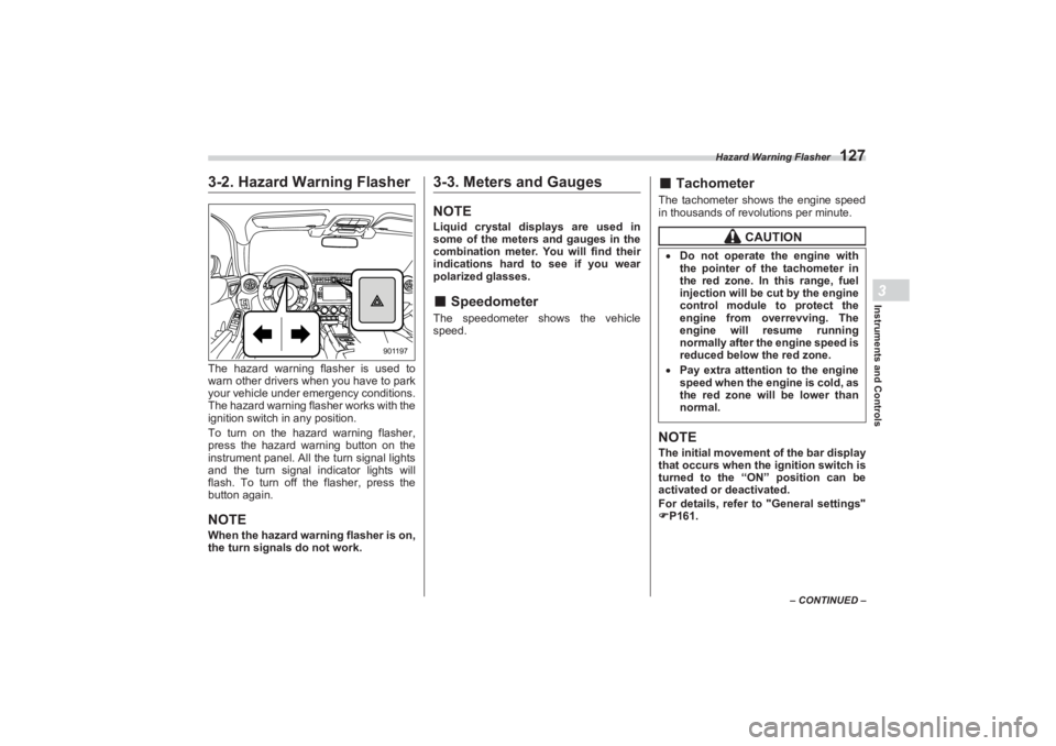
3-2. Hazard Warning FlasherThe hazard warning flasher is used to
warn other drivers when you have to park
your vehicle under emergency conditions.
The hazard warning fl asher works with the
ignition switch in any position.
To turn on the hazard warning flasher,
press the hazard warning button on the
instrument panel. All the turn signal lights
and the turn signal indicator lights will
flash. To turn off the flasher, press the
button again.NOTEWhen the hazard warning flasher is on,
the turn signals do not work.
3-3. Meters and GaugesNOTELiquid crystal displays are used in
some of the meters and gauges in the
combination meter. You will find their
indications hard to see if you wear
polarized glasses.■ SpeedometerThe speedometer shows the vehicle
speed.
■ TachometerThe tachometer shows the engine speed
in thousands of revolutions per minute.NOTEThe initial movement of the bar display
that occurs when the ignition switch is
turned to the “ON” position can be
activated or deactivated.
For details, refer to "General settings"
P161.
901197
CAUTION
Do not operate the engine with
the pointer of the tachometer in
the red zone. In this range, fuel
injection will be cut by the engine
control module to protect the
engine from overrevving. The
engine will resume running
normally after the engine speed is
reduced below the red zone. Pay extra attention to the engine
speed when the engine is cold, as
the red zone will be lower than
normal.
BRZ_U.book 127 ページ 2022年3月29日 火曜日 午後3時59分
Page 134 of 432

Meters and Gauges
128■Odometer and Double Trip
Meter1) TRIP RESET switch
2) Odometer
3) Trip meterThis meter displays the odometer/trip
meter when the ignition switch is in the
“ON” position.
The display can be switched as shown in
the following sequence by pressing the
TRIP RESET switch. To reset the trip meter, select either the A
trip or B trip meter, then press and hold the
TRIP RESET switch.
▼ Odometer
The odometer shows the total distance
that the vehicle has been driven.
NOTEIf you press the TRIP RESET switch
when the ignition switch is in the
“OFF” or “ACC” po sition, the odome-
ter/trip meter will light up. The indica-
tors will turn off when the TRIP RESET
switch is not operated for approxi-
mately 10 seconds. ▼
Double trip meter
The trip meter shows the distance that the
vehicle has been driven since you last set
it to zero.NOTE If the connection between the
combination meter and battery is
broken for any reason such as vehicle
maintenance or fuse replacement, the
data recorded on the trip meter will be
lost.
If you press the TRIP RESET switch
when the ignition switch is in the
“OFF” or “ACC” position, the odom-
eter/trip meter will light up. It is
possible to switch between the A trip
meter and B trip meter indications
while the odometer/trip meter is lit up.
1
23
306781
306961
CAUTION
To ensure safety, do not attempt to
change the function of the indicator
during driving, as an accident could
result.
BRZ_U.book 128 ページ 2022年3月29日 火曜日 午後3時59分
Page 135 of 432

Meters and Gauges
129
Instruments and Controls3
– CONTINUED –
■Fuel GaugeThe fuel gauge shows the approximate
amount of fuel remaining in the tank.
When the ignition switch is in the “OFF” or
“ACC” position, the fuel gauge shows “E”
even if the fuel tank contains fuel.
The gauge may move slightly due to fuel
level movement in the tank (e.g., during
braking, turning or acceleration).NOTEYou will see the “ ” sign in the fuel
gauge. This indicates that the fuel filler
lid is located on the right side of the
vehicle.
■ Engine Coolant Temperature
GaugeThe temperature gauge shows engine
coolant temperature when the ignition
switch is in the “ON” position.
The coolant temperature will vary in
accordance with the outside temperature
and driving conditions.
We recommend that you drive moderately
until the pointer of the temperature gauge
reaches near the middle of the range.
Engine operation is optimum with the
engine coolant at this temperature range
and high revving operation when the
engine is not warmed up enough should
be avoided.
■ Outside TemperatureDisplays the outside temperature within
the range of -40°F (-40°C) to 122°F
(50°C). Low outside temperature indicator
comes on when the ambient temperature
is 37°F (3°C) or lower.NOTEThe outside temperature indicator
shows the temperature around the
sensor. However, the temperature may
not be indicated correctly or the
update may be delayed in the follow-
ing conditions.
While parking or driving at low
speeds
When the outside temperature
changes suddenly (example: when
going in and out of an underground
parking area or when passing through
a tunnel)
When starting the engine after being
parked for a certain period of time
306783
B02099
CAUTION
If the pointer exceeds the normal
operating range, safely stop the
vehicle as soon as possible.Refer to "Engine Overheating"
P319.
BRZ_U.book 129 ページ 2022年3月29日 火曜日 午後3時59分
Page 136 of 432

REV indicator light and buzzer
130■Combination Meter SettingsSome meter settings can be set on the
center information display. For details,
perform the procedures described in
"General settings" P161.
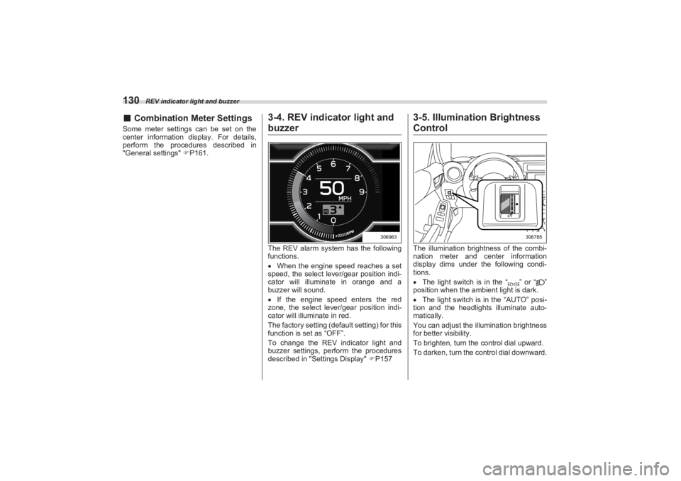
3-4. REV indica tor light and buzzerThe REV alarm system has the following
functions.
When the engine speed reaches a set
speed, the select lever/gear position indi-
cator will illuminate in orange and a
buzzer will sound.
If the engine speed enters the red
zone, the select lever/gear position indi-
cator will illuminate in red.
The factory setting (default setting) for this
function is set as “OFF”.
To change the REV indicator light and
buzzer settings, perform the procedures
described in "Settings Display" P157
3-5. Illumination Brightness ControlThe illumination brightness of the combi-
nation meter and center information
display dims under the following condi-
tions.
The light switch is in the “ ” or “ ”
position when the ambient light is dark.
The light switch is in the “AUTO” posi-
tion and the headlights illuminate auto-
matically.
You can adjust the illumination brightness
for better visibility.
To brighten, turn the control dial upward.
To darken, turn the control dial downward.
306963
306785
BRZ_U.book 130 ページ 2022年3月29日 火曜日 午後3時59分