Page 265 of 392

2581Turn the ignition switch to LOCK.
2Loosen the negative terminal cable from the battery and wait for over 1 minute.
3Remove the glove box.
4Loosen the passenger airbag assembly connectors.
5Is the connector of the passenger airbag assembly normal?
Normal: [DTC of present trouble]
Continue with next step.
[DTC of past trouble]
Continue with next step.
Abnormal: replace the wire harness.
(3) Ascertain the trouble exists in passenger airbag assembly or other part
1Connect a new assembly to terminals A and B of the connector of passenger airbag assembly.
2Connect the negative (-) terminal cable of the battery.
3Turn the ignition switch ON.
4Any DTC displayed? Can it be cleared?
No: continue with next step.
Yes: replace passenger airbag assembly
See SRS- Passenger Airbag Assembly, Removal & Installation.
(4) Check the wire harness between passenger airbag assembly and SRS ECU
1Turn the ignition switch to LOCK.
2Loosen the negative (-) terminal cable from the battery and wait for over 1 minute.
3Remove steering column hood.
4Loosen the connector of the clock spring.
5Loosen the connectors of driver and passenger airbag assemblies.
6Remove left trim plate.
7Loosen all the SRS unit connectors.
8Check the circuit between the connector terminals of the SRS ECU and that of passenger airbag assembly
and the circuit between the connector terminal of the SRS unit and that of passenger airbag assembly for
the following:
yGround.
yShort circuit with power source.
yOpen circuit.
9Are the above-mentioned wire harnesses normal?
Normal: completion of trouble diagnosis.
Abnormal: replace the related wire harness.
Page 266 of 392

259III. DIAGNOSIS OF CRASHED VEHICLEsWhether the SRS is deployed or not, the checking and maintenance of the crashed vehicle shall be carried
out according to the following procedures.
1. Check the diagnostic signal of ECU
(1) Connect the check connector of the Hi-DS T Scan Meter.
(2) Read out the diagnostic results from Hi-DS T Scan Meter.
2. Repair procedures
(1) When the SRS is deployed, the following parts shall be renewed.
1Passenger airbag assembly.
2ECU.
3Driver airbag assembly.
Check the following parts, if abnormal, replace with new ones.
1Clock spring.
2Steering wheel, steering column and steering lower shaft
component.
The installation status of driver airbag assembly in relation to steering wheel.
1Check and see if there is abnormal noise in the steering wheel, the action of the same is good,
or the clearance is normal.
2Check the union joint of the wire harness for damage and the terminal for distortion.
3. ECU
(1) Check the brackets of the ECU Case for recess, crack, distortion, etc.
(2) Check the union joint for damage and terminal for distortion.
(3) Check the installation status of he ECU brackets
1Check the hood for recess, crack, distortion, etc.
2Check the union joint for damage, terminal for distortion
and wire harness for seizure.
3Check the case of the gas generator for recess,
crack and distortion.NOTICE
Due to shock, when the battery power
supply is insufficient, the scan Meter
cannot communicate with ECU, the
instrument panel wire harness shall be
checked and maintained or external
power source shall be used.
Page 267 of 392

260(4) Check the installation status of the airbag assembly.
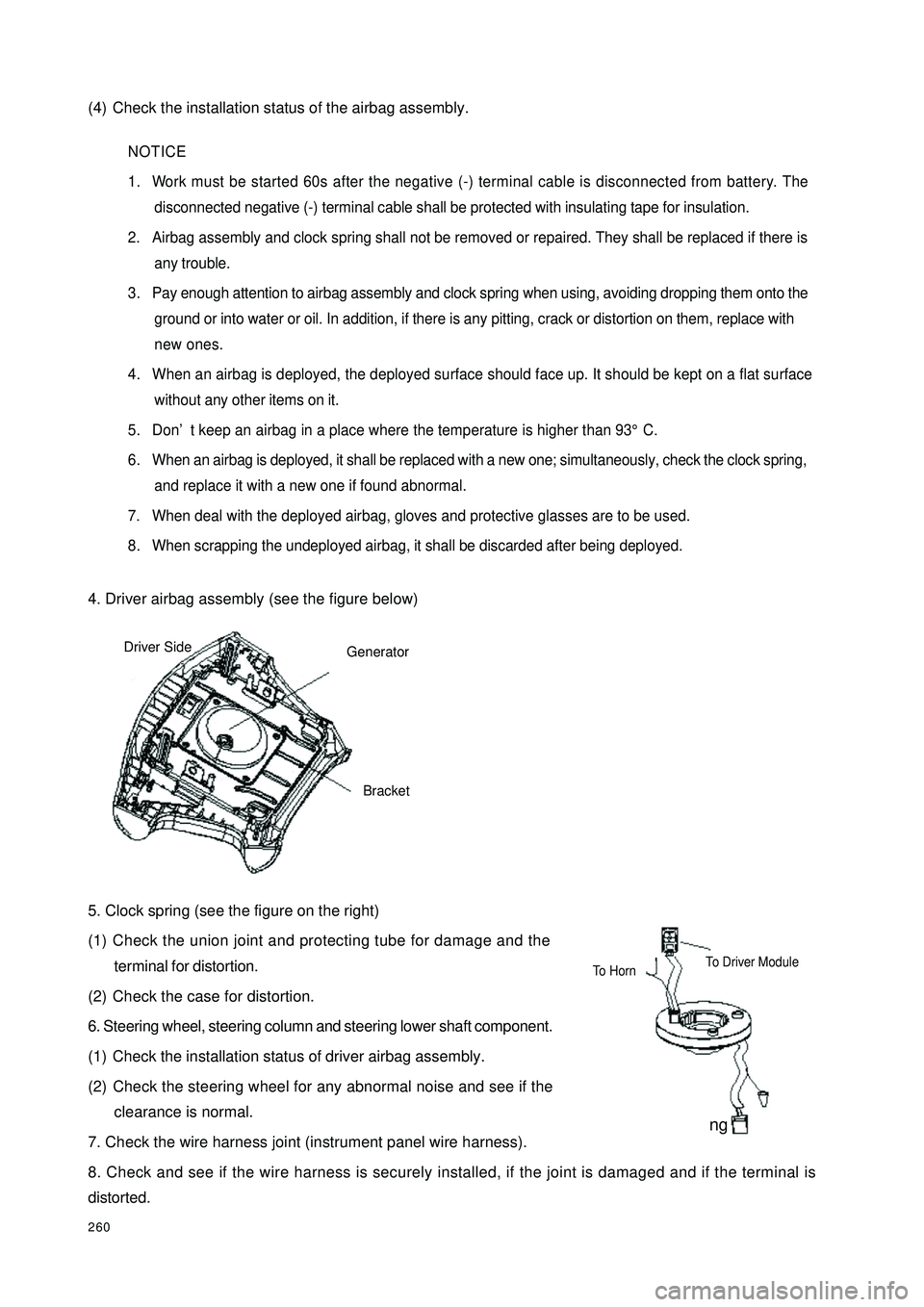
4. Driver airbag assembly (see the figure below)
5. Clock spring (see the figure on the right)
(1) Check the union joint and protecting tube for damage and the
terminal for distortion.
(2) Check the case for distortion.
6. Steering wheel, steering column and steering lower shaft component.
(1) Check the installation status of driver airbag assembly.
(2) Check the steering wheel for any abnormal noise and see if the
clearance is normal.
7. Check the wire harness joint (instrument panel wire harness).
8. Check and see if the wire harness is securely installed, if the joint is damaged and if the terminal is
distorted.NOTICE
1. Work must be started 60s after the negative (-) terminal cable is disconnected from battery. The
disconnected negative (-) terminal cable shall be protected with insulating tape for insulation.
2. Airbag assembly and clock spring shall not be removed or repaired. They shall be replaced if there is
any trouble.
3. Pay enough attention to airbag assembly and clock spring when using, avoiding dropping them onto the
ground or into water or oil. In addition, if there is any pitting, crack or distortion on them, replace with
new ones.
4. When an airbag is deployed, the deployed surface should face up. It should be kept on a flat surface
without any other items on it.
5. Don’t keep an airbag in a place where the temperature is higher than 93°C.
6. When an airbag is deployed, it shall be replaced with a new one; simultaneously, check the clock spring,
and replace it with a new one if found abnormal.
7. When deal with the deployed airbag, gloves and protective glasses are to be used.
8. When scrapping the undeployed airbag, it shall be discarded after being deployed.GeneratorBracketDriver Side Clock SpringTo HornTo Driver Module
Page 268 of 392
261IV. WARNING MARKSWhen using or maintaining an airbag, the warnings shall be indicated. When maintaining, proceed in accor-
dance with the description of mark. In addition, if the mark is damaged or stained, it shall be replaced.
1. Driver airbag assembly, see Fig. 1.
2. Clock spring, see Fig. 2.
3. ECU, see Fig. 3.
4. Sun Visor, see Fig. 4.
5. Steering wheel, Fig. 5.Warning MarkFigure 1Warning
MarkFigure 2Warning Mark
Figure 3Warning Mark Warning MarkFigure 4 Sun VisorFigure 5
Page 269 of 392

262Section 3 Removal & InstallationI. SRS ELECTRONICAL CONTROL UNIT (ECU)1. Operations prior to Removal
(1) Turn the ignition switch OFF.
(2) Remove negative (-) terminal cable of the battery. Put it in a proper position or wrap it up with insulating
tape.
2. Removal procedures:
(1) Remove the central passage side cover plate (or remove auxiliary console).
(2) Remove the connectors to SRS ECU.
(3) Remove ECU.
3. Installation procedures:
(1) Install ECU.
(2) Install the connectors to SRS ECU.
(3) Install the central passage side cover plate (or install auxiliary console).
(4) Connect negative (-) terminal cable of the battery.
4. Key points for Installation:
(1) Install ECU.
(2) Check after installation.
1Turn the ignition switch ON.
2The warning light goes on within 6s, and then goes out.
(3) If the light doesn't go out, check the trouble and eliminate it.NOTICE1. Work must be started 60s after the negative (-) terminal cable is detached from battery. The detachednegative (-) terminal cable shall be protected with insulating tape for insulation.
2. Never attempt to dismantle or repair an ECU. If there is any trouble, replace the ECU with a new one.
3. Prevent the ECU from shock or vibration. If pitting, crack or distortion is found, replace the ECU with
a new one.
4. Every time an airbag is deployed, the ECU shall be replaced with a new one.
5. When disassembling or maintaining the parts around ECU, attention must be given to avoid contacting
the ECU.NOTICE
If the ECU cannot be installed correctly, the airbag will not act normally.
Page 270 of 392

2635. Check:
1 ECU case for pitting, crack and distortion.
2 The joint for damage and distortion.
For other ECU checkings, see Troubleshooting.II. AIRBAG ASSEMBLY & CLOCK SPRING1. Operations prior to removal
(1) Take out the ignition key after the steering wheel and front wheel are adjusted to straightforward direction.
(2) Remove negative (-) terminal cable from the battery.
2. Removal procedures of the driver airbag assembly:
(1) Unscrew the screws of the two sides.
(2) Disconnect the connector of the wire harness.
(3) Remove the components of airbag assembly.
(4) Remove steering wheel.
3. Removal procedures of clock spring:
(1) Remove the driver airbag assembly (disconnect the connector).
(2) Remove steering wheel gently (see the precautions).
(3) Open the upper closure of the combination switch, locate and
disconnect the connector of wire harness in the lower end.
(4) Remove clock spring from the steering wheel.
4. Installation procedures of the driver airbag assembly
(1) Pre-Check
ySteering wheel
yConnect the wire harness
yDriver airbag assembly
(2) Screw up the installation screws of the two sides.
(3) Connection of the negative (-) terminal of the battery
(4) Check after installation.NOTICE
If pitting, crack or distortion is found on an ECU, replace it with a new one.NOTICE
Put the removed driver airbag
assembly upside down in a clean
and dry place for care.NOTICE
Put the removed clock spring in
a clean and dry place for care.
Page 271 of 392