Page 65 of 392
5811. Using the dial gauge, check the flywheel runout. See
(Figure 136).
The maximum runout: 0.3mm
12. Check clutch release bearing
The bearing is permanently lubricated. There is no need to
lubricate or clean.
13. Check clutch plate
14. Install clutch cover. See (Figure 137)
Align the Clutch cover to the mark on the flywheel.
Hint:
(1) Uniformly tighten the bolt in the sequence shown.
Torque: 19 N. m
(2) Shake the clutch plate up and down, left and right to ensure
it is centered, then tighten the bolt.
15. Check and adjust the clutch cover. See (Figure 138)
Check the diaphragm tip flatness with the dial gauge with roller.
Max. roughness: 0.5mm.
16. Install the release fork pivot pin
17. Install clutch release fork boot
18. Install clutch release bearing fixed clamp
19. Install clutch release fork
20. Install clutch release bearing
21. Install manual transaxle assemblyFigure 136
Figure 137
Figure 138
Page 66 of 392
59Chapter 8 Maunal Transaxle Assembly
(MR7131A, MR7151A, MR7161A)Component 1Figure 139
Page 67 of 392

60Section 1 Manual Transaxle Replacement1. Open the engine hood
2. Remove the battery
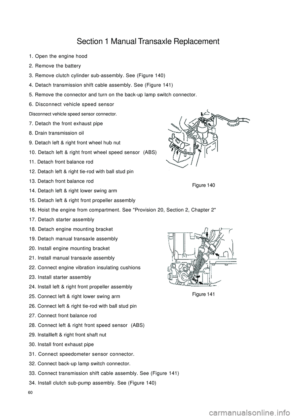
3. Remove clutch cylinder sub-assembly. See (Figure 140)
4. Detach transmission shift cable assembly. See (Figure 141)
5. Remove the connector and turn on the back-up lamp switch connector.
6. Disconnect vehicle speed sensor
Disconnect vehicle speed sensor connector.
7. Detach the front exhaust pipe
8. Drain transmission oil
9. Detach left & right front wheel hub nut
10. Detach left & right front wheel speed sensor (ABS)
11. Detach front balance rod
12. Detach left & right tie-rod with ball stud pin
13. Detach front balance rod
14. Detach left & right lower swing arm
15. Detach left & right front propeller assembly
16. Hoist the engine from compartment. See "Provision 20, Section 2, Chapter 2"
17. Detach starter assembly
18. Detach engine mounting bracket
19. Detach manual transaxle assembly
20. Install engine mounting bracket
21. Install manual transaxle assembly
22. Connect engine vibration insulating cushions
23. Install starter assembly
24. Install left & right front propeller assembly
25. Connect left & right lower swing arm
26. Connect left & right tie-rod with ball stud pin
27. Connect front balance rod
28. Connect left & right front speed sensor (ABS)
29. Installleft & right front shaft nut
30. Install front exhaust pipe
31. Connect speedometer sensor connector.
32. Connect back-up lamp switch connector.
33. Connect transmission shift cable assembly. See (Figure 141)
34. Install clutch sub-pump assembly. See (Figure 140)Figure 140
Figure 141
Page 68 of 392
61Section 2 Vehicle Speed Sensor Replacement1. Disconnect vehicle speed sensor. See (Figure 142)
2. Remove bolt and vehicle speed sensor.
3. Install vehicle speed sensor. See (Figure 142)
4. Connect vehicle speed sensor connector. See (Figure 143)
Figure 142 Figure 143
Page 69 of 392
62Section 3 Transmission Case Oil Seal1. Remove transmission case oil seal. See (Figure 144)
2. Install transmission case oil seal. See (Figure 145)
Notice:
Be careful not to damage oil seal lip.
Figure 144 Figure 145
Page 70 of 392
63Section 4 Transaxle Case Oil Seal Replacement1. Using special tool, remove transaxle case oil seal. See (Figure 146)
2. Install transaxle case oil seal. See (Figure 147)
Figure 144 Figure 145
Page 71 of 392

64Chapter 9 General Engine Troubles and Their
TroubleshootingSection 1 Overview The wide application of the electronic technologies to the vehicles brings innovation on diagnosis of the
vehicle, many varieties of diagnosis instruments that are very effective and efficient for the vehicle diagnosis
are innovated. Once the fault occurs, the best choice is to go to service station for help. However, even the
most advanced instrument has its limit. For some faults, manual diagnosis is far more convenient and easier
than that of instrument. In case of the crack, distortion and leakage of the components, the manual diagnosis
is even superior to the instrument diagnosis. The faults occurred shall be carefully analyzed and troubleshot
in accordance with the repair manual for normal usage.Section 2 General Engine Fault and TroubleshootingI. Fuel pipeline and circuit fault causing the engine starting failureengine starting failure normally include: starter does not run or starter runs but fails to crank the engine, or
cranks the engine but cranks slowly; starter can crank but fail to start the engine. There are many causes that
result in starting failure, such as failures in starting system, ignition system, fuel injection system and engine
mechanical failure.
1. starter does not run or fails to crank the engine or cranks slowly
(1) Symptom: starter does not run or spongy rotation
(2) Causes:
b. Low battery voltage, excessive battery discharge, damaged generator or failure in charging circuit;
c. Battery terminal rust and backed out;
d. Failure in starting circuit, ECU can not receive STA signal;
e. Damaged starter.
2. engine can not start and crank
(1) Symptom
With the start switch on, starter can crank but fail to start the engine.
(2) Causes
a. Empty fuel tank;
b. Electrical fuel pump inoperative;
c. Injector inoperative;
d. Low fuel pressure;
e. Unreasonable starting operation;
f. Damaged throttle position sensor or no signal is sent to ECU due to the open in throttle position
sensor circuit;
Page 72 of 392

65g. Ignition system failure;
h. Low engine compression pressure.
(3) Diagnosis and Troubleshooting
a. First, check the fuel tank for fuel level, turn on the ignition switch, if fuel gauge pointer does not
move or fuel level warning lamp lights, then the fuel tank is empty, fuel shall be filled at this time.
b. Check that the electrical fuel pump for operation. Remove the fuel tank, you may use a wire to
connect the two jacks of the fuel pump for short, then turn on the ignition switch. The fuel pump
operation sound shall be able to be heard from the fuel tank nozzle or fuel flow can be felt with hand
pinching the tube; or remove the return hose on the fuel pressure regulator, check that the fuel
flows out; Direct judgment can be made if it is equipped with fuel pressure gage.
If electrical fuel pump is inoperative, check whether the main fuse, main relay, fuel pump relay,
fuel pump control circuit and ECU are OK. If all of them are OK, check fuel pump circuit for open,
short or damaged check valve. Repair or replacement shall be made when problems are found.
c. If there is no injection sound in injector, check injector control circuit for fault. You may use a
testing lamp with big resistance to be connected to the injector wiring connector, turn on the ignition
switch. If the testing lamp lights up, it indicates that the injector has been damaged and shall be
replaced; if the testing lamp does not light up, check whether the main fuse, EFI relay, fuse, ignition
switch and ECU terminal are OK, repair or replace them if they are not OK.
d. If there is low fuel pressure, the injection amount would be small and the engine won't start, you
should check the fuel filter for block and fuel pump safety valve for damage and check whether the
fuel pressure regulator is within the normal range, otherwise those components shall be repaired or
replaced.
e. Electric injection engine normally spot contact start the engine.
f. Check for open in the throttle position sensor (TPS) circuit.
g. Check whether there is Diagnostic Trouble Code (DTC), if there is, check it by the DTC; if there
is not, check the high voltage spark for intensity, if it is too weak, check spark plug, high voltage
wire, high voltage coil, distributor cover for faults, if there are faults, repair or replace them.
h. Check the compression pressure in the cylinder, insert the compression pressure gauge into the
spark plug hole, completely open the throttle, measure the compression pressure while starting the
engine. If the compression pressure is less than 980kPa when engine speed is more than 250r/min,
remove and inspect the engine and troubleshoot it.
3. The engine cranks but can not start
(1) Symptom
When starting the engine, starter can crank the engine but fail to start the engine.
(2) Causes:
a. Ignition advance angle is unfavorable;
b. Ignition is out of sequence, there is misfire;
c. High voltage spark is too weak;
d. The fuel pressure is too low;
e. fuel pressure regulator leakage;