Page 89 of 392

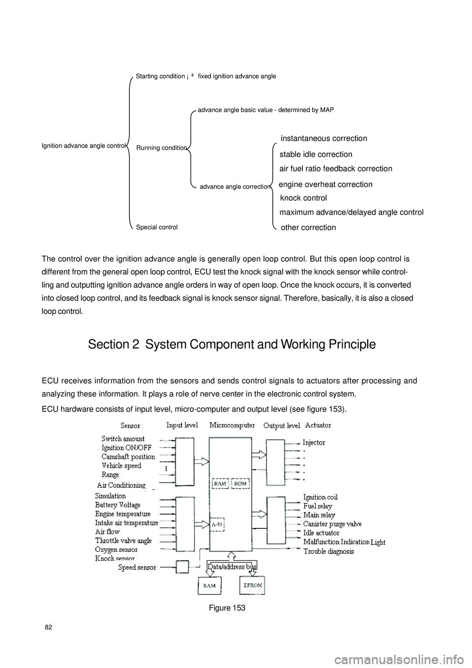
82The control over the ignition advance angle is generally open loop control. But this open loop control is
different from the general open loop control, ECU test the knock signal with the knock sensor while control-
ling and outputting ignition advance angle orders in way of open loop. Once the knock occurs, it is converted
into closed loop control, and its feedback signal is knock sensor signal. Therefore, basically, it is also a closed
loop control.Section 2 System Component and Working PrincipleECU receives information from the sensors and sends control signals to actuators after processing and
analyzing these information. It plays a role of nerve center in the electronic control system.
ECU hardware consists of input level, micro-computer and output level (see figure 153).
Figure 153Ignition advance angle control Starting condition ¡ª fixed ignition advance angle
Running conditionSpecial controladvance angle basic value - determined by MAPadvance angle correctioninstantaneous correction
stable idle correction
air fuel ratio feedback correction
engine overheat correction
knock control
maximum advance/delayed angle controlother correction
Page 90 of 392

83ECU microcomputer consists of microprocessor, memory, clock generator, timer, I/O interface and input
level A/D converter that are integrated in a large scale integrated circuit chip, that is SCM (Single Chip
Microcomputer).
1. Input level
The input signals from the sensor are pre-processed by the input level. The input signals are sent to protected
circuit first, sometimes through the signal converter and amplifier, and then sent to microcomputer.
The sensor signal is separated into switch type and analog type. Ignition on/off signal, camshaft position
signal, vehicle speed signal and A/C signal are switch type; Signals such as battery voltage, engine temperature,
intake temperature, airflow, intake manifold absolute pressure, throttle opening, excessive air coefficient,
knock, A/C refrigerant pressure are analog type. Analogy signal can only be processed by the digital micro-
computer after being converted into digital signal by A/D converter. Hence, data collection shall be made
first for analog signal, and the sampling shall be maintained also.
Speed and crankshaft position reference signal from the sensor is processed in a dedicated circuit to restrain
the interference pulse.
2. Microcomputer
The microcomputer of the engine electronic control unit is integrated in a single chip microcomputer, consist-
ing of the following:
(1) Microprocessor, microprocessor is also called as central processing unit (CPU), consisting of the following
three parts:
Arithmetic logic unit.
Register group.
Controller.
(2) System assembly, The data transferred among the internal sections of the single chip microcomputer
(SCM) is performed on the internal bus, while that between the SCM and other components is performed
on the external bus. The external bus is also called system bus. It is separated into data bus, address bus
and control bus.
(3) Memory, the memory is designed to store the binary data. The primary components of the memory are:
Memory.
Data register.
Address register, address decoder.
a. Memory controller
(4) A/D converter
(5) I/O interface.
(6) Clock generator.
(7) Timer
(8) CAPCOM unit.
(9) Watchdog timer.
(10) Interrupt system.
Page 91 of 392

843. Output Level
ECU output level is designed to send control signal to the actuators of the electronic control system based on
the orders of the microprocessor in the micro-controller. The microprocessor control the output level by
controlling the occurrence position of the pulse, its length and duty ratio.
(1) Injection output level
The microprocessor controls the pulse length of the injection output level by making sure whether to
trigger to circuit or not in the injection output level.
(2) Ignition input level
The ignition output level is designed to amplify the ignition signal from the microprocessor into the primary
current of the ignition coil.
(3) Electric fuel pump output level
ECU microcontroller control the pump relay through electric fuel pump output level, and then control the
on and off of the electric fuel pump based on the current operating conditions.
(4) Other output levels
Control the output levels of the idle control valve, carbon canister solenoid valve, malfunction indicator
lamp. MR479Q, MR479QA, MR481QA engine idle control are closed loop control system, their injection
and ignition control are also closed loop control system.
Page 92 of 392

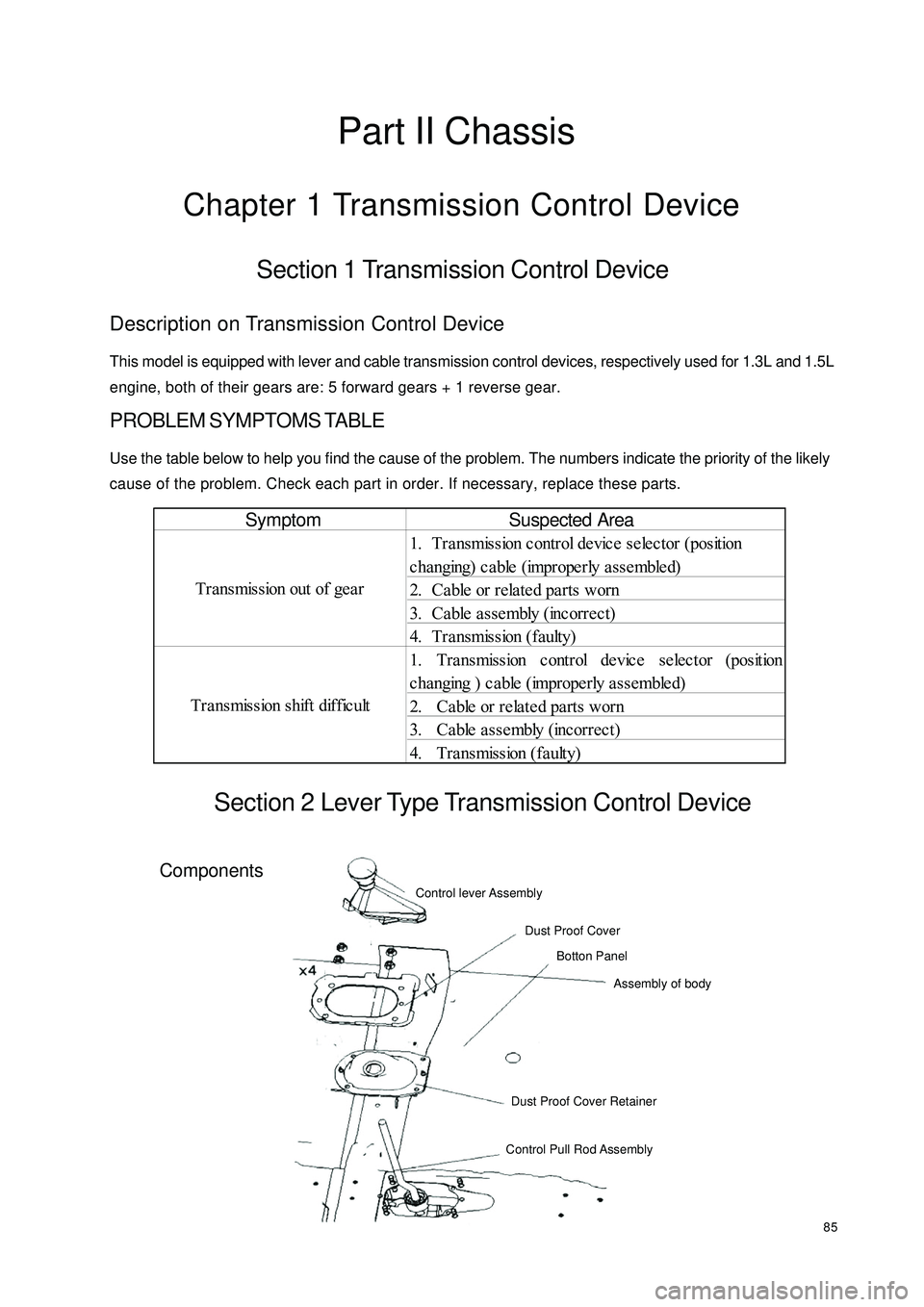
85Part II ChassisChapter 1 Transmission Control DeviceSection 1 Transmission Control DeviceDescription on Transmission Control DeviceThis model is equipped with lever and cable transmission control devices, respectively used for 1.3L and 1.5L
engine, both of their gears are: 5 forward gears + 1 reverse gear.PROBLEM SYMPTOMS TABLEUse the table below to help you find the cause of the problem. The numbers indicate the priority of the likely
cause of the problem. Check each part in order. If necessary, replace these parts.Section 2 Lever Type Transmission Control DeviceComponentsSymptom
1. Tra nsmission c ontrol de vic e se le ctor (position
changing) cable (improperly assembled)
2. Ca ble or rela te d pa rts worn
3. Ca ble a sse mbly (incorrec t)
4. T r a ns mis s ion ( f a ult y)
1. Transmission control device selector (position
changing ) cable (improperly assembled)
2. Ca ble or rela te d pa rts worn
3. Ca ble a sse mbly (incorrec t)
4. Transmission (faulty) Transmission out of gea r
Transmission shift difficultControl lever Assembly
Dust Proof Cover
Botton Panel
Assembly of body
Dust Proof Cover Retainer
Control Pull Rod AssemblySuspected Area
Page 93 of 392
86Replacement1. Remove shift lever assembly
(1) Pull upwards to separate the shift lever assembly leather boot from the auxiliary console
(2) Loosen the shift lever set screw with inner hex wrench. Remove the shift lever assembly counterclockwise
2. Remove auxiliary console
3. Remove control lever dust cover
Remove the 4 nuts on the control lever dust cover and the body.
4. Remove dust cover retainer
5. Remove control pull rod assembly
(1) Remove the pull rod connecting bolt (Place 2)
(2) Remove 2 hex flange bolts (Place 1)
(3) Remove the 2 flange nuts attaching the control pull rod to the body in the trench
6. The installation is in the reverse order of the above operation.
Notice:
(1) Pull rod (to transmission) attach bolt torque: 40~50N.m
(2) The torque of the two nuts attaching the control mechanism to the body: 20~25N.mBottom Panel
Assembly of
BodyControl Pull Rod Assembly
Transmission Assembly
Page 94 of 392
87(3) Dust cover retainer shall be assembled well, otherwise the dust seal effect will be af-
fected
(4) Dust cover fixing nut torque: 20~25N.m
(5) Make sure the shift number words on the top of shift lever ball face towards the driving
direction of the vehicle, properly tighten the set screw of the shift lever
(6) Check whether the shift control is flexible and reliable; the shift lever shall be vertical
when in neutral shift.Section 3 Cable Type Transmission Control ModuleComponentsShift Lever AssemblyE Shaped
clip plateCotter PinBig Washer Big Washer Cotter PinE Shaped clip plateTransmission
AssemblyCowl BaffleShift Control DeviceCushionBottom Panel
Assembly of Body
Page 95 of 392
88Replacement1. Remove shift lever assembly
(1) Pull upwards to separate shift lever assembly leather boot from the auxiliary console
(2) Loosen shift lever set screw with inner hex wrench. Remove the shift lever assembly counterclockwise.
2. Remove the auxiliary console
3. Remove the 4 nuts connecting manual shift assembly and the floor
4. Remove the shift cushion
5. Remove transmission control device assembly
(1) Remove the set nut on the cable seal press plate
(2) Remove the cotter pin and the flat washer connecting the cable and the rocker arm on the transmission
(3) Remove the E-shaped clip plate on the cable bracket retaining the cableShift Control
CablesE Shaped
Clip PlateBall SeatShift Lever Assembly LeverBall PinSpindle IISpindle IE Shaped
Clip PlateWave WasherBushBushSpring BushBall Pin Seat Torsion Spring Support
Plate Bottom BracketConjuction
Frame
Page 96 of 392

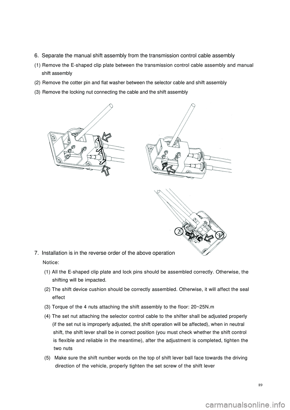
896. Separate the manual shift assembly from the transmission control cable assembly
(1) Remove the E-shaped clip plate between the transmission control cable assembly and manual
shift assembly
(2) Remove the cotter pin and flat washer between the selector cable and shift assembly
(3) Remove the locking nut connecting the cable and the shift assembly
7. Installation is in the reverse order of the above operation
Notice:
(1) All the E-shaped clip plate and lock pins should be assembled correctly. Otherwise, the
shifting will be impacted.
(2) The shift device cushion should be correctly assembled. Otherwise, it will affect the seal
effect
(3) Torque of the 4 nuts attaching the shift assembly to the floor: 20~25N.m
(4) The set nut attaching the selector control cable to the shifter shall be adjusted properly
(if the set nut is improperly adjusted, the shift operation will be affected), when in neutral
shift, the shift lever shall be in correct position (you must check whether the shift control
is flexible and reliable in the meantime), after the adjustment is completed, tighten the
two nuts
(5) Make sure the shift number words on the top of shift lever ball face towards the driving
direction of the vehicle, properly tighten the set screw of the shift lever