Page 369 of 392

362(II) Floor AssemblyFloor assembly is the base of the main body and an important structure component to link with assemblies
and for load transfer and bearing. The vehicle running performance depends on its intensity and rigidity.
Figure 5-3 is the dismantle diagram of the floor parts.
Floor assembly is composed of front floor assembly and rear floor assembly. A protrusile tunnel runs longitu-
dinally in the center of the front floor. The tunnel and the lower floor rail can strengthen its rigidity in
longitudinal direction. The lower space of the tunnel is used to mount components such as transmission shift
pull rod, park brake drawing cable, exhaust pipes with 3-way catalytic converter. Carpet and sound insulator
mat are mounted in the inner side of the compartment. The first and the second cross member, LH/RH side
member and side rails which are on the front floor form a frame structure. It can provide great load-bearing
capacity to assure strict running requirements for body.
Figure 5-3 Decomposition Diagram of Floor Parts
1 LH/RH Front Floor Side Rail 2 Front Floor 3 Front Floor Cross Member 4 LH/RH Floor Side
Member 5 Rear Floor 1st Cross Member 6 LH/RH Rear Floor Side Rail 7 Rear Floor 2nd Cross
Member Assy. 8 Rear Floor2143456 678Front
Page 370 of 392
363 (III) Side Wall AssemblyLH/RH side wall assembly is frame structure. It is mainly composed of parts such as LH/RH front pillar sub-
assembly, LH/RH central pillar reinforcement, LH/RH upper side rail, LH/RH floor side rail outer panel, LH/
RH side wall inner/outer panel...etc., by welding them together. Figure 5-4 is the dismantle diagram.
Figure 5-4 Decomposition Diagram of Quarter Parts
1. LH/RH Front Pillar Inner Plate 2 LH/RH Upper Side Member Front Inner Plate 3 LH/RH Front
Pillar Outer Plate Reinforcement 4 LH/RH Upper Side Member Inner Plate Assy.
5.LH/RH Doorframe Lower Side Member Outer Plate Reinforcement 6 LH/RH Central Pil-
lar Outer Plate Reinforcement 7 LH/RH Rear Wheel House Inner Plate Sub-assy 8 LH/RH Rear
Wheel House Outer Plate Sub-assy 9 LH/RH Side Wall Outer Plate 157926485874293163 Front Left
Right
Page 371 of 392
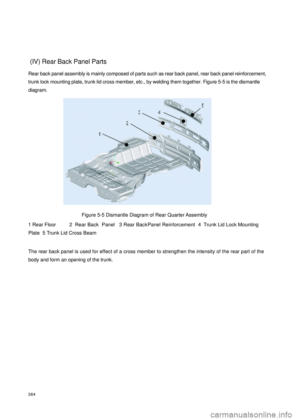
364 (IV) Rear Back Panel PartsRear back panel assembly is mainly composed of parts such as rear back panel, rear back panel reinforcement,
trunk lock mounting plate, trunk lid cross member, etc., by welding them together. Figure 5-5 is the dismantle
diagram.
Figure 5-5 Dismantle Diagram of Rear Quarter Assembly
1 Rear Floor 2 Rear Back Panel 3 Rear Back Panel Reinforcement 4 Trunk Lid Lock Mounting
Plate 5 Trunk Lid Cross Beam
The rear back panel is used for effect of a cross member to strengthen the intensity of the rear part of the
body and form an opening of the trunk. 12345
Page 372 of 392

365(V) Roof Panel AssemblyRoof panel assembly is mainly composed of parts such as roof panel, roof front cross member, roof central
reinforcement, roof rear cross member, etc., by welding them together. Shown as the dismantle diagram 5-
6.Roof interior trim is mounted inside; and an insulation mat is pasted in its interlayer. Cohesive binder is
applied between the front/central/rear cross member and the roof panel in many points. The rainwater from
the roof panel flows out of the rear body through roof drip channel that are on the both sides of the roof panel.
Cross members and reinforcement members are used to strengthen the rigidity of the roof panel in trans-
verse direction.
Figure 5-6 Decomposition Diagram of Roof
1 Roof Panel 2 Front Roof Cross Member 3 Roof Central Reinforcement
4 Rear Roof Cross Member(VI) Trunk Shelf AssemblyTrunk shelf assembly is mainly composed of parts such as trunk shelf panel, trunk shelf front reinforcement
plate, drip channel etc., by welding them together.
Trunk shelf is welded to the LH/RH quarter, which and rear floor, the back of the quarter form a trunk.
Meanwhile, a frame that can resist to torsion is also generated. Figure 5-7 is the dismantle diagram.
Figure 5-7 Decomposition Diagram of Floor Parts.
1 Trunk Shelf Reinforcement Plate 2 Trunk Shelf Panel 3 Drip Channel1234132
Page 373 of 392

366II. Removable Sheet Metal Parts
(I) Engine Hood, Front Fender1. Engine hood is mainly used to protect the engine, meet the whole vehicle design, and make the mainte-
nance convenient. It also has an effect of isolating the engine noise. The engine hood has a double-insurance
lock system. The release of the first lock is controlled by the drawing cable that is under the instrument panel.
As to the release of the second lock, you should firstly release the first one and the hood will open, and then
move the hood lock hook. The double-insurance lock system is designed for safety, especially in the course
of running with a high-speed, to prevent the engine hood from being raised, which often causes traffic
accidents. The angle of the hood that is fully opened is 52°.As shown in Figure 5-8
Figure 5-8 Engine Hood Hinge
1Hinge Bracket 2 Hinge Arm 3 Pin Shaft(II) Front FenderThe matching relationship between the front fender and hood, front door is as shown in the Figure 5-9.
Figure 5-9 Section Around The Front Fender
A) The matching relationship with the hood (5mm ± 0.5mm)
B) The matching relationship with the front door (5mm ± 0.5mm) 13252†while fully open
Engine Hood
outer plate
Engine Hood
inner plate
AEngine HoodFront fender
Front door
Front fender
B
Page 374 of 392

367(III) Door AssemblyThe door adopts limit hinges. The hinge is mounted on the front pillar of the door frame.
A door is mainly composed of the door outer and inner plate, anti-impact bar and door reinforcement plate.
The structure of the door is complicated, because it is a movable part. It is designed to form a sealed
compartment with the main body and relevant parts, and also convenient for drivers and passengers to get in
and out of the vehicle. And the devices on the door have to bear high-frequency operation. So it must meet
very high requirements in reliability and durability.
The inner and outer plates are both molded from a whole steel plate, which is for improving the rigidity and
assembly accuracy. In order to assure the safety when the vehicle is crashed on the side of the body; anti-
impact bar and central reinforcement plate are equipped in the door.
Door plate assembly is composed of the outer and inner sub-assemblies. Use a special folded edge machine
to wrap along the full circle of the door outer plate and the inner plate sub-assemblies to get them together.
As shown in Figure 5-10 & 5-11
Figure 5-10 Dismantle Diagram of Front Door Plate
1 Front Door Inner Plate2 Front Door Window Glass Rail 3 Front Door Inner Upper Rein-
forcement Plate 4 Front Door Inner Middle Reinforcement Plate 5 Front Door Upper Hinge
6 Front Door Lower Hinge 7 Front Door Hinge Reinforcement 8 Door Anti-impact Bar Assy.
9 Front Door Outer Plate123456798
Page 375 of 392
368Figure 5-11 Dismantle Diagram of Rear Door Plate
1 Rear Door Inner Plate2 Rear Door Window Glass Rail 3 Rear Door Inner Upper Reinforce-
ment Plate 4 Rear Door Inner Middle Reinforcement Plate 5 Rear Door Upper Hinge
6 Rear Door Lower Hinge 7 Rear Door Hinge Reinforcement 8 Door Anti-impact Bar Assy.
9 Rear Door Outer Plate(IV) Trunk Lid Welding AssemblyTrunk lid assembly is mainly composed of parts such as trunk lid outer plate, trunk lid inner plate, trunk lid
hinge mounting plate, trunk lid lock mounting plate, etc., by welding them together. As shown in Figure 5-12
Figure 5-12 Decomposition Diagram of Trunk Lid
1 Hinge Mounting Plate 2 Hinge Spring 3 Trunk Lid Hinge 4 Trunk Lid Inner Plate
5 Trunk Lid Lock Mounting Plate 6 Trunk Lid Outer Plate6237489151223645
Page 376 of 392
369Chapter 2 Body RepairSection 1 Body Damage Forms and Requirements for RepairI. Body Damage FormsThe body damage forms are deformation caused by crash, overload, fatigue and corrosion, and tearing,
rusting, water & dust leaking.
The damage of the body is caused not only by overload, also by being often in an abnormal operating status
when the door or other parts are damaged. However, at most times, accidents like crash and turnover result
in bending and torsioning deflection because of the great overload on partial areas.
General conditions of the body damage are as follows:
1. The Front Central Is Crashed (Figure 5-13)
Figure 5-13 The Front Central Is Crashed
Because the front central is damaged by outside force, the left and right hood is usually stretched inwards;
therefore, the following are the key places to inspect.
1Nearby the left and right mounting place of the hood;
2Nearby the left and right mounting connection place of the front cross member.