Page 200 of 392

193Chapter 4 Wiper and Washer SystemSection 1 Wiper and Washer System InspectionI.WIPER AND WASHER SYSTEM SYMPTOM ANALYSISNOTES:
The table below can help you find the causes of malfunction. These figures show the most possible malfunc-
tions in order of priority. Inspect each part in the order given. If necessary, repair or replace these parts.Symptom Suspected Area
1. Wipe r fuse
2. Wipe r switc h a sse mbly
3. Harne ss
1. Wipe r switc h a sse mbly
2. Wipe r motor a sse mbly
3. Harne ss
4. Ce ntra l controlle r
1. Wipe r fuse
2. Wipe r switc h a sse mbly
3. Wipe r motor a sse mbly
4. Harne ss
1. Wipe r switc h a sse mbly
2. Wipe r motor a sse mbly
3. Harne ss
4. Ce ntra l controlle r
Wa she r fluid dose not jet out 1. Wa she r hose a nd nozzleWhen the washer switch places on OFF, wiperbla de ca n not return, or sta y in a wrong pla ce .1.Wipe r motor a sse mbly (The position of wipe r a rm) Front wipe r doe s not operate .
Front wipe r in inte rmitte nt shift does not
operate.
Front wa she r motor doe s not operate
When the washer switch is placed ON, front
wipe r does not ope ra te
Page 201 of 392
194II. MALFUNCTION INSPECTION1. WASHER PUMP INSPECTION
(1) Mount washer pump on the can system. Pour washer fluid into the can.
(2) Disconnect the connector of washer pump.
(3) Connect the terminal 1 of washer pump to the battery positive (+) and the terminal 2 to the negative (-),
as shown below. Inspect that the washer fluid flows out of the can.
(4) If not, replace the washer pump.
2. WIPER SWITCH ASSEMBLY
(a) Inspect the continuity
�yInspect each terminal on connector for continuity.
Standard:Switch position Tested terminal Specified condition
MIST 8(
+)
—10(
+)
Continuity
OFF 3(
+)
—10(
+)
Continuity
INT 8(
+)
—6(
+)
3(
+)
—10(
+)
Continuity
LO 8(
+)
—10(
+)
Continuity
HI 8(
+)
—11(
-)
Continuity
Page 203 of 392

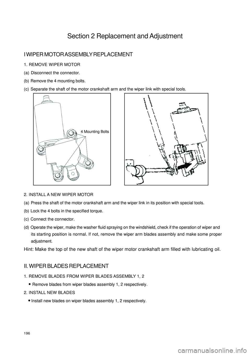
196Section 2 Replacement and AdjustmentI WIPER MOTOR ASSEMBLY REPLACEMENT1. REMOVE WIPER MOTOR
(a) Disconnect the connector.
(b) Remove the 4 mounting bolts.
(c) Separate the shaft of the motor crankshaft arm and the wiper link with special tools.
2. INSTALL A NEW WIPER MOTOR
(a) Press the shaft of the motor crankshaft arm and the wiper link in its position with special tools.
(b) Lock the 4 bolts in the specified torque.
(c) Connect the connector.
(d) Operate the wiper, make the washer fluid spraying on the windshield, check if the operation of wiper and
its starting position is normal. If not, remove the wiper arm blades assembly and make some proper
adjustment.
Hint: Make the top of the new shaft of the wiper motor crankshaft arm filled with lubricating oil.II. WIPER BLADES REPLACEMENT1. REMOVE BLADES FROM WIPER BLADES ASSEMBLY 1, 2
�yRemove blades from wiper blades assembly 1, 2 respectively.
2. INSTALL NEW BLADES
�yInstall new blades on wiper blades assembly 1, 2 respectively.4 Mounting Bolts
Page 204 of 392
197III. WIPER SWITCH ASSEMBLY REPLACEMENT1. DETACH STEERING WHEEL ASSEMBLY
(a) Disconnect the main power source of the vehicle.
(b) Remove the passenger SRS module assembly, and cautiously put it in a safe place.
(c) Loosen steering wheel lock-bolts and remove the assembly.
2. REMOVE WIPER SWITCH
(a) Disconnect the connector.
(b) Remove the 2 tapping screws that are for mounting the wiper switch, take out the wiper switch from the
bracket of the combination switch.IV. WASHER NOZZLEADJUSTMENT
1. INSPECT WASHER NOZZLE
(a) Start the engine, check if the position where the washer fluid from the nozzle sprays the windshield is in
the central or upper of the area wiped by the blades.
(b) Change the direction (horizontal) of the nozzle hole to adjust the point where washer fluid sprays the
windshield.