2008 GEELY CK battery replacement
[x] Cancel search: battery replacementPage 17 of 392

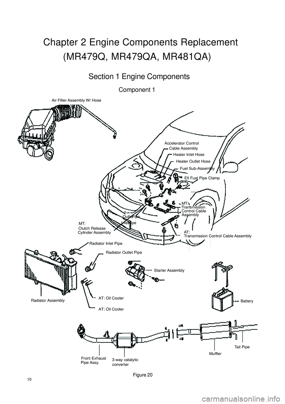
10Chapter 2 Engine Components Replacement
(MR479Q, MR479QA, MR481QA)Section 1 Engine ComponentsComponent 1Air Filter Assembly W/ Hose
Accelerator Control
Cable Assembly
Heater Inlet Hose
Heater Outlet Hose
Fuel Sub-Assembly
Efi Fuel Pipe Clamp
MT:
Transmission
Control Cable
Assembly
AT :
Transmission Control Cable Assembly MT:
Clutch Release
Cylinder Assembly
Radiator Outlet Pipe Radiator Inlet Pipe
Starter AssemblyAT: Oil Cooler Outlet Pipe
AT: Oil Cooler Inlet Pipe
Radiator Assembly
BatteryFront Exhaust
Pipe Assy.3-way catalytic
converterMufflerTail PipeFigure 20
Page 20 of 392

13Section 2 Engine Components Replacement1. Avoid gasoline ejection when work.
2. Drain the coolant to empty.
3. Remove air filter assembly with hose. See (Figure 23)
4. Remove battery
5. Remove fuel delivery pipe sub-assembly
6. Disconnect water hoses, disconnect heater outlet hose
from A/C hose.
7. Loose nut, remove accelerator control cable
8. Remove throttle body assembly
9. Remove power steering pump reservoir assembly
10. Remove front exhaust pipe assembly
11. Remove steering gear boot
12. Seperate steering column assembly. See (Figure 24)
13. Remove front wheel hub nut
14. Disconnect front wheel vehicle speed sensor (with ABS)
15. Detach steering tie rod ball stud pin assembly
16. Detach front lower swing arm sub-assembly
17. Detach front propeller assembly. See (Figure 25)
Detach front propeller from the shaft hub with plastic hammer.
18. Disconnect transmission shift cable or gear shift level assembly
19. Disconnect clutch cylinder assembly or disconnect clutch cable
20. Detach engine assembly and transaxle
(a) Hoisting engine ;
(b) Remove 3 bolts. Detach the right engine mounting bracket. See (Figure 26) ;
(c) Remove 1 bolt. Detach the left engine mounting bracket;
(d) Remove 1 bolt. Detach the rear engine mounting bracket;
(e) Remove engine and transaxle and put them on the pallet;
(f) Jack up the boday.Figure 23
Figure 24
Figure 25 Figure 26
Page 38 of 392

31Replacement1. Disconnect all the wire harnesses and the cables on the engine connected to the car body.
2. Detach air filter assembly with hose
3. Disconnect oil pipe and water hose
4. Loose positive and negative cables of the battery.
5. Detach propeller shaft. Detach front exhaust pipe assembly
6. Loose engine left & right rear brackets after hoisting the engine.
7. Disconnect all the other connectors between the engine and the car body.
8. See "Provision 20, Section 2, Chapter 2". Lift the car body and take out the engine assembly.
9. Remove A/C compressor to the crankshaft pulleyV-belt.
10. Remove power steering pump V-belt.
11. Detach water pump fan pulley.
12. Disconnect ignition coil and high voltage cable.
13. Detach cylinder head cover sub-assembly.
14. Detach generator assembly.
15. Detach the camshaft.
16. Detach the throttle body assembly
17. Detach intake manifold stay No. 2.
18. Take out the dipstick
19. Detach No. 1 fuel delivery pipe
20. Detach the wire harness.
21. Detach the steering assisting pump assembly
22. Detach exhaust manifold. See (Figure 71)
23. Pry cylinder head from the dowel pin on the cylinder block.
See (Figure 72)
24. Remove the cylinder head gasket.
25. Install cylinder head gasket
26. Install cylinder head sub-assembly
27. Install exhaust pipe assembly.
(a) Install the new gasket and exhaust manifold with 5
bolts. Torque: 34N. m
(b) Install exhaust manifold stay with 2 bolts.
(c) Install upper heat shield with 4 bolts
Torque: 17N. mFigure 71
Figure 72
Page 67 of 392

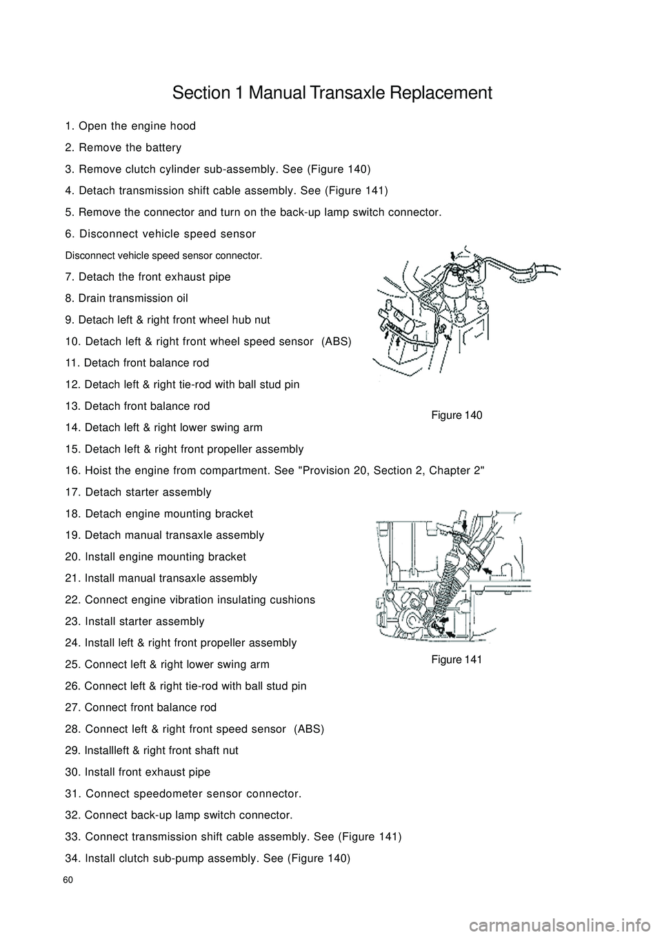
60Section 1 Manual Transaxle Replacement1. Open the engine hood
2. Remove the battery
3. Remove clutch cylinder sub-assembly. See (Figure 140)
4. Detach transmission shift cable assembly. See (Figure 141)
5. Remove the connector and turn on the back-up lamp switch connector.
6. Disconnect vehicle speed sensor
Disconnect vehicle speed sensor connector.
7. Detach the front exhaust pipe
8. Drain transmission oil
9. Detach left & right front wheel hub nut
10. Detach left & right front wheel speed sensor (ABS)
11. Detach front balance rod
12. Detach left & right tie-rod with ball stud pin
13. Detach front balance rod
14. Detach left & right lower swing arm
15. Detach left & right front propeller assembly
16. Hoist the engine from compartment. See "Provision 20, Section 2, Chapter 2"
17. Detach starter assembly
18. Detach engine mounting bracket
19. Detach manual transaxle assembly
20. Install engine mounting bracket
21. Install manual transaxle assembly
22. Connect engine vibration insulating cushions
23. Install starter assembly
24. Install left & right front propeller assembly
25. Connect left & right lower swing arm
26. Connect left & right tie-rod with ball stud pin
27. Connect front balance rod
28. Connect left & right front speed sensor (ABS)
29. Installleft & right front shaft nut
30. Install front exhaust pipe
31. Connect speedometer sensor connector.
32. Connect back-up lamp switch connector.
33. Connect transmission shift cable assembly. See (Figure 141)
34. Install clutch sub-pump assembly. See (Figure 140)Figure 140
Figure 141
Page 73 of 392

66f. The idle control valve is faulty;
g. The water temperature sensor is damaged;
h. The vacuum pressure sensor is damaged;
i. The air filter is blocked;
j. The injector leaks;
k. The compression pressure in the cylinder is too low;
l. The intake temperature sensor is damaged.
(3) Diagnosis and Troubleshooting
a. Check high pressure spark, check whether the high pressure spark on the ignition coil high pressure
bus and extension are OK, if the bus spark is week, replace the ignition coil, if the bus spark is OK
while the extension spark is too week, replace the ignition coil also; In addition, excessive spark
plug clearance will influence the starting feature, the clearance of the spark plug shall be adjusted
to normal value (0.8±0.1mm);
b. If there is low fuel pressure, check whether the battery voltage is OK, otherwise it shall be
troubleshot or replaced; check fuel pump check valve for leakage, check fuel filter and fuel pipe for
block, if there are leakage or block, replace or troubleshoot them;
c. If there is leakage for fuel pressure regulator, intake manifold is likely to be mixed with gasoline and
it is hard to start, troubleshoot or replace them;
d. Idle control valve can not be opened to maximum position due to mechanical wear, aging or control
circuit failure, the idle control valve shall be replaced and the control circuit failure shall be troubleshot;
e. If the water temperature sensor data is not accurate, it may cause small injection, check the water
temperature sensor based on the standard data and calibrate the data;
f. There is big time lag for intake pressure temperature sensor that makes it somewhat insensitive at
low speed and result in inaccurate injection, adjustment or replacement shall be made;
g. If the air cleaner filter is too dirty, the air flow resistance is excessively big, resulting in hard start,
as a result of it, the filter shall be replaced.
In a word, there are many factors causing the starting failure of the engine, analysis shall be made based on
the severe conditions of the faults. Generally speaking, check the ignition system first, then check intake
system, fuel system, control system, at last check the cylinder pressure, check the DTC before checking the
trouble. The diagnosis and troubleshooting procedures for starting failure of the engine are shown in (Figure
148).
Page 138 of 392

131Replacement1. Cautions (refer to Steering System Cautions)
2. Make sure the wheels are placed straight ahead
3. disconnect the battery negative terminals
4. Remove the air bag assembly
Remove two screws on both sides and pull out the wiring harness connector
Notice: Do not pull air bag wire harness when removing the air bag assembly!
Warning:
�‹ �‹�‹ �‹
�‹Make sure the upper surface of the air bag assembly is kept upward when placing it!
�‹ �‹�‹ �‹
�‹Do not disassemble the air bag assembly!
5. Remove steering wheel assembly
(1) Remove the nut.
(2) Remove the steering wheel cover set bolt.
(3) place the matchmarks on the steering wheel and main shaft assembly.
(4) Use special tool to remove the steering wheel assembly.
6. Remove the steering column upper and lower cover
(1) Remove 3 screws.
(2) Remove the steering column upper and lower cover.Use Inner
Hex Socket
Wrench
Page 245 of 392

238Section 4 Audio and Video System ReplacementI. Notice on operationPlease explain to the customer that the AM/FM broadcast channel information will be cleared when remov-
ing the battery negative terminal cable. Record the channel information before removing the negative termi-
nal cable if necessary. Reset after connecting the negative terminal cable.
�yAll cassette tapes and CDs must be taken out before radio removal and installation.
�yIf the cassette tapes and CDs can not be taken out due to radio fault. Do not take them out by force.
Drive the vehicle to Service Station.
�yMake sure the grounding bolts are tightened before antenna removal and installation.
�yThere will be noise when receiving electric wave if the grounding bolts are not tightened.
�yDon't touch the speaker cone.Intermediate Multiple CD main unit Radio assemblyInstrument PanelMultiple DVD main unit
Page 333 of 392

326(III) Outside Rear View MirrorAttach the outside rear view mirror to the left and right doors. Integrate the outside rear view mirror with the
body smoothly using specially designed rubber bushing to make it a whole. The forward and rearward folding
of the rear view mirror will not be affected after being knocked. It is also a major way to reduce the whole
vehicle's air resistance coefficient.
Attach the lens to the plate with double sided adhesive tape. The plate is connected to the rear view mirror
case with the ball hinge to prevent fragment from splashing when it is broken, which may result in injury and
it is convenient to replace the broken lens. Pry the plate from the ball socket with the tool when the lens is
broken for replacement and press the new one into the ball socket. The case overturn force is designed to be
30N, enabling it liable to overturn when impacted by person or object and hence reducing the mutual damage.
The adjust handle of the outside rear view mirror is designed to be built in the vehicle to facilitate the
operator's direction adjustment. The optional flat mirror is generally selected for driver side to ensure the
sense of reality and distance. Spherical mirror is used for front passenger side to enlarge the rear field of
vision. In addition, outside rear view mirror has also the feature of electrical heating and defogging.
Notice
When folding the outside rear view mirror, be careful not to put your finger between the outside
rear view mirror and the mirror foot to avoid being crushed!Replace the Rear View MirrorRemoval
1. Remove battery negative cable.
2. Remove the inside trim.
3. Disconnect electric outside rear view mirror connector.
4. Remove screw and outside rear view mirror retaining clip.
5. Remove electric outside rear view mirror.
6. The installation is in the reverse order of the removal.Installation1. Position the rear view mirror on the door
2. Tighten the screw from left lower side screw clockwise
Tighten
Tighten the outer rear view mirror screw to 1.5 N.M¡«2 N.M
3. Install rear view mirror inside trim cover
4. Install rear view mirror inner adjust handle