Page 3 of 392

Chapter 6 Cooling System Inspection
(MR7131A, MR7151A, MR7161A).................................................................52Section 1 System Check
Section 2 Water Pump, Thermostat and Radiator Replacement.................................... 54Chapter 7 Clutch (MR7131A, MR7151A, MR7161A)....................................56Section 1 Clutch Replacement...................................................................................57Chapter 8 Maunal Transaxle Assembly
(MR7131A, MR7151A, MR7161A)................................................................59Section 1 Manual Transaxle Replacement..................................................................60
Section 2 Vehicle Speed Sensor Replacement
Section 3 Transmission Case Oil Seal..........................................................................62
Section 4 Transaxle Case Oil Seal Replacement........................................................63Chapter 9 General Engine Troubles and Their Troubleshooting....................64Section 1 Overview........................................................................................................64
Section 2 General Engine Fault and Troubleshooting.......................................................64
Section 3 Engine Noise Diagnosis and Troubleshooting................................................77Chapter 10 Engine Management Unit..............................................................81Section 1 System Description.........................................................................................81
Section 2 System Component and Working Principle......................................................82Part II Chassis............................................................................85Chapter 1 Transmission Control Device.........................................................85Section 1 Transmission Control Device.........................................................................85
Section 2 Lever Type Transmission Control Device......................................................85
Section 3 Cable Type Transmission Control Module......................................................87Chapter 2 Accelerator Pedal............................................................................90Section 1 Accelerator Pedal..........................................................................................90Chapter 3 Clutch Control System....................................................................91Section 1 Clutch Control System....................................................................................91
Section 2 Clutch Cable Control Mechanism.....................................................................91
Section 3 Clutch hydraulic Control Device.......................................................................94Chapter 4 Propeller Shaft...............................................................................97...............................................................................................52
..............................................................61
Page 67 of 392

60Section 1 Manual Transaxle Replacement1. Open the engine hood
2. Remove the battery
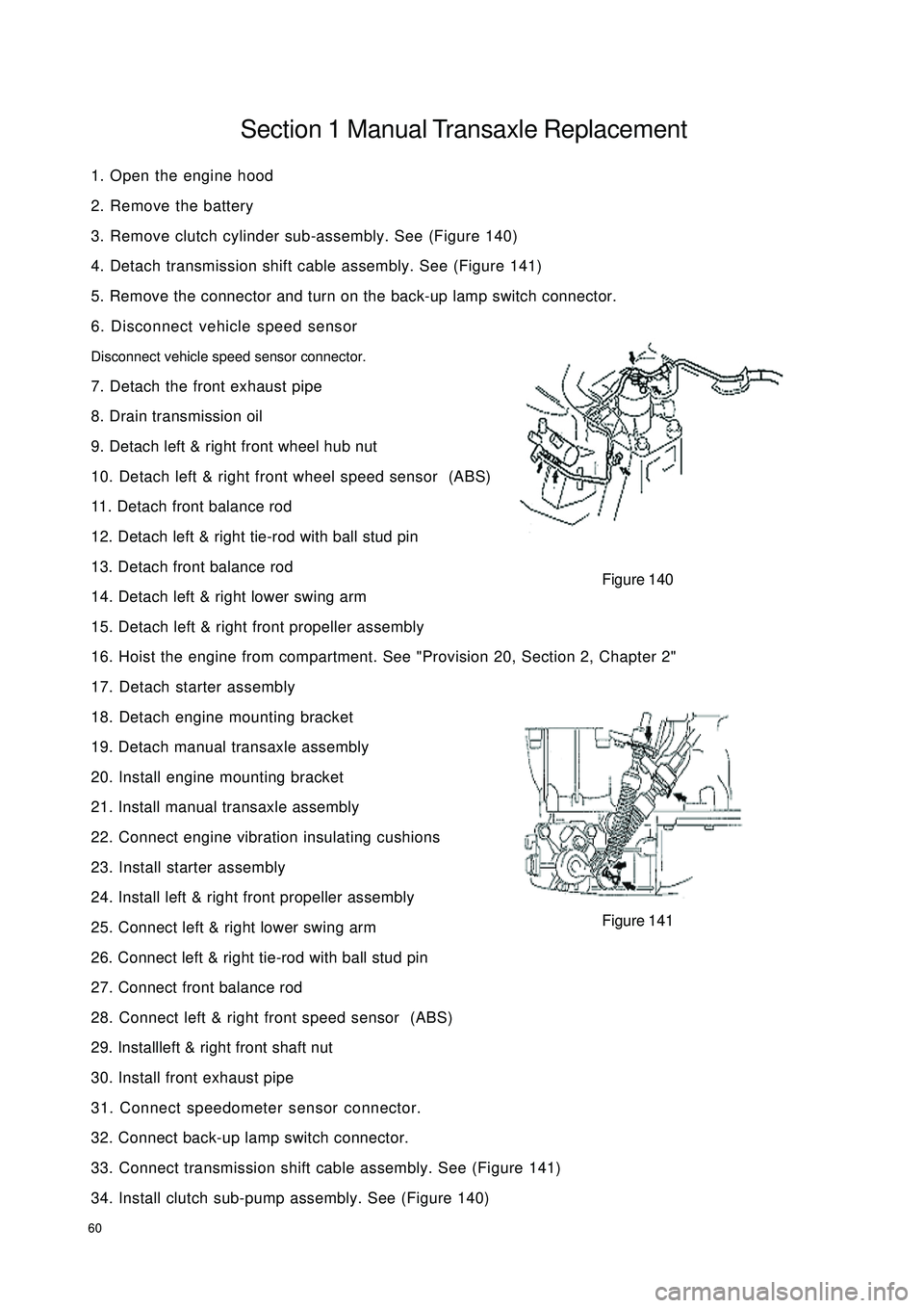
3. Remove clutch cylinder sub-assembly. See (Figure 140)
4. Detach transmission shift cable assembly. See (Figure 141)
5. Remove the connector and turn on the back-up lamp switch connector.
6. Disconnect vehicle speed sensor
Disconnect vehicle speed sensor connector.
7. Detach the front exhaust pipe
8. Drain transmission oil
9. Detach left & right front wheel hub nut
10. Detach left & right front wheel speed sensor (ABS)
11. Detach front balance rod
12. Detach left & right tie-rod with ball stud pin
13. Detach front balance rod
14. Detach left & right lower swing arm
15. Detach left & right front propeller assembly
16. Hoist the engine from compartment. See "Provision 20, Section 2, Chapter 2"
17. Detach starter assembly
18. Detach engine mounting bracket
19. Detach manual transaxle assembly
20. Install engine mounting bracket
21. Install manual transaxle assembly
22. Connect engine vibration insulating cushions
23. Install starter assembly
24. Install left & right front propeller assembly
25. Connect left & right lower swing arm
26. Connect left & right tie-rod with ball stud pin
27. Connect front balance rod
28. Connect left & right front speed sensor (ABS)
29. Installleft & right front shaft nut
30. Install front exhaust pipe
31. Connect speedometer sensor connector.
32. Connect back-up lamp switch connector.
33. Connect transmission shift cable assembly. See (Figure 141)
34. Install clutch sub-pump assembly. See (Figure 140)Figure 140
Figure 141
Page 95 of 392
88Replacement1. Remove shift lever assembly
(1) Pull upwards to separate shift lever assembly leather boot from the auxiliary console
(2) Loosen shift lever set screw with inner hex wrench. Remove the shift lever assembly counterclockwise.
2. Remove the auxiliary console
3. Remove the 4 nuts connecting manual shift assembly and the floor
4. Remove the shift cushion
5. Remove transmission control device assembly
(1) Remove the set nut on the cable seal press plate
(2) Remove the cotter pin and the flat washer connecting the cable and the rocker arm on the transmission
(3) Remove the E-shaped clip plate on the cable bracket retaining the cableShift Control
CablesE Shaped
Clip PlateBall SeatShift Lever Assembly LeverBall PinSpindle IISpindle IE Shaped
Clip PlateWave WasherBushBushSpring BushBall Pin Seat Torsion Spring Support
Plate Bottom BracketConjuction
Frame
Page 96 of 392

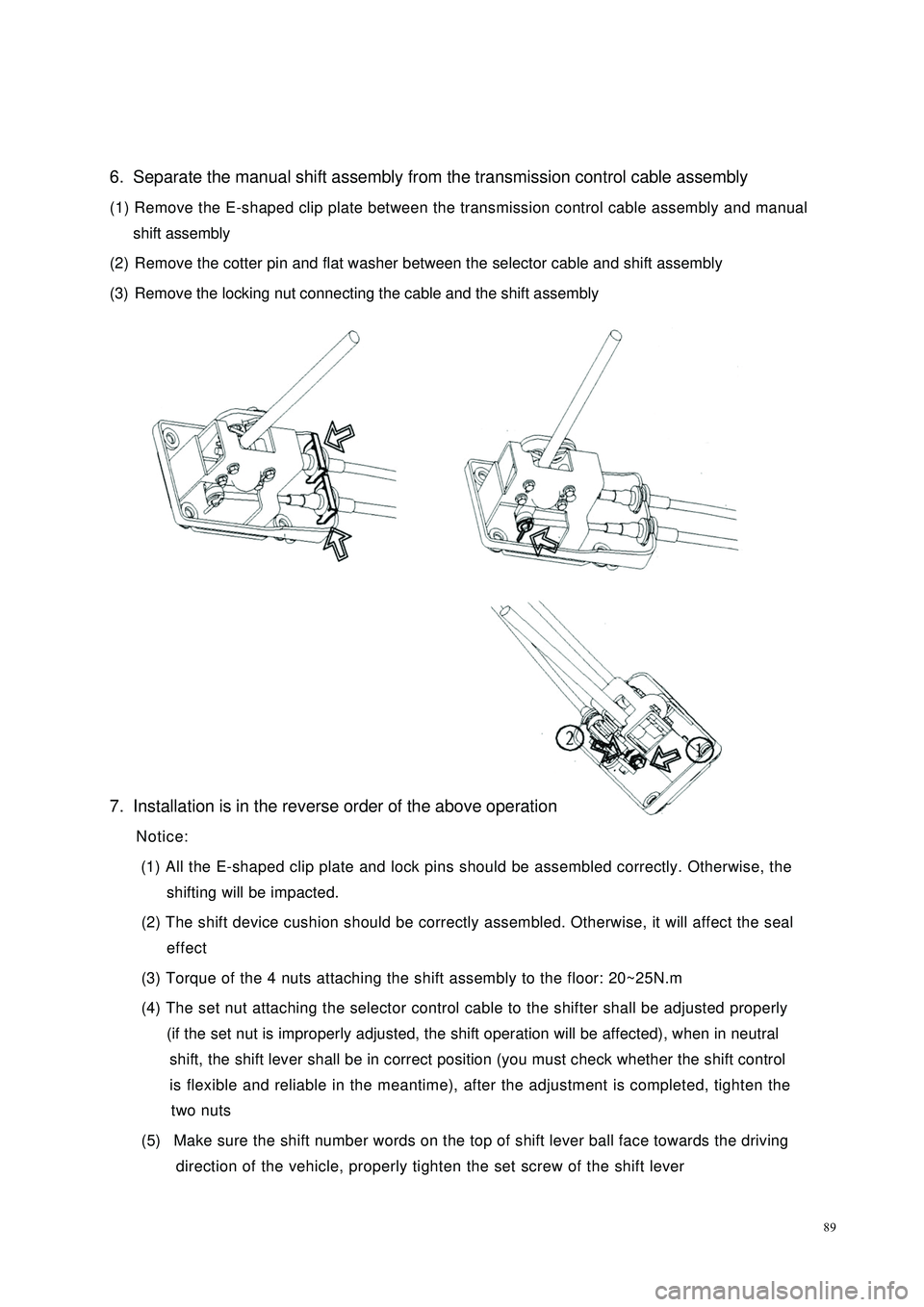
896. Separate the manual shift assembly from the transmission control cable assembly
(1) Remove the E-shaped clip plate between the transmission control cable assembly and manual
shift assembly
(2) Remove the cotter pin and flat washer between the selector cable and shift assembly
(3) Remove the locking nut connecting the cable and the shift assembly
7. Installation is in the reverse order of the above operation
Notice:
(1) All the E-shaped clip plate and lock pins should be assembled correctly. Otherwise, the
shifting will be impacted.
(2) The shift device cushion should be correctly assembled. Otherwise, it will affect the seal
effect
(3) Torque of the 4 nuts attaching the shift assembly to the floor: 20~25N.m
(4) The set nut attaching the selector control cable to the shifter shall be adjusted properly
(if the set nut is improperly adjusted, the shift operation will be affected), when in neutral
shift, the shift lever shall be in correct position (you must check whether the shift control
is flexible and reliable in the meantime), after the adjustment is completed, tighten the
two nuts
(5) Make sure the shift number words on the top of shift lever ball face towards the driving
direction of the vehicle, properly tighten the set screw of the shift lever