Page 225 of 392
218II. INSTALLATION1. Install the rear combination lamp and then the 3 mounting bolts.
2. Install the electrical connector.
3. Install the rear trunk interior trim.
4. Install the seal strip.III. REAR COMBINATION LAMP BULB REPLACEMENT1. Remove the O-ring seal.
2. Turn the lamp-holder counter-clockwise. Pull out the lamp-holder.
3. Remove the bulb and replace the bulb.Section 6 High Mounted Stop Lamp Replacement zRemove the High mounted stop lamp in direction 1 and 2. (as shown above in the illustration)
zDisconnect the connector.Partition
High Mounted
Stop Lamp
Page 226 of 392
219Section 7 Interior Dome Lamp Replacement1. Gently Pry the lamp shield off at the point a with a screwdriver.
2. Remove the 2 mounting bolts with a screwdriver (take care not to touch the bulb).
3. Pull the High mounted stop lamp assembly downwards.
4. Pull out the electrical connector.Roof Panel Interior Trim
Lamp Body
Lamp ShieldaFixing Screw
Page 227 of 392
220Roof Panel InteriorTrim
Rear Reading Lamp
(original status)Section 8 Rear Row Reading Lamp Replacement1. Gently pry the rear row reading lamp off at the point a with a screwdriver (Position 1 as shown in the
illustration).
2. Pull out the rear reading lamp downwards with an angle (Position 2 as shown in the illustration)
3. Remove the electrical connector.Section 9 License Plate Lamp Replacement1. Remove the license plate lamp with a screwdriver.
2. Remove the electrical connector.
Page 228 of 392

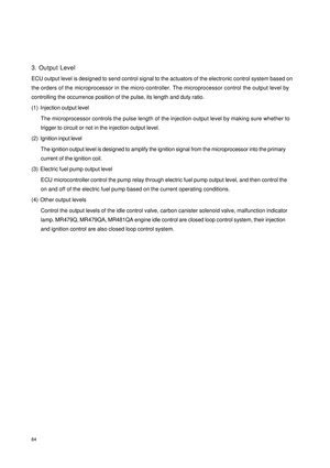
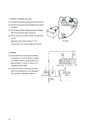
221Chapter 6 Audio SystemSection 1 Audio System DescriptionDescription:
1. Radio Wave Band
The radio wave bands used in radio broadcasting are as following:
LF: Low frequency
MF: Medium frequency
HF: High frequency
VHF: Very High frequency
2. Cover Area
There are great differences in the size of the
cover area for AM and FM monaural. Some-
times FM stereo broadcasts cannot be received
even though AM comes in very clearly. Not only
does FM stereo have the smallest cover area,
but it also picks up static and other types of in-
terference ("noise") easily.
3. Reception problems
Hint:
Besides the static noise fault, there are also the faults called "interference", "multipath transfer" and "fade
out". These faults are caused not by electrical noise but by the nature of the radio waves themselves.
(1) Interference
Besides static noise fault, AM broadcasts are
also susceptible to other types of noises, es-
pecially at night. This is because AM radio
waves are reflected by the Ionosphere at
night. These radio waves then interfere with
the signals from the same transmitter that
reach the vehicle's antenna directly. This type
of noise is called "interference".BandLF MF HF VHF
Ra dio wave AM FM
Modula tion Fre que nc y 30KHZ 300KHZ 3MHZ 30MHZ 300MHZ
Amplitude modula tion Fre que nc y modula tionFM (Stereo)FM (Monaural)InterferenceIonosphere
Page 229 of 392

222(2) Multipath transfer
Noise caused by bouncing of radio waves off
obstructions is called "multipath transfer".
Multipath transfer occurs when a signal from
the broadcast transmitter antenna reflects off
buildings and mountains and interferes with
the signal that is received directly.
(3) Fade out
Because FM radio waves are of higher frequen-
cies than AM radio waves, they are reflected
off buildings, mountains, and other obstructions.
For this reason, FM signals often seem to gradu-
ally disappear or fade away as the vehicle goes
behind a building or other obstructions. This is
called "fade out".
4. Noise faults
For noise troubleshooting it is very important to understand the feedback information from the customers
well, so make the best use of the following questionnaire and diagnose the fault accurately.
HINT:
In the case that the noise occurrence condition does not meet any of the above, check based on the "Recep-Multipath
TransferFade outR a dio W a veO pe ra ting c ondition w he n
noise oc c ursCause
Noise occurs at a specific
place.Strong possibility of fore ign noise .
Noise occurs when listening
to fa int broa dc asting.There is a case that the same program is broadcasted from
each local station and that may be the case you are liste ning
to different station if the program is the same.
N oise occ urs only at night.Strong possibility of the inte rfe re nce from fa r dista nt
broa dca sting.
N o is e o c c u r s w h ile d r iv in g
and at a specific place.Strong possibility of multipath tra nsfer inte rfe re nc e a nd
caused by the changes of FM waves. AM
FM
Page 230 of 392

223tion Problems".
5. COMPACT DISC PLAYER
Compact Disc Players (hereinafter referred as CD) use a laser beam pick--up to read the digital signals
recorded on the CD and reproduce analog signals of the music, etc.
HINT:
Never attempt to disassemble or oil any part of the player unit.
Do not insert any object other than a disc into the disc box.
NOTICE:
CD players use an invisible laser beam which could cause hazardous radiation exposure. Be sure
to operate the player correctly as instructed.
6. MAINTENANCE
(1) Tape player/magnet head cleaning:
1Raise the cassette door with your finger.
Next, using a pencil or similar object, push in
the guide.
2Using a cleaning pen or cotton applicator soaked
in cleaner, clean the magnet head surface, pinch
rollers and tape press wheel.
(2) CD player/disc cleaning:
If the disc gets dirty, clean the disc by wiping the surface
from the center to outside in the radial directions with a
soft cloth.
NOTICE:
Do not use a conventional record cleaner or anti--
static preservative.ExampleMagnet HeadTape Press WheelPinch Roller
Page 231 of 392

224Section 2 Audio System Connector Terminal Layout1. Connector terminal layout on wire harness
2. Connect terminal definitionTerminal
No.Func tion Wire color Condition Standard Voltage
A1 FR+ Lg The audio system is onWave form is synchronized w ith
the output sound
A2 FL+ YB The audio system is onWave form is synchronized w ith
the output sound
A3 ACC RW Ignition sw itc h turned to ACC 10
~14V
A4 B+ R Constant Status 10
~14V
A5 FR- LgR The audio system is onWave form is synchronized w ith
the output sound
A6 FL- Y The audio system is onWave form is synchronized w ith
the output sound
A7 GND B Constant Status Continuity
A8 N u ll
A9 N u ll
A1 0 T AI L G WPosition lamp switc h turned to
ON10
~14V
B1 RR+ PB The audio system is onWave form is synchronized w ith
the output sound
B2 RL+ YR The audio system is onWave form is synchronized w ith
the output sound
B3 RR- P The audio system is onWave form is synchronized w ith
the output sound
B4 N u ll
B5 N u ll
B6 RL- YW The audio system is onWave form is synchronized w ith
the output sound
C1 B+ Constant Status 10
~14V
C2 BUS Audio s ystem is On Pulse Signal
C3 GND Constant Status Continuity
C4 ACC Ignition sw itc h ACC 10
~14V
C5 Null
C6 R-OUT The audio system is onWave form is synchronized w ith
the output sound
C7 L-OUT The audio system is onWave form is synchronized w ith
the output sound
C8GND(Audio
Frequenc y)Constant Status Continuity
Page 232 of 392

225Section 3 Audio System InspectionI TroubleshootingSymptom
Suspected Area
1. Ra dio a ssembly c ircuit fa ulty
2. Ra dio a ssembly
1. Ra dio a ssembly bac klight te rmina l
2. Ra dio a ssembly
1. Spea ker c irc uit
2. Ra dio a ssembly powe r c ircuit faulty
3. Ra dio a ssembly
1. Spea ker c irc uit
2. Ra dio a ssembly powe r c ircuit faulty
3. Ra dio a ssembly
1. Ante nna c ircuit
2. Ra dio a ssembly
1. Ta pe
2. Ra dio a ssembly powe r c ircuit faulty
3. Ra dio a ssembly
1. Ta pe
2. Ra dio a ssembly
1. Ta pe
2. Ra dio a ssembly
1. Ta pe
2. Ra dio a ssembly
1. Wire betwe en CD box a nd main unit
2. CD P la ye r ma in unit pow e r supply c irc uit fa ult
3. CD box
4. CD Player main unit
1. Wire betwe en CD box a nd main unit
2. CD box
3. CD
4. CD Player main unit
1. Wire betwe en CD box a nd main unit
2. CD box
3. CD
4. CD PLAYER main unit
1. Wire betwe en CD box a nd main unit
2. CD box
1. CD box
2. CD box installa tion Sound quality poor only when pla ying CD
(Volume faint)
CD sound jump Tape ja mme d, ma lfunc tion with tape
speed or auto-reverse
CD could not be inserted or ejected after
ins e r t e d.
P owe r c oming in, but CD playe r not
operating.
CD ca n not be ta ke n out Una ble to re ce ive ra dio broa dca st (poor
re ce ption)
The c a ssette c ould not be inserted or
playe d
Cassette tape will not be ejected
Sound qua lity poor only whe n playing
cassette tape Ra dio not operating when powe r switch
turned to “ON”.
The radio ba cklight doe s not light up with
t he illumina t ion s w it c h O N
Spe ake r soundless in all modes
Sound qua lity poor in all mode s (Volume
faint)