2008 GEELY CK charging
[x] Cancel search: chargingPage 5 of 392

Section 8 Parking Brake System..................................................................................... 155........................................................157Chapter 1 Survey................................................................................................157
Chapter 2 Starting and Charging System.........................................................161Section 1 Starting System (MR479Q MR479QA MR481QA)..........................................161
Section 2 Charging System (MR479Q, MR479QA, MR481QA).......................................164Chapter 3 Combination Meter System..............................................................171Section 1 Circuit Diagram of Combination Meter and Location of Multi-pin Plug-in
Terminal............................................................................................................................ 171
Section 2 Malfunction Symptom Table and Solution Procedure...........................................174
Section 3 Combination Meter.......................................................................................... 187Chapter 4 Wiper and Washer System...............................................................193Section 1 Wiper and Washer System Inspection............................................................ 193
Section 2 Replacement and Adjustment............................................................................196Chapter 5 Light System......................................................................................198Section 1 Survey of Light System......................................................................................198
Section 2 Light System Symptom Inspection.................................................................. 202
Section 3 Headlamp Replacement....................................................................................211
Section 4 Front Fog Lamp Replacement............................................................................215
Section 5 Rear Combination Lamp Replacement..............................................................217
Section 6 High Mounted Stop Lamp Replacement............................................................218
Section 7 Interior Dome Lamp Replacement.....................................................................219
Section 8 Rear Row Reading Lamp Replacement...........................................................220
Section 9 License Plate Lamp Replacement...................................................................220Chapter 6 Audio System......................................................................................221Section 1 Audio System Description.................................................................................221
Section 2 Audio System Connector Terminal Layout...........................................................224
Section 3 Audio System Inspection................................................................................. 225
Section 4 Audio and Video System Replacement........................................................... 238Chapter 7 SRS (Supplemental Restraint System).............................................242Section 1 SRS-General Information.................................................................................242
Section 2 Troubleshooting................................................................................................ 251Part III Electrical Equipment
Page 71 of 392

64Chapter 9 General Engine Troubles and Their
TroubleshootingSection 1 Overview The wide application of the electronic technologies to the vehicles brings innovation on diagnosis of the
vehicle, many varieties of diagnosis instruments that are very effective and efficient for the vehicle diagnosis
are innovated. Once the fault occurs, the best choice is to go to service station for help. However, even the
most advanced instrument has its limit. For some faults, manual diagnosis is far more convenient and easier
than that of instrument. In case of the crack, distortion and leakage of the components, the manual diagnosis
is even superior to the instrument diagnosis. The faults occurred shall be carefully analyzed and troubleshot
in accordance with the repair manual for normal usage.Section 2 General Engine Fault and TroubleshootingI. Fuel pipeline and circuit fault causing the engine starting failureengine starting failure normally include: starter does not run or starter runs but fails to crank the engine, or
cranks the engine but cranks slowly; starter can crank but fail to start the engine. There are many causes that
result in starting failure, such as failures in starting system, ignition system, fuel injection system and engine
mechanical failure.
1. starter does not run or fails to crank the engine or cranks slowly
(1) Symptom: starter does not run or spongy rotation
(2) Causes:
b. Low battery voltage, excessive battery discharge, damaged generator or failure in charging circuit;
c. Battery terminal rust and backed out;
d. Failure in starting circuit, ECU can not receive STA signal;
e. Damaged starter.
2. engine can not start and crank
(1) Symptom
With the start switch on, starter can crank but fail to start the engine.
(2) Causes
a. Empty fuel tank;
b. Electrical fuel pump inoperative;
c. Injector inoperative;
d. Low fuel pressure;
e. Unreasonable starting operation;
f. Damaged throttle position sensor or no signal is sent to ECU due to the open in throttle position
sensor circuit;
Page 168 of 392

161Chapter 2 Starting and Charging SystemSection 1 Starting System
(MR479Q MR479QA MR481QA)I. STARTER INSPECTIONNOTICE:
These tests must be done within 5 seconds to avoid burning out the coil.
1. INSPECT MAGNETIC SWITCH
(a) Use wire to connect the starter as shown.
(b) Connect the magnetic switch and the battery as
shown.
(c) Disconnect the magnet exciting coil from the
terminal A.
(d) Check if the clutch pinion gear is moving out.
If the clutch pinion gear is not moving out, replace
the magnetic switch.
(e) Connect the battery as shown above. Disconnect
the battery positive (+) from the terminal, to make the clutch pinion gear disengaged.
(f) Check if the clutch pinion gear has returned.
If the clutch pinion gear has not returned, replace
the magnetic switch.Terminal ABatteryBatteryDisconnect
Page 171 of 392

164Section 2 Charging System
(MR479Q, MR479QA, MR481QA)I. BATTERYMaintenance-free battery is applied in this vehicle. Its termination voltage is 12V. It is connected inline by six
2V single cell in tandem with walls between every pole.
1. BATTERY WARNING SIGNS
1 -- Danger of corrosion
The battery electrolyte is very corrosive. DO NOT overturn the battery.
2 -- Read the instructions for battery
3 -- Children are forbidden to touch the battery
4 -- Avoid fire, electromagnetic wave and strong light.
Avoid electric spark while repair; avoid short.
5 -- Wear protecting glasses
6 -- Danger of explosion
The explosive mixed gas will be produced while charging.
7 -- How to deal with a scrapped battery
The scrapped battery should be delivered to the collection station.1234567
Page 173 of 392

166II. CHARGING SYSTEM INSPECTION1. CHECK BATTERY WORKING VOLTAGE
(a) After having driven the vehicle and in the case that 20 minutes have not passed after having stopped the
engine, turn the ignition switch ON and turn on the electrical system (headlight, blower motor) for 60
seconds to remove the surface charge.
(b) Turn the ignition switch OFF and
turn off the electrical systems. Then
measure the battery voltage
between the negative and positive
terminals of the battery.
Standard voltage: 12.5-12.9V at
20°C
HINT:
If the voltage is less than specification, charge the battery.
2. CHECK BATTERY TERMINALS, FUSE BOX AND FUSE
(a) Check that the battery terminals are not loose or corroded.
(b) Check if fuse box and fuse for continuity.
Page 175 of 392

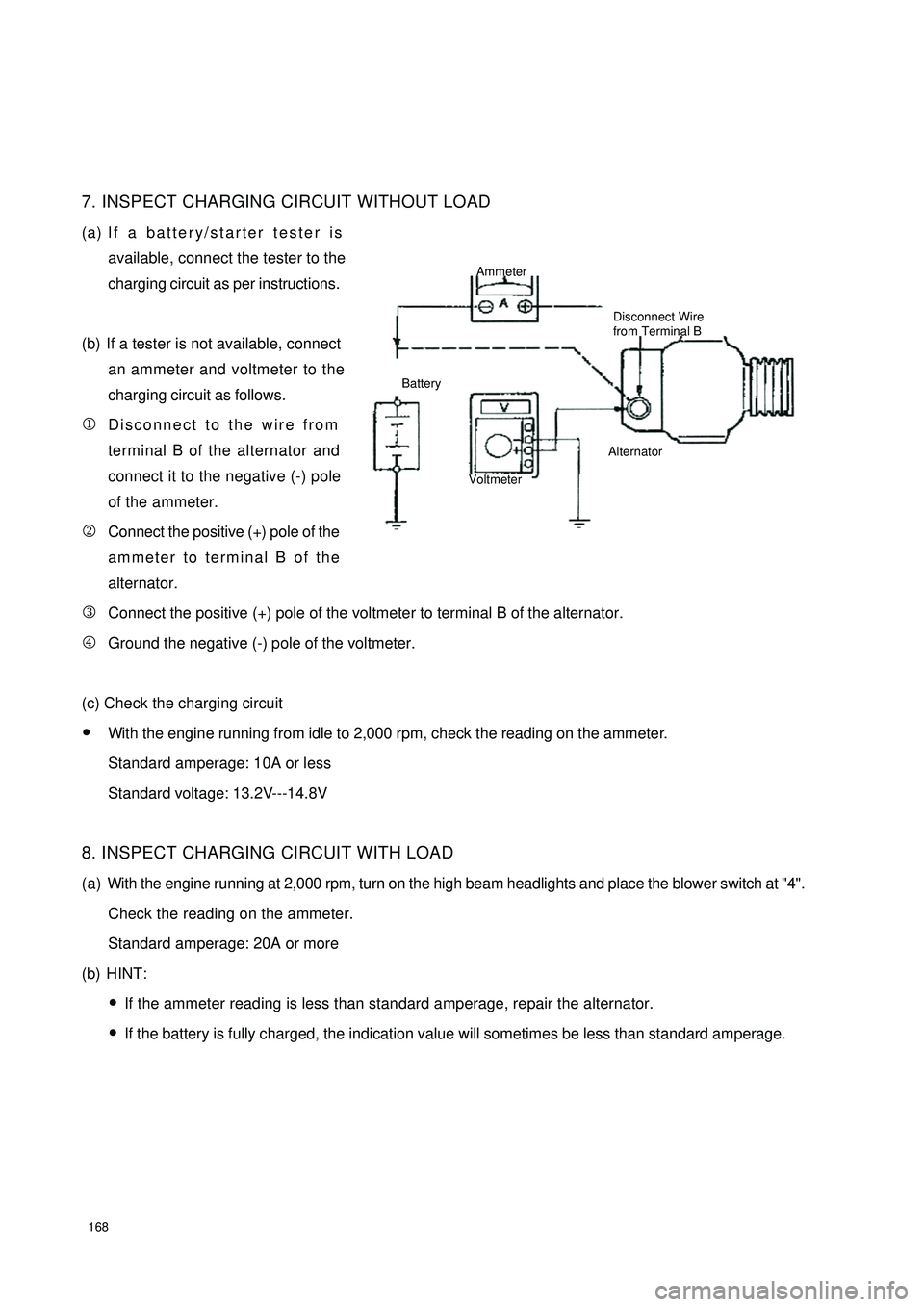
1687. INSPECT CHARGING CIRCUIT WITHOUT LOAD
(a) If a battery/starter tester is
available, connect the tester to the
charging circuit as per instructions.
(b) If a tester is not available, connect
an ammeter and voltmeter to the
charging circuit as follows.
1Disconnect to the wire from
terminal B of the alternator and
connect it to the negative (-) pole
of the ammeter.
2Connect the positive (+) pole of the
ammeter to terminal B of the
alternator.
3Connect the positive (+) pole of the voltmeter to terminal B of the alternator.
4Ground the negative (-) pole of the voltmeter.
(c) Check the charging circuit
�yWith the engine running from idle to 2,000 rpm, check the reading on the ammeter.
Standard amperage: 10A or less
Standard voltage: 13.2V---14.8V
8. INSPECT CHARGING CIRCUIT WITH LOAD
(a) With the engine running at 2,000 rpm, turn on the high beam headlights and place the blower switch at "4".
Check the reading on the ammeter.
Standard amperage: 20A or more
(b) HINT:
�yIf the ammeter reading is less than standard amperage, repair the alternator.
�yIf the battery is fully charged, the indication value will sometimes be less than standard amperage.Ammeter
Disconnect Wire
from Terminal B
Battery
VoltmeterAlternator
Page 259 of 392

252(3)Check the connection between ECU and instrument cluster
1Turn the ignition switch to LOCK.
2Disconnect the negative (-) terminal cable from the battery.
3Disconnect the connector of instrument cluster.
4Check if the related circuits of the warning light are connected or not.
Yes: continue with next step.
No: replace the wire harness, and then continue with step 5.
2. SRS warning light remains on.DIAGNOSTIC PROCEDURESTo begin the check, first use special diagnostic instruments and ECU to perform communication diagnosis
and find out the causes of the trouble. If the communication fails, continue with the following procedures:
(1) Check battery
1Check battery voltage.
2Is voltage higher than 9V?
Yes: continue with next step.
No: Insufficient battery supply. Check the charging/discharging system, and then continue with step (5).
(2) Check the continuity of the wire harness between ECU and instrument cluster
1Turn the ignition switch to LOCK.
2Disconnect negative (-) terminal cable from the battery.
3Open the guard plate of the central passage.
4Disconnect the connector of the instrument cluster.
5Connect the negative (-) terminal cable of the battery.
6Turn the ignition switch ON.
7Check whether the voltage of the connector terminal of the instrument is 12V (power supply and instrument
connecting wire).Trouble Che cking Sta tus P ossible Cause�z Insufficient battery supply�z ECU internal trouble�z SRS wa rning light trouble of instrument c luste r�z Improper connection of ECU connector�z P oor c ontac t of instrume nt c luste r c onne c tor�z Ope n circ uit or poor c onta c t of ECU power supply fuse�z P oor c onne c tion of ECU connec tor te rmina l�z P oor conta ct of the wire ha rne ss be twe en ECU
connec tor te rmina l a nd ground�z Drive r or pa ssenge r side circ uit trouble of SRS SRS wa rning light
remains onSRS warning light
remains on
Page 261 of 392

2543.Internal trouble
4. Power troubleDIAGNOSTIC PROCEDURES(1) Check battery
�yIs the battery voltage measured higher than 9V?
Yes: continue with next step.
No: low battery voltage, check the charging/discharging system.
�ySee Chapter I, Charging System-Battery Checking
(2) Check the wire harness between battery and fuse box
�yRemove fuse box and turn the ignition switch ON, without loosening connector.
�yMeasure and see if the electrical potential between two terminals of the fuse box is more than 9V.
Yes: continue with next step.
No: check the wire harness.DTC B1620 Internal trouble of SRS unitCAUTION
●
Condition for running the DTC is to inspec t the dia gnostic trouble code that
ma y not a ppe a r prior to this te st. P e rforming this te st ma y re sults in body injury orda ma ge d system due to misoperations. The re fore , prepa ra tions must be ma debefore checking.
●
Internal circuit trouble of SRS ECU
P ossible Ca use Interna l trouble of SRS unit
Operation
Replace the SRS unit, see SRS System, Removal & Installation of SRS Unit Che c king ConditionsDTC B1112 Low power source voltage of SRS ECU
CAUTION
Condition for running the DTC is to inspe ct the diagnostic trouble c ode that ma y not
a ppea r prior to this test. P e rforming this te st ma y re sults in body injury or da ma ge dsyste m due to misoperations. Therefore, prepa ra tions must be ma de beforechecking.
●
The e lec tric a l pote ntia l be twe e n pins 5 a nd 6 of the c onne c tor of SRS unit is
le s s t ha n 9V .
●
Low batte ry volta ge
Trouble in wire ha rne ss betwe e n ba tte ry and SRS ECU C he c king C ondit ions
P os s ible C a us e