Page 1464 of 3000

AX–98U151E AUTOMATIC TRANSAXLE – AUTOMATIC TRANSAXLE SYSTEM
AX
DESCRIPTION
This sensor detects the rotation speed of the counter gear. By comparing the counter gear speed signal
(NC) with the direct clutch speed sensor signal (NT), the ECM detects the shift timing of the gears and
appropriately controls the engine torque and hydraulic pressure according to various conditions. Thus
smooth gear shifting is performed.
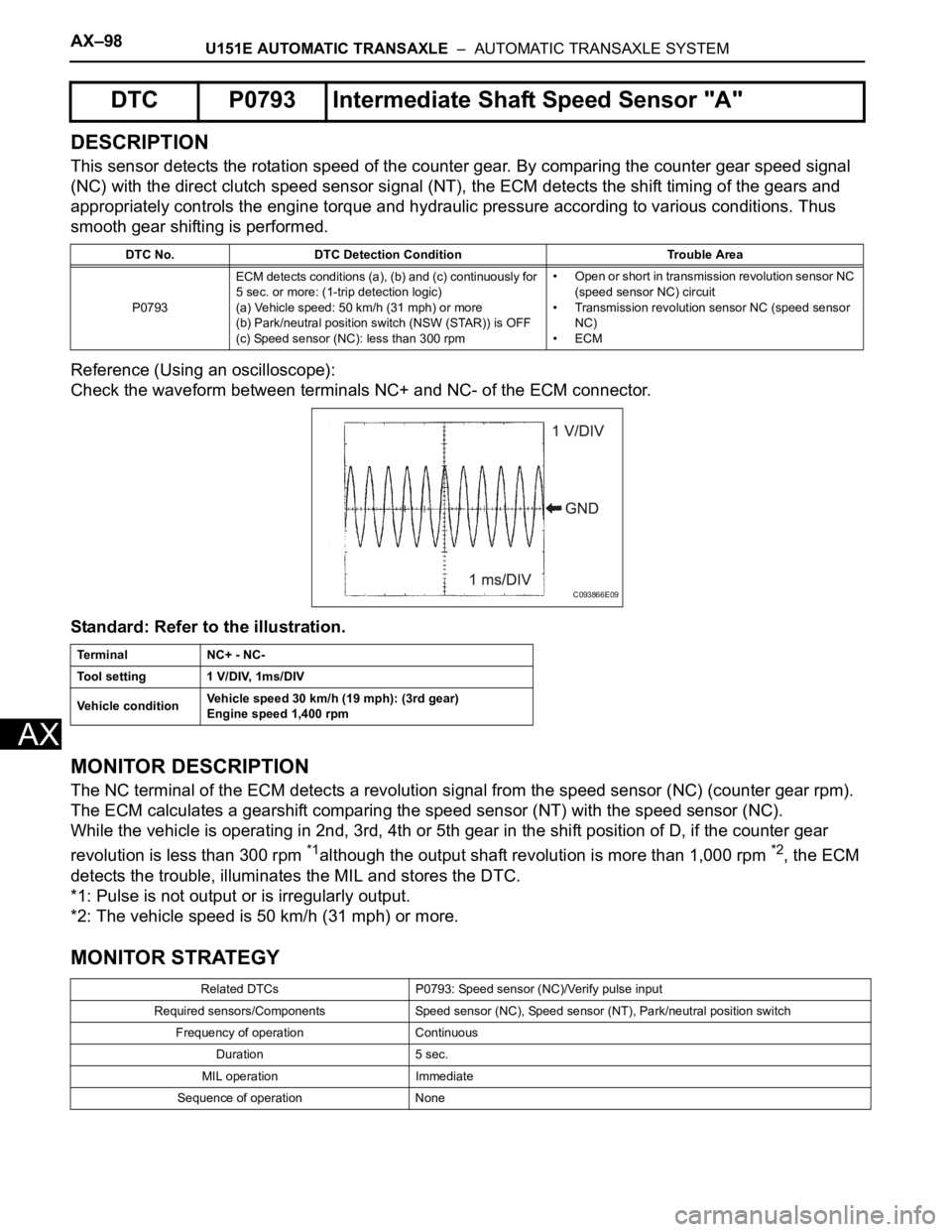
Reference (Using an oscilloscope):
Check the waveform between terminals NC+ and NC- of the ECM connector.
Standard: Refer to the illustration.
MONITOR DESCRIPTION
The NC terminal of the ECM detects a revolution signal from the speed sensor (NC) (counter gear rpm).
The ECM calculates a gearshift comparing the speed sensor (NT) with the speed sensor (NC).
While the vehicle is operating in 2nd, 3rd, 4th or 5th gear in the shift position of D, if the counter gear
revolution is less than 300 rpm
*1although the output shaft revolution is more than 1,000 rpm *2, the ECM
detects the trouble, illuminates the MIL and stores the DTC.
*1: Pulse is not output or is irregularly output.
*2: The vehicle speed is 50 km/h (31 mph) or more.
MONITOR STRATEGY
DTC P0793 Intermediate Shaft Speed Sensor "A"
DTC No. DTC Detection Condition Trouble Area
P0793ECM detects conditions (a), (b) and (c) continuously for
5 sec. or more: (1-trip detection logic)
(a) Vehicle speed: 50 km/h (31 mph) or more
(b) Park/neutral position switch (NSW (STAR)) is OFF
(c) Speed sensor (NC): less than 300 rpm• Open or short in transmission revolution sensor NC
(speed sensor NC) circuit
• Transmission revolution sensor NC (speed sensor
NC)
•ECM
Te r m i n a l N C + - N C -
Tool setting 1 V/DIV, 1ms/DIV
Vehicle conditionVehicle speed 30 km/h (19 mph): (3rd gear)
Engine speed 1,400 rpm
Related DTCs P0793: Speed sensor (NC)/Verify pulse input
Required sensors/Components Speed sensor (NC), Speed sensor (NT), Park/neutral position switch
Frequency of operation Continuous
Duration 5 sec.
MIL operation Immediate
Sequence of operation None
C093866E09
Page 1468 of 3000

AX–102U151E AUTOMATIC TRANSAXLE – AUTOMATIC TRANSAXLE SYSTEM
AX
SYSTEM DESCRIPTION
The ECM uses signals from the vehicle speed sensor to detect the actual gear position (1st, 2nd, 3rd, 4th
or 5th gear).
Then the ECM compares the actual gear with the shift schedule in the ECM memory to detect mechanical
troubles of the shift solenoid valves and valve body.
MONITOR DESCRIPTION
The ECM commands gear shifts by turning the shift solenoid valves "ON/OFF". According to the input
shaft revolution, intermediate (counter) shaft revolution and output shaft revolution, the ECM detects the
actual gear position (1st, 2nd, 3rd, 4th or 5th gear position). When the gear position commanded by the
ECM and the actual gear position are not the same, the ECM illuminates the MIL and stores the DTC.
MONITOR STRATEGY
TYPICAL ENABLING CONDITIONS
All:
DTC P0796Pressure Control Solenoid "C" Performance
(Shift Solenoid Valve SL3)
DTC No. DTC Detection Condition Trouble Area
P0796The gear required by the ECM does not match the
actual gear when driving (2-trip detection logic)• Shift solenoid valve SL3 remains open or closed
• Valve body is blocked
• Automatic transaxle (clutch, brake or gear etc.)
Related DTCsP0796:
Shift solenoid valve SL3/OFF malfunction
Shift solenoid valve SL3/ON malfunction
Required sensors/ComponentsShift solenoid valve SL3, Speed sensor (NT), Speed sensor (NC), Crankshaft
position sensor (NE)
Frequency of operation Continuous
DurationOFF malfunction (A)
0.8 sec.
OFF malfunction (B)
1 sec.
ON malfunction (A) and (B)
0.8 sec.
ON malfunction (C)
0.4 sec.
MIL operation 2 driving cycles
Sequence of operation None
The monitor will run whenever this DTC is not present.P0115 - P0118 (ECT sensor)
P0125 (Insufficient ECT for closed loop)
P0500 (VSS)
P0748, P0778, P0798 (Shift solenoid valve (range))
ECT (Engine coolant temperature) 10
C (50F) or more
Transmission range"D"
TFT (Transmission fluid temperature) -20
C (-4F) or more
TFT sensor circuitNot circuit malfunction
ECT sensor circuitNot circuit malfunction
Turbine speed sensor circuit Not circuit malfunction
Intermediate shaft speed sensor circuit Not circuit malfunction
Output speed sensor circuit Not circuit malfunction
Shift solenoid valve SL1 circuit Not circuit malfunction
Shift solenoid valve SL2 circuit Not circuit malfunction
Page 1471 of 3000

U151E AUTOMATIC TRANSAXLE – AUTOMATIC TRANSAXLE SYSTEMAX–105
AX
HINT:
If any other codes besides "P0796" are output, perform
the troubleshooting for those DTCs first.
B
A
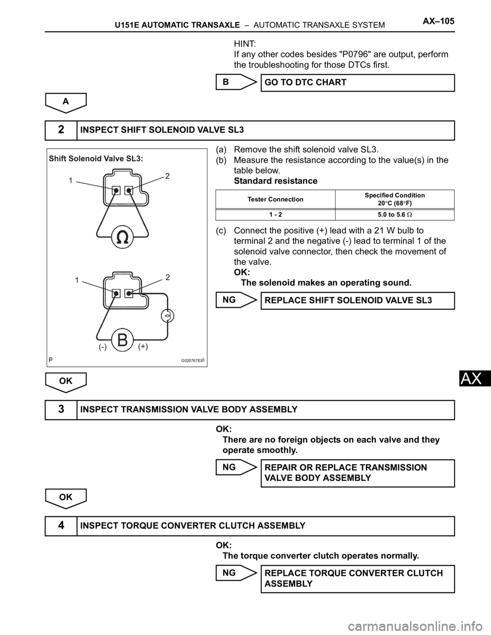
(a) Remove the shift solenoid valve SL3.
(b) Measure the resistance according to the value(s) in the
table below.
Standard resistance
(c) Connect the positive (+) lead with a 21 W bulb to
terminal 2 and the negative (-) lead to terminal 1 of the
solenoid valve connector, then check the movement of
the valve.
OK:
The solenoid makes an operating sound.
NG
OK
OK:
There are no foreign objects on each valve and they
operate smoothly.
NG
OK
OK:
The torque converter clutch operates normally.
NGGO TO DTC CHART
2INSPECT SHIFT SOLENOID VALVE SL3
G020767E81
Tester ConnectionSpecified Condition
20C (68F)
1 - 2 5.0 to 5.6
REPLACE SHIFT SOLENOID VALVE SL3
3INSPECT TRANSMISSION VALVE BODY ASSEMBLY
REPAIR OR REPLACE TRANSMISSION
VALVE BODY ASSEMBLY
4INSPECT TORQUE CONVERTER CLUTCH ASSEMBLY
REPLACE TORQUE CONVERTER CLUTCH
ASSEMBLY
Page 1474 of 3000
AX–108U151E AUTOMATIC TRANSAXLE – AUTOMATIC TRANSAXLE SYSTEM
AX
WIRING DIAGRAM
INSPECTION PROCEDURE
(a) Disconnect the transmission wire connector from the
transaxle.
(b) Measure the resistance according to the value(s) in the
table below.
Standard resistance
(c) Measure the resistance according to the value(s) in the
table below.
Standard resistance (Check for short)
NG
OK
1INSPECT TRANSMISSION WIRE (SL3)
G031765E60
C113969E05
Tester ConnectionSpecified Condition
20C (68F)
4 (SL3+) - 11 (SL3-) 5.0 to 5.6
Tester Connection Specified Condition
4 (SL3+) - Body ground 10 k
or higher
11 (SL3-) - Body ground
Go to step 3
Page 1475 of 3000

U151E AUTOMATIC TRANSAXLE – AUTOMATIC TRANSAXLE SYSTEMAX–109
AX
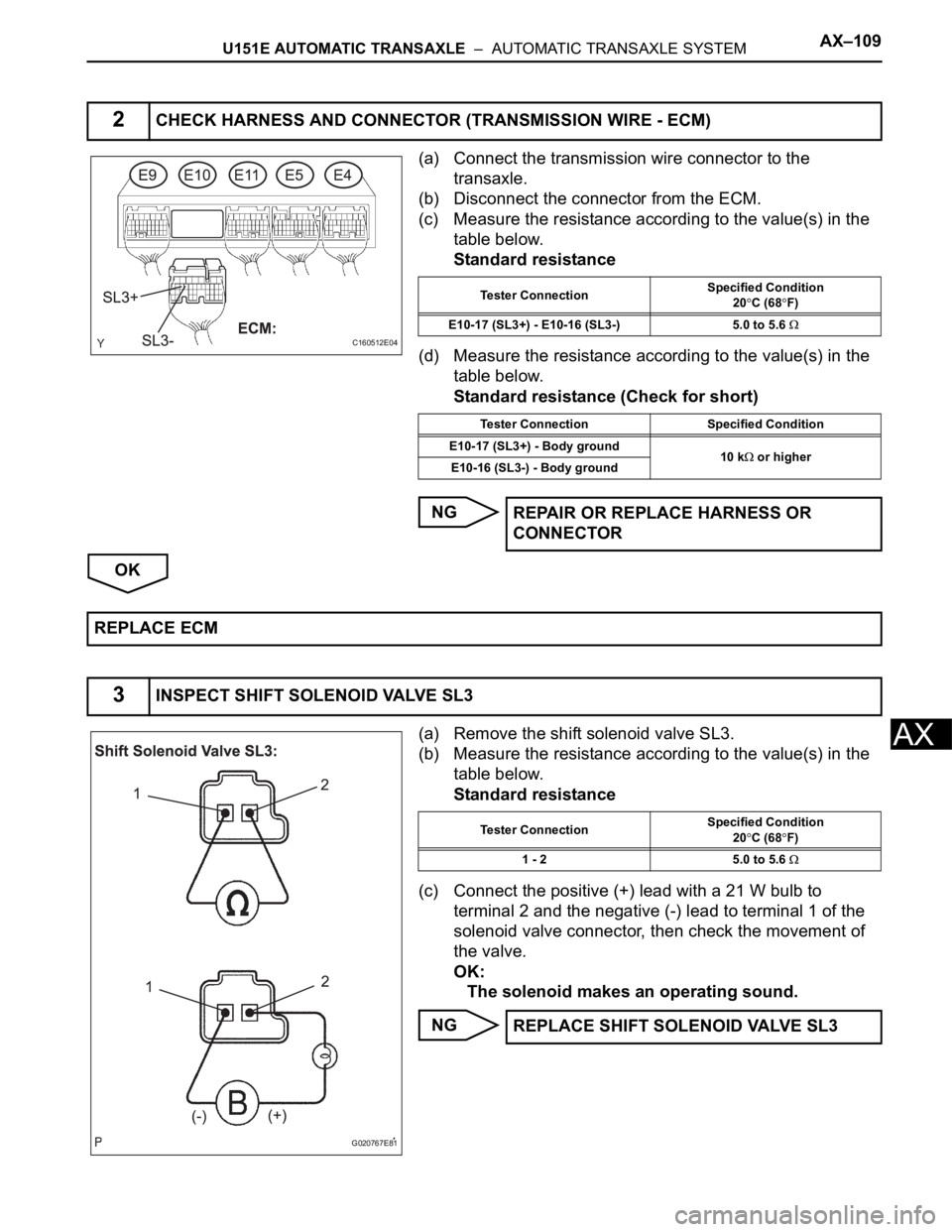
(a) Connect the transmission wire connector to the
transaxle.
(b) Disconnect the connector from the ECM.
(c) Measure the resistance according to the value(s) in the
table below.
Standard resistance
(d) Measure the resistance according to the value(s) in the
table below.
Standard resistance (Check for short)
NG
OK
(a) Remove the shift solenoid valve SL3.
(b) Measure the resistance according to the value(s) in the
table below.
Standard resistance
(c) Connect the positive (+) lead with a 21 W bulb to
terminal 2 and the negative (-) lead to terminal 1 of the
solenoid valve connector, then check the movement of
the valve.
OK:
The solenoid makes an operating sound.
NG
2CHECK HARNESS AND CONNECTOR (TRANSMISSION WIRE - ECM)
C160512E04
Tester ConnectionSpecified Condition
20C (68F)
E10-17 (SL3+) - E10-16 (SL3-) 5.0 to 5.6
Tester Connection Specified Condition
E10-17 (SL3+) - Body ground
10 k
or higher
E10-16 (SL3-) - Body ground
REPAIR OR REPLACE HARNESS OR
CONNECTOR
REPLACE ECM
3INSPECT SHIFT SOLENOID VALVE SL3
G020767E81
Tester ConnectionSpecified Condition
20C (68F)
1 - 2 5.0 to 5.6
REPLACE SHIFT SOLENOID VALVE SL3
Page 1476 of 3000
AX–110U151E AUTOMATIC TRANSAXLE – AUTOMATIC TRANSAXLE SYSTEM
AX
OK
REPAIR OR REPLACE TRANSMISSION WIRE
Page 1478 of 3000
AX–112U151E AUTOMATIC TRANSAXLE – AUTOMATIC TRANSAXLE SYSTEM
AX
TYPICAL MALFUNCTION THRESHOLDS
P0982: Range check (Low resistance):
P0983: Range check (High resistance):
COMPONENT OPERATING RANGE
WIRING DIAGRAM
INSPECTION PROCEDURE
(a) Disconnect the transmission wire connector from the
transaxle.
(b) Measure the resistance according to the value(s) in the
table below.
Standard resistance
NG
OK
Shift solenoid valve S4 resistance 8 or less
Shift solenoid valve S4 resistance 100 k
or more
Shift solenoid valve S4 Resistance: 11 to 15
at 20C (68F)
1INSPECT TRANSMISSION WIRE (S4)
G031165E82
C113969E07
Tester ConnectionSpecified Condition
20C (68F)
3 (S4) - Body ground 11 to 15
Go to step 3
Page 1479 of 3000

U151E AUTOMATIC TRANSAXLE – AUTOMATIC TRANSAXLE SYSTEMAX–113
AX
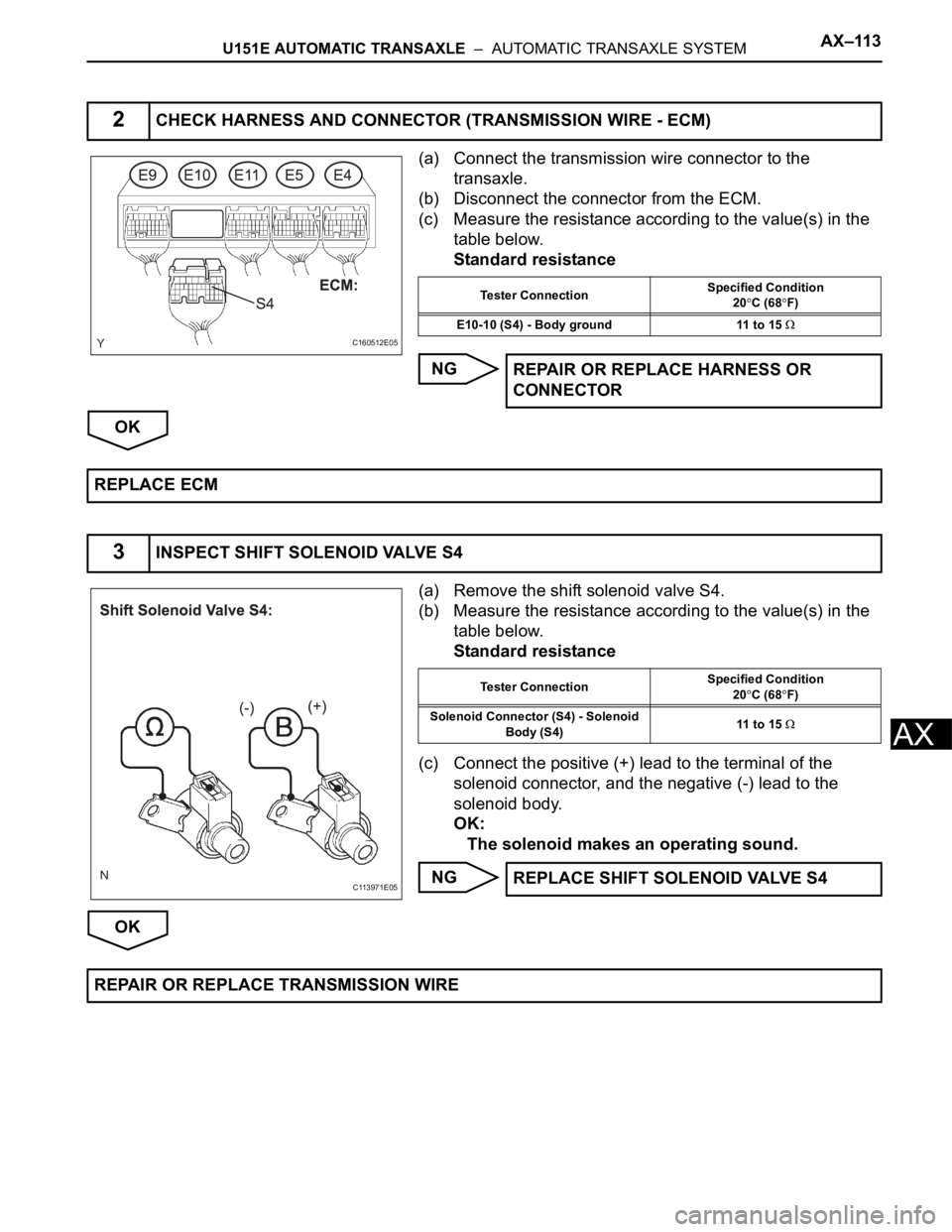
(a) Connect the transmission wire connector to the
transaxle.
(b) Disconnect the connector from the ECM.
(c) Measure the resistance according to the value(s) in the
table below.
Standard resistance
NG
OK
(a) Remove the shift solenoid valve S4.
(b) Measure the resistance according to the value(s) in the
table below.
Standard resistance
(c) Connect the positive (+) lead to the terminal of the
solenoid connector, and the negative (-) lead to the
solenoid body.
OK:
The solenoid makes an operating sound.
NG
OK
2CHECK HARNESS AND CONNECTOR (TRANSMISSION WIRE - ECM)
C160512E05
Tester ConnectionSpecified Condition
20C (68F)
E10-10 (S4) - Body ground 11 to 15
REPAIR OR REPLACE HARNESS OR
CONNECTOR
REPLACE ECM
3INSPECT SHIFT SOLENOID VALVE S4
C113971E05
Tester ConnectionSpecified Condition
20C (68F)
Solenoid Connector (S4) - Solenoid
Body (S4)11 to 15
REPLACE SHIFT SOLENOID VALVE S4
REPAIR OR REPLACE TRANSMISSION WIRE