2007 TOYOTA SIENNA automatic transmission
[x] Cancel search: automatic transmissionPage 1399 of 3000
AX–22U151E AUTOMATIC TRANSAXLE – AUTOMATIC TRANSAXLE SYSTEM
AX
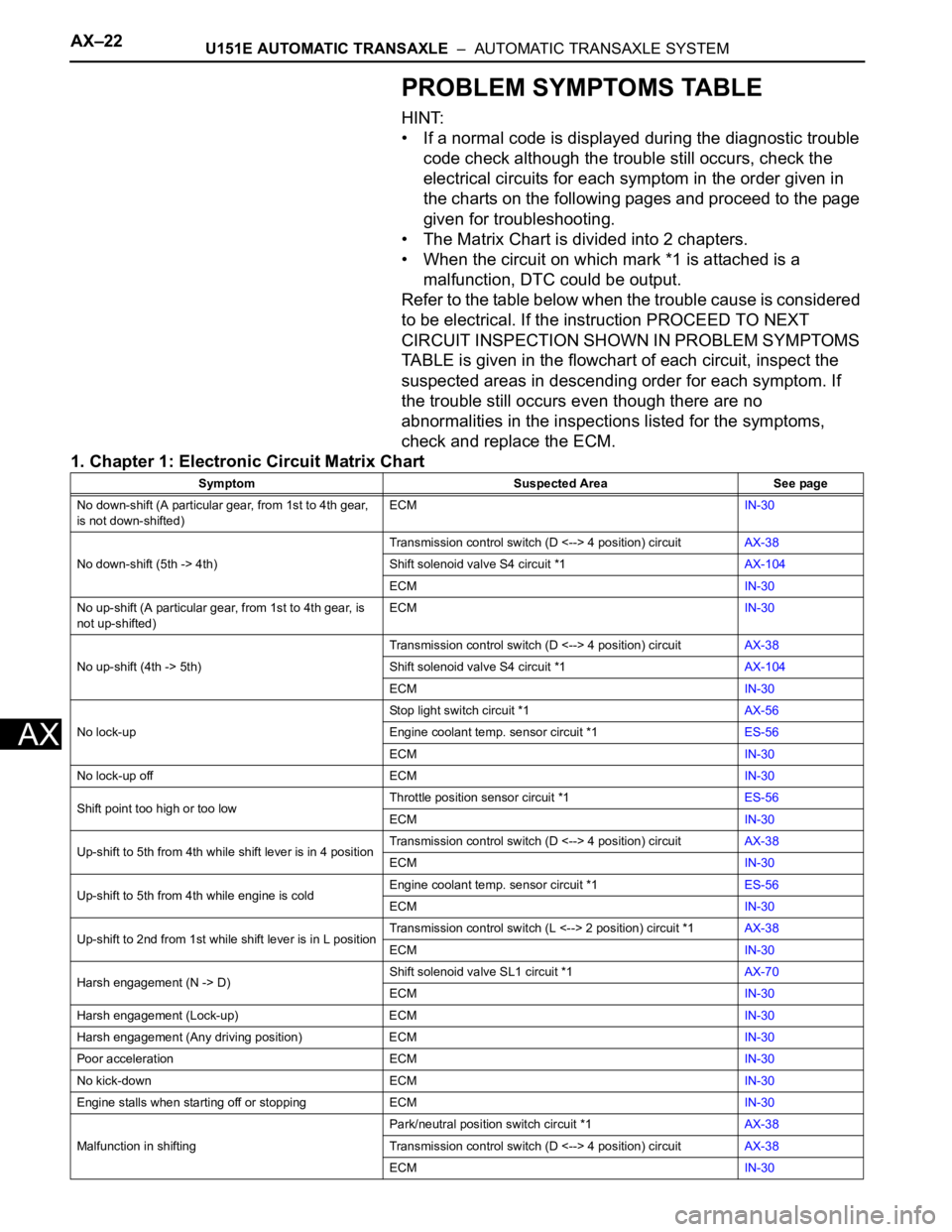
PROBLEM SYMPTOMS TABLE
HINT:
• If a normal code is displayed during the diagnostic trouble
code check although the trouble still occurs, check the
electrical circuits for each symptom in the order given in
the charts on the following pages and proceed to the page
given for troubleshooting.
• The Matrix Chart is divided into 2 chapters.
• When the circuit on which mark *1 is attached is a
malfunction, DTC could be output.
Refer to the table below when the trouble cause is considered
to be electrical. If the instruction PROCEED TO NEXT
CIRCUIT INSPECTION SHOWN IN PROBLEM SYMPTOMS
TABLE is given in the flowchart of each circuit, inspect the
suspected areas in descending order for each symptom. If
the trouble still occurs even though there are no
abnormalities in the inspections listed for the symptoms,
check and replace the ECM.
1. Chapter 1: Electronic Circuit Matrix Chart
Symptom Suspected Area See page
No down-shift (A particular gear, from 1st to 4th gear,
is not down-shifted)ECMIN-30
No down-shift (5th -> 4th)Transmission control switch (D <--> 4 position) circuitAX-38
Shift solenoid valve S4 circuit *1AX-104
ECMIN-30
No up-shift (A particular gear, from 1st to 4th gear, is
not up-shifted)ECMIN-30
No up-shift (4th -> 5th)Transmission control switch (D <--> 4 position) circuitAX-38
Shift solenoid valve S4 circuit *1AX-104
ECMIN-30
No lock-upStop light switch circuit *1AX-56
Engine coolant temp. sensor circuit *1ES-56
ECMIN-30
No lock-up off ECMIN-30
Shift point too high or too lowThrottle position sensor circuit *1ES-56
ECMIN-30
Up-shift to 5th from 4th while shift lever is in 4 positionTransmission control switch (D <--> 4 position) circuitAX-38
ECMIN-30
Up-shift to 5th from 4th while engine is coldEngine coolant temp. sensor circuit *1ES-56
ECMIN-30
Up-shift to 2nd from 1st while shift lever is in L positionTransmission control switch (L <--> 2 position) circuit *1AX-38
ECMIN-30
Harsh engagement (N -> D)Shift solenoid valve SL1 circuit *1AX-70
ECMIN-30
Harsh engagement (Lock-up) ECMIN-30
Harsh engagement (Any driving position) ECMIN-30
Poor acceleration ECMIN-30
No kick-down ECMIN-30
Engine stalls when starting off or stopping ECMIN-30
Malfunction in shiftingPark/neutral position switch circuit *1AX-38
Transmission control switch (D <--> 4 position) circuitAX-38
ECMIN-30
Page 1406 of 3000

AX–36U151E AUTOMATIC TRANSAXLE – AUTOMATIC TRANSAXLE SYSTEM
AX
FAIL-SAFE CHART
1. FAIL-SAFE
This function minimizes the loss of the ECT functions
when any malfunction occurs in a sensor or solenoid.
(a) ATF (Automatic Transmission Fluid) temperature
sensor:
When the ATF temperature sensor has a
malfunction, 5th upshift is prohibited.
(b) Counter gear speed sensor NC (Speed sensor NC):
When the counter gear speed sensor has a
malfunction, 5th upshift is prohibited.
(c) Shift solenoid valve DSL:
When the solenoid valve DSL has a malfunction, the
current to the solenoid valve is stopped.
This stops lock-up control, then fuel economy
decreases.
(d) Shift solenoid valve SL1, SL2, SL3 and S4:
Fail safe function:
If either of the shift solenoid valve circuits develops
an open or short, the ECM turns the other shift
solenoid "ON" and "OFF" in order to shift into the
gear positions shown in the table below.
Manual shifting as shown in the following table must
be done (In case of a short circuit, the ECM stops
sending the current to the short circuited solenoid).
Even if starting the engine in the fail-safe mode, the
gear position remains in the same position.
HINT:
FL: Flex Lock-up
NormalSolenoid ValveSL1 ON OFF ON OFF OFF
SL2 ON ON OFF FL FL
SL3 OFF OFF OFF ON ON
S4 OFF OFF OFF OFF ON
Gear Position 1st 2nd 3rd 4th 5th
SL1
Malfunction
(During driving
at 1st or 2nd)Solenoid ValveSL1 OFF
SL2 ON ON OFF to ON FL to ON FL to ON
SL3 OFF OFF OFF ON to OFF ON to OFF
S4 OFF OFF OFF OFF ON to OFF
Gear Position 1st to 2nd 2nd 3rd to 2nd 4th to 2nd 5th to 2nd
SL1
Malfunction
(During driving
at 3rd)Solenoid ValveSL1 OFF
SL2 ON to FL ON to FL OFF to FL FL FL
SL3 OFF OFF OFF ON to OFF ON to OFF
S4 OFF to ON OFF to ON OFF to ON OFF to ON ON
Gear Position 1st to 4th 2nd to 4th 3rd to 4th 4th 5th to 4th
SL1
Malfunction
(During driving
at 4th or 5th)Solenoid ValveSL1 OFF
SL2 ON to FL ON to FL OFF to FL FL FL
SL3 OFF to ON OFF to ON OFF to ON ON ON
S4 OFF OFF OFF OFF ON
Gear Position 1st to 4th 2nd to 4th 3rd to 4th 4th 5th to 4th
Page 1408 of 3000
AX–42U151E AUTOMATIC TRANSAXLE – AUTOMATIC TRANSAXLE SYSTEM
AX
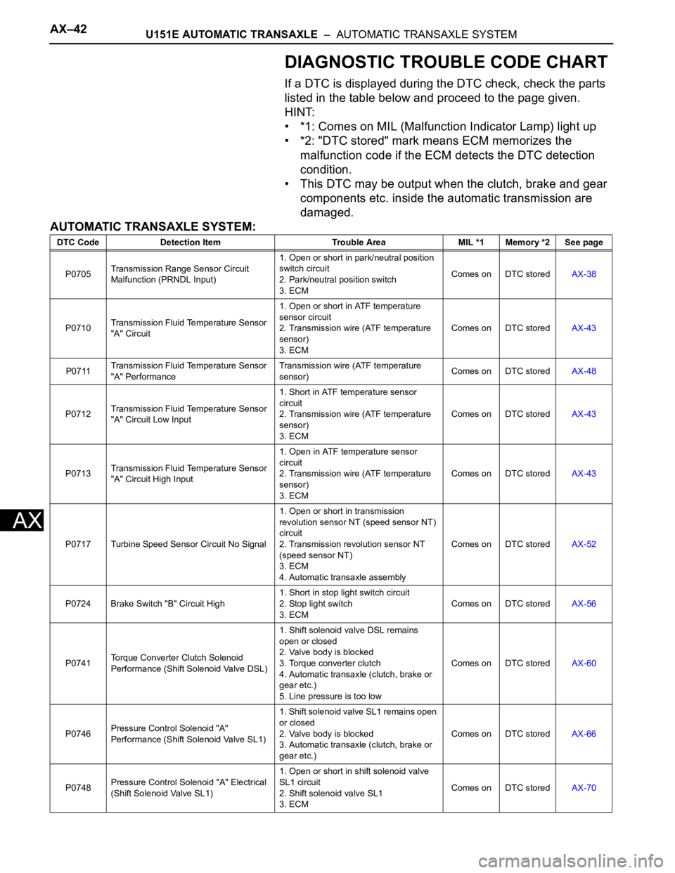
DIAGNOSTIC TROUBLE CODE CHART
If a DTC is displayed during the DTC check, check the parts
listed in the table below and proceed to the page given.
HINT:
• *1: Comes on MIL (Malfunction Indicator Lamp) light up
• *2: "DTC stored" mark means ECM memorizes the
malfunction code if the ECM detects the DTC detection
condition.
• This DTC may be output when the clutch, brake and gear
components etc. inside the automatic transmission are
damaged.
AUTOMATIC TRANSAXLE SYSTEM:
DTC Code Detection Item Trouble Area MIL *1 Memory *2 See page
P0705Transmission Range Sensor Circuit
Malfunction (PRNDL Input)1. Open or short in park/neutral position
switch circuit
2. Park/neutral position switch
3. ECMComes on DTC storedAX-38
P0710Transmission Fluid Temperature Sensor
"A" Circuit1. Open or short in ATF temperature
sensor circuit
2. Transmission wire (ATF temperature
sensor)
3. ECMComes on DTC storedAX-43
P0711Transmission Fluid Temperature Sensor
"A" PerformanceTransmission wire (ATF temperature
sensor)Comes on DTC storedAX-48
P0712Transmission Fluid Temperature Sensor
"A" Circuit Low Input1. Short in ATF temperature sensor
circuit
2. Transmission wire (ATF temperature
sensor)
3. ECMComes on DTC storedAX-43
P0713Transmission Fluid Temperature Sensor
"A" Circuit High Input1. Open in ATF temperature sensor
circuit
2. Transmission wire (ATF temperature
sensor)
3. ECMComes on DTC storedAX-43
P0717 Turbine Speed Sensor Circuit No Signal1. Open or short in transmission
revolution sensor NT (speed sensor NT)
circuit
2. Transmission revolution sensor NT
(speed sensor NT)
3. ECM
4. Automatic transaxle assemblyComes on DTC storedAX-52
P0724 Brake Switch "B" Circuit High1. Short in stop light switch circuit
2. Stop light switch
3. ECMComes on DTC storedAX-56
P0741Torque Converter Clutch Solenoid
Performance (Shift Solenoid Valve DSL)1. Shift solenoid valve DSL remains
open or closed
2. Valve body is blocked
3. Torque converter clutch
4. Automatic transaxle (clutch, brake or
gear etc.)
5. Line pressure is too lowComes on DTC storedAX-60
P0746Pressure Control Solenoid "A"
Performance (Shift Solenoid Valve SL1)1. Shift solenoid valve SL1 remains open
or closed
2. Valve body is blocked
3. Automatic transaxle (clutch, brake or
gear etc.)Comes on DTC storedAX-66
P0748Pressure Control Solenoid "A" Electrical
(Shift Solenoid Valve SL1)1. Open or short in shift solenoid valve
SL1 circuit
2. Shift solenoid valve SL1
3. ECMComes on DTC storedAX-70
Page 1409 of 3000

U151E AUTOMATIC TRANSAXLE – AUTOMATIC TRANSAXLE SYSTEMAX–43
AX
P0766Shift Solenoid "D" Performance (Shift
Solenoid Valve S4)1. Shift solenoid valve S4 remains open
or closed
2. Valve body is blocked (Brake control
valve)
3. Automatic transaxle (clutch, brake or
gear, etc.)Comes on DTC storedAX-74
P0771Shift Solenoid "E" Performance (Shift
Solenoid Valve SR)1. Shift solenoid valve SR remains open
or closed
2. Valve body is blocked
3. Automatic transaxle (clutch, brake or
gear etc.)Comes on DTC storedAX-78
P0776Pressure Control Solenoid "B"
Performance (Shift Solenoid Valve SL2)1. Shift solenoid valve SL2 remains open
or closed
2. Valve body is blocked
3. Automatic transaxle (clutch, brake or
gear etc.)Comes on DTC storedAX-82
P0778Pressure Control Solenoid "B" Electrical
(Shift Solenoid Valve SL2)1. Open or short in shift solenoid valve
SL2 circuit
2. Shift solenoid valve SL2
3. ECMComes on DTC storedAX-87
P0793 Intermediate Shaft Speed Sensor "A"1. Open or short in transmission
revolution sensor NC (speed sensor NC)
circuit
2. Transmission revolution sensor NC
(speed sensor NC)
3. ECMComes on DTC storedAX-91
P0796Pressure Control Solenoid "C"
Performance (Shift Solenoid Valve SL3)1. Shift solenoid valve SL3 remains open
or closed
2. Valve body is blocked
3. Automatic transaxle (clutch, brake or
gear etc.)Comes on DTC storedAX-95
P0798Pressure Control Solenoid "C" Electrical
(Shift Solenoid Valve SL3)1. Open or short in shift solenoid valve
SL3 circuit
2. Shift solenoid valve SL3
3. ECMComes on DTC storedAX-100
P0982Shift Solenoid "D" Control Circuit Low
(Shift Solenoid Valve S4)1. Short in shift solenoid valve S4 circuit
2. Shift solenoid valve S4
3. ECMComes on DTC storedAX-104
P0983Shift Solenoid "D" Control Circuit High
(Shift Solenoid Valve S4)1. Open in shift solenoid valve S4 circuit
2. Shift solenoid valve S4
3. ECMComes on DTC storedAX-104
P0985Shift Solenoid "E" Control Circuit Low
(Shift Solenoid Valve SR)1. Short in shift solenoid valve SR circuit
2. Shift solenoid valve SR
3. ECMComes on DTC storedAX-107
P0986Shift Solenoid "E" Control Circuit High
(Shift Solenoid Valve SR)1. Open in shift solenoid valve SR circuit
2. Shift solenoid valve SR
3. ECMComes on DTC storedAX-107
P2714Pressure Control Solenoid "D"
Performance (Shift Solenoid Valve SLT)1. Shift solenoid valve SLT remains
closed
2. Valve body is blocked
3. Automatic transaxle (clutch, brake or
gear etc.)Comes on DTC stored
AX-110
P2716Pressure Control Solenoid "D" Electrical
(Shift Solenoid Valve SLT)1. Open or short in shift solenoid valve
SLT circuit
2. Shift solenoid valve SLT
3. ECMComes on DTC storedAX-116
P2769Torque Converter Clutch Solenoid Circuit
Low (Shift Solenoid Valve DSL)1. Short in shift solenoid valve DSL
circuit
2. Shift solenoid valve DSL
3. ECMComes on DTC storedAX-120 DTC Code Detection Item Trouble Area MIL *1 Memory *2 See page
Page 1411 of 3000

U151E AUTOMATIC TRANSAXLE – AUTOMATIC TRANSAXLE SYSTEMAX–45
AX
DESCRIPTION
The park/neutral position switch detects the shift lever position and sends signals to the ECM.
MONITOR DESCRIPTION
These DTCs indicate a problem with the park/neutral position switch and the wire harness in the park/
neutral position switch circuit.
The park/neutral position switch detects the shift lever position and sends a signal to the ECM.
For security, the park/neutral position switch detects the shift lever position so that engine can be started
only when the shift lever is in the P or N position
The park/neutral position switch sends a signal to the ECM according to the shift position (P, R, N or D).
The ECM determines that there is a problem with the switch or related parts if in receives more than 1
position signal simultaneously. The ECM will turn on the MIL and store the DTC.
MONITOR STRATEGY
DTC P0705Transmission Range Sensor Circuit Malfunc-
tion (PRNDL Input)
DTC No. DTC Detection Condition Trouble Area
P0705(A) Any 2 or more signals of the following are ON
simultaneously (2-trip detection logic)
• P input signal is ON.
• N input signal is ON.
• R input signal is ON.
• D input signal is ON.
• 3 input signal is ON.
• 2 input signal is ON.
(B) Any 2 or more signals of the following are ON
simultaneously (2-trip detection logic)
• NSW (STAR) input signal is ON.
• R input signal is ON.
• D input signal is ON.
• 3 input signal is ON.
• 2 input signal is ON.
(C) All switches are OFF simultaneously for NSW
(STAR), P, R, N, D, 3, 2 positions (2-trip detection
logic).
(D) Both 1 and 2 conditions are met (2-trip detection
logic)
1. One of the following conditions are met
(a) NSW (STAR) input signal is ON.
(b) P input signal is ON.
(c) N input signal is ON.
(d) R input signal is ON.
2. One of the following conditions are met
(a) 4 input signal is ON.
(b) L input signal is ON.• Short in park/neutral position switch circuit
• Park/neutral position switch
•ECM
Related DTCs P0705: Park/neutral position switch/Verify switch input
Required sensors/Components Park/neutral position switch
Frequency of operation Continuous
DurationCondition (A), (B), (D)
2 sec.
Condition (C)
60 sec.
MIL operation 2 driving cycles
Sequence of operation None
Page 1414 of 3000
AX–48U151E AUTOMATIC TRANSAXLE – AUTOMATIC TRANSAXLE SYSTEM
AX
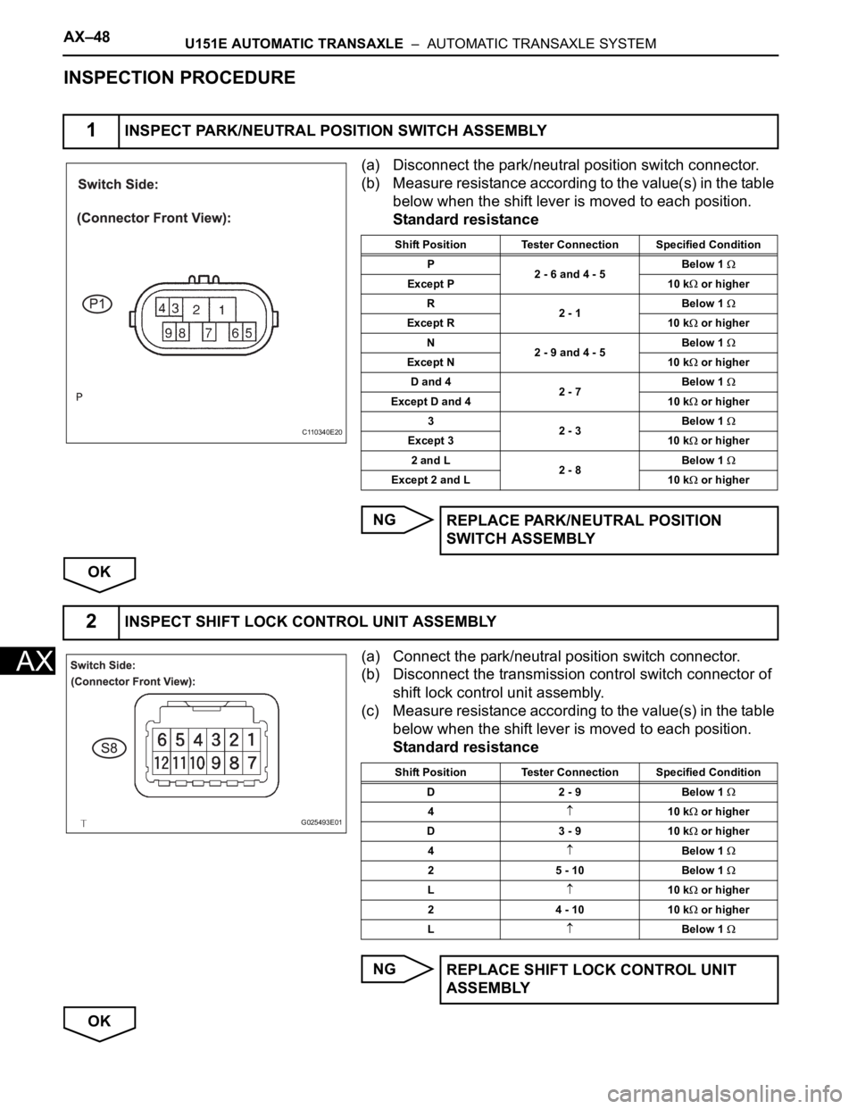
INSPECTION PROCEDURE
(a) Disconnect the park/neutral position switch connector.
(b) Measure resistance according to the value(s) in the table
below when the shift lever is moved to each position.
Standard resistance
NG
OK
(a) Connect the park/neutral position switch connector.
(b) Disconnect the transmission control switch connector of
shift lock control unit assembly.
(c) Measure resistance according to the value(s) in the table
below when the shift lever is moved to each position.
Standard resistance
NG
OK
1INSPECT PARK/NEUTRAL POSITION SWITCH ASSEMBLY
C110340E20
Shift Position Tester Connection Specified Condition
P
2 - 6 and 4 - 5Below 1
Except P 10 k or higher
R
2 - 1Below 1
Except R 10 k or higher
N
2 - 9 and 4 - 5Below 1
Except N 10 k or higher
D and 4
2 - 7Below 1
Except D and 4 10 k or higher
3
2 - 3Below 1
Except 3 10 k or higher
2 and L
2 - 8Below 1
Except 2 and L 10 k or higher
REPLACE PARK/NEUTRAL POSITION
SWITCH ASSEMBLY
2INSPECT SHIFT LOCK CONTROL UNIT ASSEMBLY
G025493E01
Shift Position Tester Connection Specified Condition
D 2 - 9 Below 1
410 k or higher
D 3 - 9 10 k
or higher
4
Below 1
2 5 - 10 Below 1
L10 k or higher
2 4 - 10 10 k
or higher
L
Below 1
REPLACE SHIFT LOCK CONTROL UNIT
ASSEMBLY
Page 1415 of 3000
U151E AUTOMATIC TRANSAXLE – AUTOMATIC TRANSAXLE SYSTEMAX–49
AX
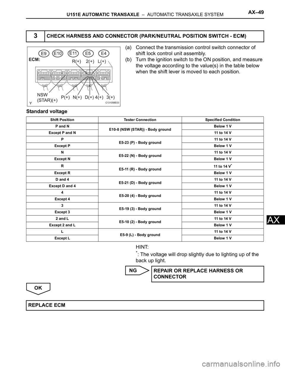
(a) Connect the transmission control switch connector of
shift lock control unit assembly.
(b) Turn the ignition switch to the ON position, and measure
the voltage according to the value(s) in the table below
when the shift lever is moved to each position.
Standard voltage
HINT:
*: The voltage will drop slightly due to lighting up of the
back up light.
NG
OK
3CHECK HARNESS AND CONNECTOR (PARK/NEUTRAL POSITION SWITCH - ECM)
C131058E03
Shift Position Tester Connection Specified Condition
P and N
E10-8 (NSW (STAR)) - Body groundBelow 1 V
Except P and N11 to 14 V
P
E5-23 (P) - Body ground11 to 14 V
Except PBelow 1 V
N
E5-22 (N) - Body ground11 to 14 V
Except NBelow 1 V
R
E5-11 (R) - Body ground11 to 14 V
*
Except RBelow 1 V
D and 4
E5-21 (D) - Body ground11 to 14 V
Except D and 4Below 1 V
4
E5-20 (4) - Body ground11 to 14 V
Except 4Below 1 V
3
E5-19 (3) - Body ground11 to 14 V
Except 3Below 1 V
2 and L
E5-10 (2) - Body ground11 to 14 V
Except 2 and LBelow 1 V
L
E5-9 (L) - Body ground11 to 14 V
Except LBelow 1 V
REPAIR OR REPLACE HARNESS OR
CONNECTOR
REPLACE ECM
Page 1416 of 3000
AX–50U151E AUTOMATIC TRANSAXLE – AUTOMATIC TRANSAXLE SYSTEM
AX
DESCRIPTION
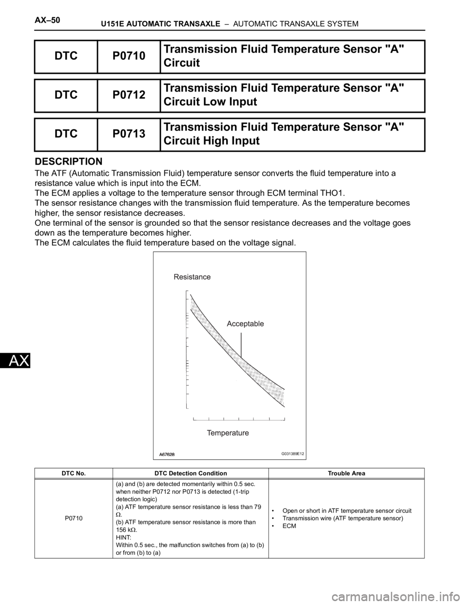
The ATF (Automatic Transmission Fluid) temperature sensor converts the fluid temperature into a
resistance value which is input into the ECM.
The ECM applies a voltage to the temperature sensor through ECM terminal THO1.
The sensor resistance changes with the transmission fluid temperature. As the temperature becomes
higher, the sensor resistance decreases.
One terminal of the sensor is grounded so that the sensor resistance decreases and the voltage goes
down as the temperature becomes higher.
The ECM calculates the fluid temperature based on the voltage signal.
DTC P0710Transmission Fluid Temperature Sensor "A"
Circuit
DTC P0712Transmission Fluid Temperature Sensor "A"
Circuit Low Input
DTC P0713Transmission Fluid Temperature Sensor "A"
Circuit High Input
DTC No. DTC Detection Condition Trouble Area
P0710(a) and (b) are detected momentarily within 0.5 sec.
when neither P0712 nor P0713 is detected (1-trip
detection logic)
(a) ATF temperature sensor resistance is less than 79
.
(b) ATF temperature sensor resistance is more than
156 k
.
HINT:
Within 0.5 sec., the malfunction switches from (a) to (b)
or from (b) to (a)• Open or short in ATF temperature sensor circuit
• Transmission wire (ATF temperature sensor)
•ECM
G031389E12