Page 1505 of 3000
U151E AUTOMATIC TRANSAXLE – PARK / NEUTRAL POSITION SWITCHAX–125
AX
REMOVAL
1. REMOVE BATTERY
2. REMOVE AIR CLEANER ASSEMBLY
HINT:
(See page EM-26)
3. SEPARATE TRANSMISSION CONTROL CABLE
ASSEMBLY
(a) Remove the nut from the control shaft lever.
(b) Disconnect the control cable from the control shaft
lever.
(c) Remove the clip and disconnect the control cable
from the control cable bracket.
NOTICE:
Do not hold the resin guide pipe.
4. REMOVE PARK/NEUTRAL POSITION SWITCH
ASSEMBLY
(a) Disconnect the park/neutral position switch
connector.
(b) Remove the nut, washer and control shaft lever.
D030614
D025415
C092283
C099458
Page 1509 of 3000
U151E AUTOMATIC TRANSAXLE – PARK / NEUTRAL POSITION SWITCHAX–129
AX
(j) Install the control shaft lever, washer and the nut.
Torque: 13 N*m (130 kgf*cm, 9 ft.*lbf)
(k) Connect the park/neutral position switch connector.
2. CONNECT TRANSMISSION CONTROL CABLE
ASSEMBLY
(a) Connect the control cable to the control shaft lever
with the nut.
Torque: 13 N*m (133 kgf*cm, 10 ft.*lbf)
(b) Install the control cable with a new clip to the
bracket.
3. ADJUST PARK/NEUTRAL POSITION SWITCH
ASSEMBLY (See page AX-127)
4. INSPECT PARK/NEUTRAL POSITION SWITCH
ASSEMBLY OPERATION (See page AX-126)
5. INSPECT SHIFT LEVER POSITION (See page AX-148)
6. ADJUST SHIFT LEVER POSITION (See page AX-149)
7. INSTALL AIR CLEANER ASSEMBLY
HINT:
(See page EM-44)
8. INSTALL BATTERY
C099458
C092283
D030614
D025415
Page 1510 of 3000

U151E AUTOMATIC TRANSAXLE – AUTOMATIC TRANSAXLE SYSTEMAX–17
AX
MANUAL SHIFTING TEST
1. PERFORM MANUAL SHIFTING TEST
HINT:
• With this test, it can be determined whether the
trouble occurs in the electrical circuit or is a
mechanical problem in the transaxle.
• If any abnormalities are found in the following test, the
problem is in the transaxle itself.
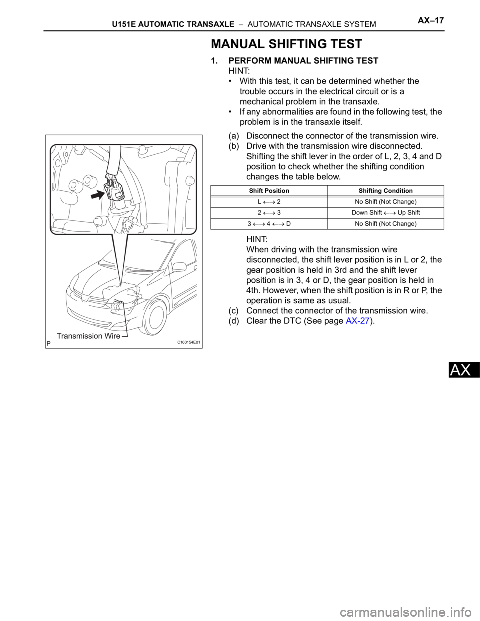
(a) Disconnect the connector of the transmission wire.
(b) Drive with the transmission wire disconnected.
Shifting the shift lever in the order of L, 2, 3, 4 and D
position to check whether the shifting condition
changes the table below.
HINT:
When driving with the transmission wire
disconnected, the shift lever position is in L or 2, the
gear position is held in 3rd and the shift lever
position is in 3, 4 or D, the gear position is held in
4th. However, when the shift position is in R or P, the
operation is same as usual.
(c) Connect the connector of the transmission wire.
(d) Clear the DTC (See page AX-27).
C160154E01
Shift Position Shifting Condition
L
2 No Shift (Not Change)
2
3 Down Shift Up Shift
3
4 D No Shift (Not Change)
Page 1513 of 3000
AX–130U151E AUTOMATIC TRANSAXLE – TRANSMISSION WIRE
AX
TRANSMISSION
U151E AUTOMATIC TRANSAXLE
TRANSMISSION WIRE
COMPONENTS
C119004E05
Page 1514 of 3000

U151E AUTOMATIC TRANSAXLE – TRANSMISSION WIREAX–131
AX
REMOVAL
1. DISCONNECT CABLE FROM NEGATIVE BATTERY
TERMINAL
2. REMOVE ENGINE UNDER COVER NO.1
3. DRAIN AUTOMATIC TRANSAXLE FLUID
(a) Remove the drain plug and gasket, and drain the
AT F.
(b) Install a new gasket and the drain plug.
Torque: 49 N*m (500 kgf*cm, 36 ft.*lbf)
4. REMOVE AUTOMATIC TRANSAXLE OIL PAN SUB-
ASSEMBLY
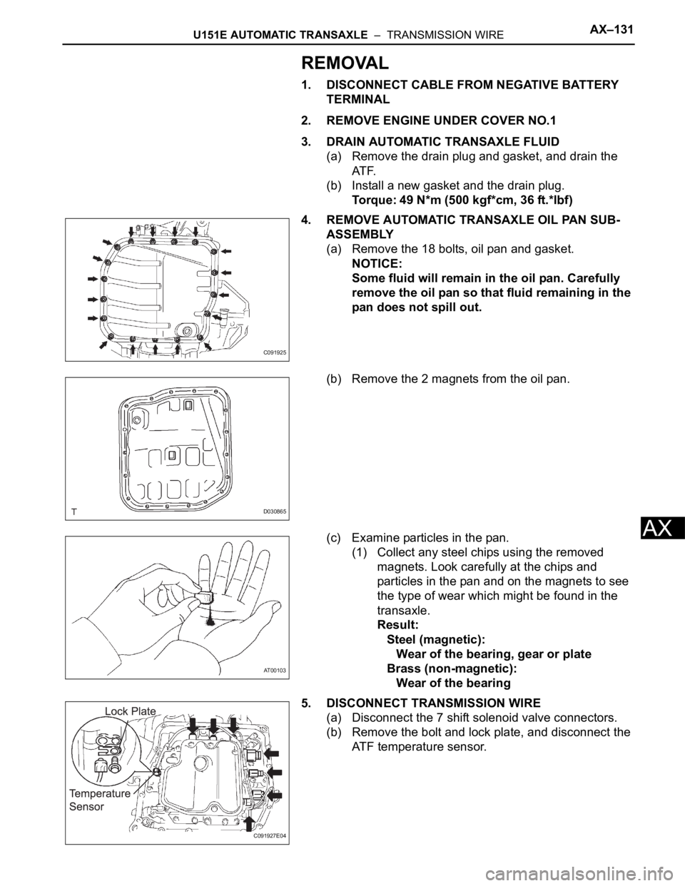
(a) Remove the 18 bolts, oil pan and gasket.
NOTICE:
Some fluid will remain in the oil pan. Carefully
remove the oil pan so that fluid remaining in the
pan does not spill out.
(b) Remove the 2 magnets from the oil pan.
(c) Examine particles in the pan.
(1) Collect any steel chips using the removed
magnets. Look carefully at the chips and
particles in the pan and on the magnets to see
the type of wear which might be found in the
transaxle.
Result:
Steel (magnetic):
Wear of the bearing, gear or plate
Brass (non-magnetic):
Wear of the bearing
5. DISCONNECT TRANSMISSION WIRE
(a) Disconnect the 7 shift solenoid valve connectors.
(b) Remove the bolt and lock plate, and disconnect the
ATF temperature sensor.
C091925
D030865
AT00103
C091927E04
Page 1515 of 3000
AX–132U151E AUTOMATIC TRANSAXLE – TRANSMISSION WIRE
AX
6. REMOVE TRANSMISSION WIRE
(a) Disconnect the transmission wire connector.
(b) Remove the bolt and transmission wire.
(c) Remove the O-ring from the transmission wire.
INSTALLATION
1. INSTALL TRANSMISSION WIRE
(a) Coat the O-ring of the transmission wire connector
with ATF and install it.
(b) Install the transmission wire with the bolt.
Torque: 5.4 N*m (55 kgf*cm, 48 ft.*lbf)
2. CONNECT TRANSMISSION WIRE
(a) Coat the O-ring of the ATF temperature sensor with
AT F.
(b) Install the ATF temperature sensor with the lock
plate and bolt.
Torque: 6.6 N*m (67 kgf*cm, 58 ft.*lbf)
(c) Connect the 7 shift solenoid valve connectors.
3. INSTALL AUTOMATIC TRANSAXLE OIL PAN SUB-
ASSEMBLY
(a) Install the 2 magnets in the oil pan.
(b) Apply seal packing to the 18 bolts.
Seal packing:
THREE BOND 2430 or equivalent
D030866
D030867
D030866
C091927E04
D030865
Page 1516 of 3000
U151E AUTOMATIC TRANSAXLE – TRANSMISSION WIREAX–133
AX
(c) Using a new gasket, install the oil pan to the
transaxle case with the 18 bolts.
Torque: 7.8 N*m (80 kgf*cm, 69 in.*lbf)
NOTICE:
Apply seal packing to the bolts and tighten them
within 10 minutes of application.
4. CONNECT CABLE TO NEGATIVE BATTERY
TERMINAL
5. ADD AUTOMATIC TRANSAXLE FLUID
6. INSPECT AUTOMATIC TRANSAXLE FLUID (See page
AX-123)
7. INSTALL ENGINE UNDER COVER NO.1
8. RESET MEMORY
HINT:
(See page AX-16)
C091925
Page 1519 of 3000

AX–136U151E AUTOMATIC TRANSAXLE – VALVE BODY ASSEMBLY
AX
REMOVAL
1. REMOVE ENGINE UNDER COVER NO.1
2. DISCONNECT CABLE FROM NEGATIVE BATTERY
TERMINAL
3. DRAIN AUTOMATIC TRANSAXLE FLUID (See page
AX-131)
4. REMOVE AUTOMATIC TRANSAXLE OIL PAN SUB-
ASSEMBLY
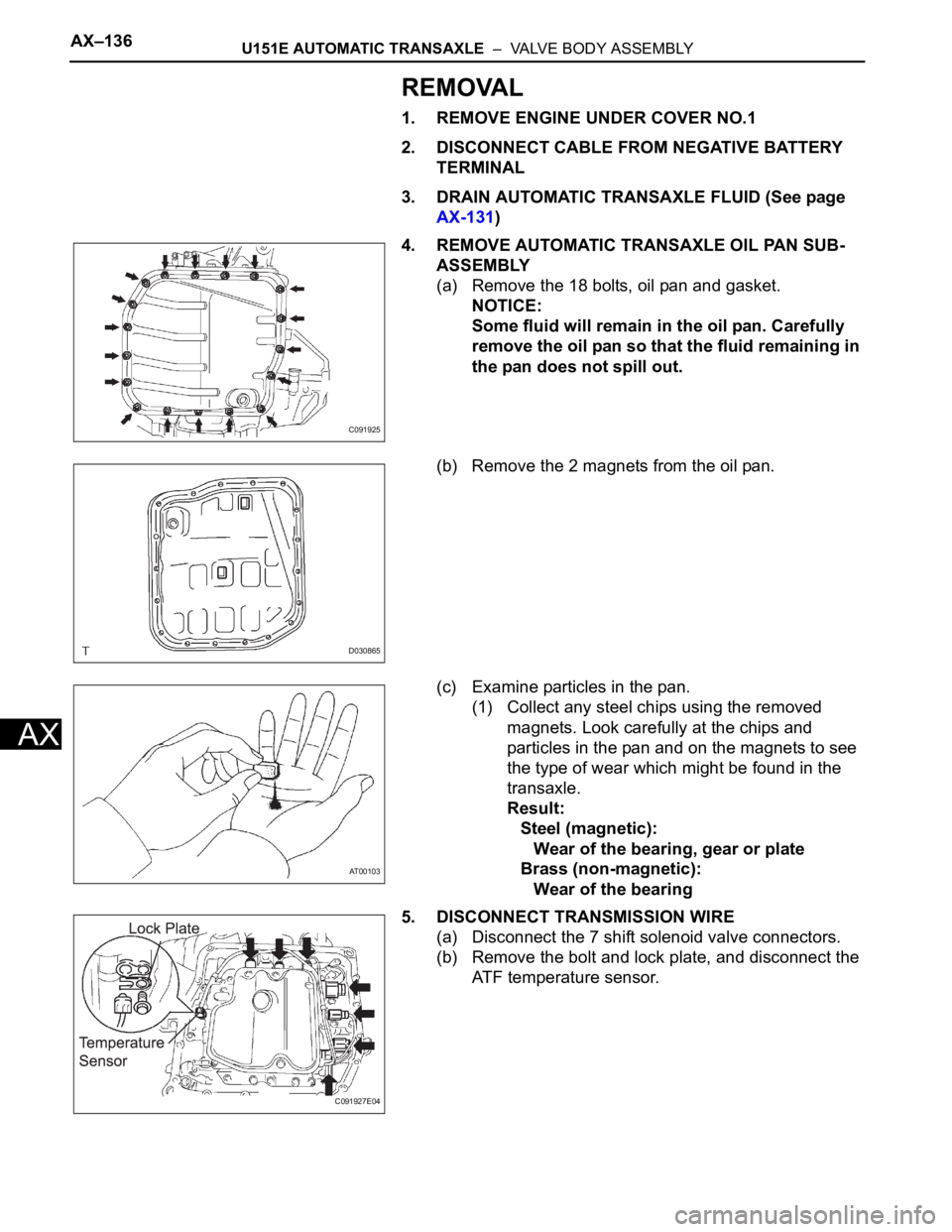
(a) Remove the 18 bolts, oil pan and gasket.
NOTICE:
Some fluid will remain in the oil pan. Carefully
remove the oil pan so that the fluid remaining in
the pan does not spill out.
(b) Remove the 2 magnets from the oil pan.
(c) Examine particles in the pan.
(1) Collect any steel chips using the removed
magnets. Look carefully at the chips and
particles in the pan and on the magnets to see
the type of wear which might be found in the
transaxle.
Result:
Steel (magnetic):
Wear of the bearing, gear or plate
Brass (non-magnetic):
Wear of the bearing
5. DISCONNECT TRANSMISSION WIRE
(a) Disconnect the 7 shift solenoid valve connectors.
(b) Remove the bolt and lock plate, and disconnect the
ATF temperature sensor.
C091925
D030865
AT00103
C091927E04