Page 1546 of 3000
AX–154U151E AUTOMATIC TRANSAXLE – TRANSMISSION CONTROL CABLE ASSEMBLY
AX
REMOVAL
1. DISCONNECT BATTERY NEGATIVE TERMINAL
2. REMOVE INSTRUMENT CLUSTER FINISH PANEL
SUB-ASSEMBLY CENTER
HINT:
(See page IP-9)
3. REMOVE TRANSMISSION CONTROL CABLE
ASSEMBLY
(a) Remove the nut from the control shaft lever.
(b) Disconnect the transmission control cable assembly
from the control shaft lever.
(c) Remove the clip and disconnect the transmission
control cable assembly from the control cable
bracket.
(d) Disconnect the transmission control cable assembly
from the transmission control cable bracket No.2.
(e) Remove the 2 nuts and disconnect the transmission
control cable assembly from the vehicle.
D025414E06
D025415E01
D025416E01
C086313E01
Page 1547 of 3000
U151E AUTOMATIC TRANSAXLE – TRANSMISSION CONTROL CABLE ASSEMBLYAX–155
AX
(f) Using a screwdriver, disconnect the cable end from
the shift lever assembly
(g) Using a small screwdriver, disconnect the cable
outer of transmission control cable assembly from
the shift lever assembly.
(h) Pull out the control cable from the vehicle.
C086305E02
Page 1548 of 3000

AX–156U151E AUTOMATIC TRANSAXLE – TRANSMISSION CONTROL CABLE ASSEMBLY
AX
ADJUSTMENT
1. INSPECT SHIFT LEVER POSITION
(a) When shifting from P to R position only with ignition
switch ON and brake pedal, make sure that the
shifting lever moves smoothly and can be
moderately operated.
(b) When starting engine, make sure that the vehicle
moves forward when shifting from N to D position
and moves rearward when shifting to R position.
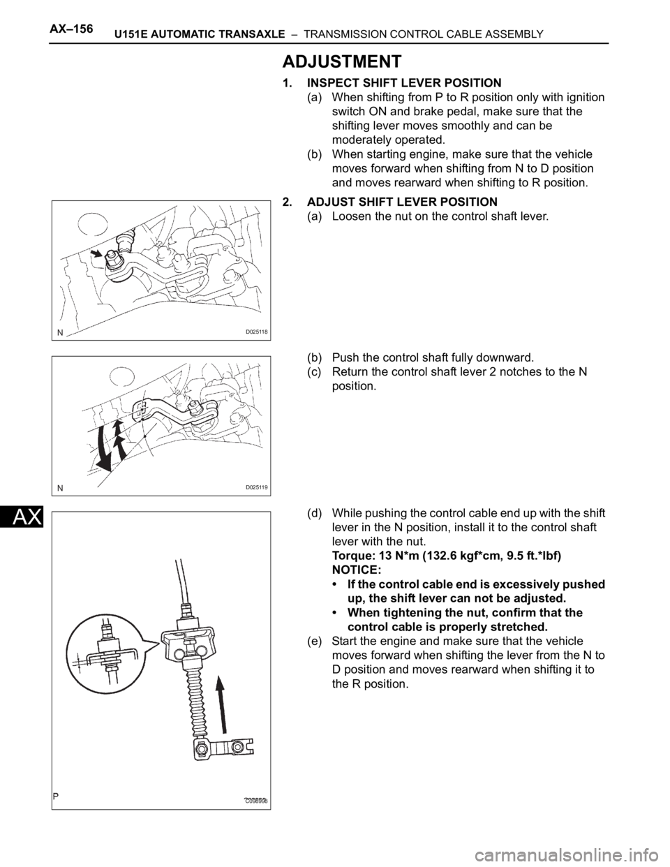
2. ADJUST SHIFT LEVER POSITION
(a) Loosen the nut on the control shaft lever.
(b) Push the control shaft fully downward.
(c) Return the control shaft lever 2 notches to the N
position.
(d) While pushing the control cable end up with the shift
lever in the N position, install it to the control shaft
lever with the nut.
Torque: 13 N*m (132.6 kgf*cm, 9.5 ft.*lbf)
NOTICE:
• If the control cable end is excessively pushed
up, the shift lever can not be adjusted.
• When tightening the nut, confirm that the
control cable is properly stretched.
(e) Start the engine and make sure that the vehicle
moves forward when shifting the lever from the N to
D position and moves rearward when shifting it to
the R position.
D025118
D025119
C098998
Page 1549 of 3000
U151E AUTOMATIC TRANSAXLE – TRANSMISSION CONTROL CABLE ASSEMBLYAX–157
AX
INSTALLATION
1. INSTALL TRANSMISSION CONTROL CABLE
ASSEMBLY
(a) Pull in the control cable to the body.
(b) Install the cable end, as shown in the illustration.
(c) When installing the transmission control cable
assembly on the shift lever plate, place the
projection of the shift cable downward to fit in the
groove of the shift lever plate (FIG.2)
Confirm that the spring in the shift cable outer has
moved to the position (FIG.3) shown in the
illustration.
Confirm that the shift cable is installed on the shift
lever plate properly.
NOTICE:
• To prevent torsion of the inner cable, the
projection on the eye end should face rear.
• Push the cable end to the bottom of the pin.
(d) Install the transmission control cable assembly and
2 nuts.
Torque: 12 N*m (122 kgf*cm, 9 ft.*lbf)
C086312E01
D030843E01
C086313E02
Page 1550 of 3000
AX–158U151E AUTOMATIC TRANSAXLE – TRANSMISSION CONTROL CABLE ASSEMBLY
AX
(e) Connect the transmission control cable assembly to
the transmission control cable bracket No.2.
(f) Temporarily install the transmission control cable
assembly to the control shaft lever with the nut.
(g) Install the transmission control cable assembly and
clip to the bracket.
2. INSTALL INSTRUMENT CLUSTER FINISH PANEL
SUB-ASSEMBLY CENTER
HINT:
(See page IP-15)
3. ADJUST SHIFT LEVER POSITION
HINT:
(See page AX-155)
4. INSPECT SHIFT LEVER POSITION
HINT:
(See page AX-155)
D025416E02
D025415E02
D025414E07
Page 1553 of 3000
AX–158U151E AUTOMATIC TRANSAXLE – DIFFERENTIAL OIL SEAL
AX
TRANSMISSION
U151E AUTOMATIC TRANSAXLE
DIFFERENTIAL OIL SEAL
COMPONENTS
C126455E01
Page 1558 of 3000
U151E AUTOMATIC TRANSAXLE – AUTOMATIC TRANSAXLE UNITAX–179
AX
9. INSPECT TRANSMISSION OIL CLEANER MAGNET
(a) Remove the magnets and use them to collect any
steel chips. Examine the chips and particles in the
pan and on the magnet to determine what type of
wear has occurred in the transaxle:
Result:
Steel (magnetic):
Wear of the bearing, gear and plate
Brass (non-magnetic):
Wear of the bushing
10. DISCONNECT TRANSMISSION WIRE
(a) Remove the 7 connectors from the shift solenoid
valves.
(b) Remove the bolt, lock plate and temperature
sensor.
11. REMOVE TRANSMISSION WIRE
(a) Remove the bolt and transmission wire from the
transaxle case.
12. REMOVE VALVE BODY OIL STRAINER ASSEMBLY
(a) Remove the 3 bolts and oil strainer.
(b) Remove the O-ring from the oil strainer.
AT00103E03
C091927E02
D003547E05
C091931
C091932E01
Page 1559 of 3000
AX–180U151E AUTOMATIC TRANSAXLE – AUTOMATIC TRANSAXLE UNIT
AX
13. REMOVE TRANSMISSION VALVE BODY ASSEMBLY
(a) Support the valve body assembly and remove the
17 bolts and valve body assembly.
14. REMOVE GOVERNOR APPLY GASKET NO.1
(a) Remove the governor apply gasket No.1 from the
transaxle case.
15. REMOVE TRANSAXLE CASE 2ND BRAKE GASKET
(a) Remove the transaxle case 2nd brake gasket from
the transaxle case.
16. REMOVE BRAKE DRUM GASKET
(a) Remove the brake drum gasket from the transaxle
case.
17. REMOVE CHECK BALL BODY
(a) Remove the check ball body and spring from the
transaxle case.
C091933
C083127
C083128
C083129
D003554E01