Page 1520 of 3000
U151E AUTOMATIC TRANSAXLE – VALVE BODY ASSEMBLYAX–137
AX
6. REMOVE VALVE BODY OIL STRAINER ASSEMBLY
(a) Remove the 3 bolts and oil strainer.
NOTICE:
Be careful when removing the oil strainer as
fluid will come out.
(b) Remove the O-ring from the valve body oil strainer
assembly.
7. REMOVE TRANSMISSION VALVE BODY ASSEMBLY
(a) Support the valve body assembly and remove the
17 bolts and the transmission valve body assembly.
(b) Remove the check ball body and the spring.
(c) Remove the bolt and lock plate from the valve body
assembly.
(d) Remove the shift solenoid valve SL3 and SLT from
the valve body assembly.
C091931
C091932
C091933
C050017
C089112
Page 1522 of 3000
U151E AUTOMATIC TRANSAXLE – VALVE BODY ASSEMBLYAX–139
AX
INSTALLATION
1. INSTALL TRANSMISSION VALVE BODY ASSEMBLY
(a) Install the shift solenoid valve SL1 to the valve body
assembly with the bolt.
Torque: 6.6 N*m (67 kgf*cm, 58 in.*lbf)
(b) Install the shift solenoid valve SL2 to the valve body
assembly with the bolt.
Torque: 11 N*m (110 kgf*cm, 8 ft.*lbf)
(c) Install the shift solenoid valve DSL to the valve body
assembly with the bolt.
Torque: 11 N*m (110 kgf*cm, 8 ft.*lbf)
(d) Install the shift solenoid valve SR to the valve body
assembly.
(e) Install the shift solenoid valve S4 to the valve body
assembly with the bolt.
Torque: 11 N*m (110 kgf*cm, 8 ft.*lbf)
C089115
C089113
D026443
D026438
D026442
Page 1524 of 3000

U151E AUTOMATIC TRANSAXLE – VALVE BODY ASSEMBLYAX–141
AX
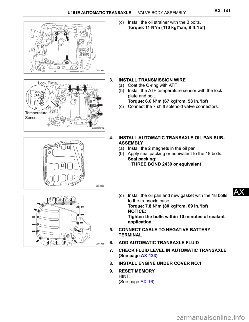
(c) Install the oil strainer with the 3 bolts.
Torque: 11 N*m (110 kgf*cm, 8 ft.*lbf)
3. INSTALL TRANSMISSION WIRE
(a) Coat the O-ring with ATF.
(b) Install the ATF temperature sensor with the lock
plate and bolt.
Torque: 6.6 N*m (67 kgf*cm, 58 in.*lbf)
(c) Connect the 7 shift solenoid valve connectors.
4. INSTALL AUTOMATIC TRANSAXLE OIL PAN SUB-
ASSEMBLY
(a) Install the 2 magnets in the oil pan.
(b) Apply seal packing or equivalent to the 18 bolts.
Seal packing:
THREE BOND 2430 or equivalent
(c) Install the oil pan and new gasket with the 18 bolts
to the transaxle case.
Torque: 7.8 N*m (80 kgf*cm, 69 in.*lbf)
NOTICE:
Tighten the bolts within 10 minutes of sealant
application.
5. CONNECT CABLE TO NEGATIVE BATTERY
TERMINAL
6. ADD AUTOMATIC TRANSAXLE FLUID
7. CHECK FLUID LEVEL IN AUTOMATIC TRANSAXLE
(See page AX-123)
8. INSTALL ENGINE UNDER COVER NO.1
9. RESET MEMORY
HINT:
(See page AX-16)
C091931
C091927E04
D030865
C091925
Page 1525 of 3000

AX–22U151E AUTOMATIC TRANSAXLE – AUTOMATIC TRANSAXLE SYSTEM
AX
PROBLEM SYMPTOMS TABLE
HINT:
• If a normal code is displayed during the diagnostic trouble
code check although the trouble still occurs, check the
electrical circuits for each symptom in the order given in
the charts on the following pages and proceed to the page
given for troubleshooting.
• The Matrix Chart is divided into 2 chapters.
• When the circuit on which mark *1 is attached is a
malfunction, DTC could be output.
Refer to the table below when the trouble cause is considered
to be electrical. If the instruction PROCEED TO NEXT
CIRCUIT INSPECTION SHOWN IN PROBLEM SYMPTOMS
TABLE is given in the flowchart of each circuit, inspect the
suspected areas in descending order for each symptom. If
the trouble still occurs even though there are no
abnormalities in the inspections listed for the symptoms,
check and replace the ECM.
1. Chapter 1: Electronic Circuit Matrix Chart
Symptom Suspected Area See page
No down-shift (A particular gear, from 1st to 4th gear,
is not down-shifted)ECMIN-30
No down-shift (5th -> 4th)Transmission control switch (D <--> 4 position) circuitAX-38
Shift solenoid valve S4 circuit *1AX-104
ECMIN-30
No up-shift (A particular gear, from 1st to 4th gear, is
not up-shifted)ECMIN-30
No up-shift (4th -> 5th)Transmission control switch (D <--> 4 position) circuitAX-38
Shift solenoid valve S4 circuit *1AX-104
ECMIN-30
No lock-upStop light switch circuit *1AX-56
Engine coolant temp. sensor circuit *1ES-56
ECMIN-30
No lock-up off ECMIN-30
Shift point too high or too lowThrottle position sensor circuit *1ES-56
ECMIN-30
Up-shift to 5th from 4th while shift lever is in 4 positionTransmission control switch (D <--> 4 position) circuitAX-38
ECMIN-30
Up-shift to 5th from 4th while engine is coldEngine coolant temp. sensor circuit *1ES-56
ECMIN-30
Up-shift to 2nd from 1st while shift lever is in L positionTransmission control switch (L <--> 2 position) circuit *1AX-38
ECMIN-30
Harsh engagement (N -> D)Shift solenoid valve SL1 circuit *1AX-70
ECMIN-30
Harsh engagement (Lock-up) ECMIN-30
Harsh engagement (Any driving position) ECMIN-30
Poor acceleration ECMIN-30
No kick-down ECMIN-30
Engine stalls when starting off or stopping ECMIN-30
Malfunction in shiftingPark/neutral position switch circuit *1AX-38
Transmission control switch (D <--> 4 position) circuitAX-38
ECMIN-30
Page 1535 of 3000
U151E AUTOMATIC TRANSAXLE – SHIFT LEVERAX–147
AX
13. REMOVE SHIFT LEVER KNOB SUB-ASSEMBLY
(a) Remove the floor shift lever knob sub-assembly.
14. REMOVE POSITION INDICATOR HOUSING
ASSEMBLY
(a) Using a screwdriver, remove the position indicator
housing assembly from the instrument cluster finish
panel assembly center.
15. REMOVE INSTRUMENT CLUSTER FINISH PANEL
ASSEMBLY CENTER
HINT:
(See page IP-9)
16. REMOVE SHIFT LEVER CAP
(a) Using a small screwdriver, remove the shift lever
cap from the position indicator housing assembly.
17. REMOVE INSTRUMENT CLUSTER FINISH PANEL
SUB-ASSEMBLY LOWER CENTER
HINT:
(See page IP-9)
18. DISCONNECT TRANSMISSION CONTROL CABLE
ASSEMBLY
(a) Using a screwdriver, disconnect the cable end from
the shift lever assembly.
(b) Using a small screwdriver, disconnect the outer of
transmission control cable assembly from the shift
lever assembly.
C086302E01
C086303E01
C086304
C086305E04
Page 1540 of 3000
AX–152U151E AUTOMATIC TRANSAXLE – SHIFT LEVER
AX
2. INSTALL TRANSMISSION CONTROL CABLE
ASSEMBLY
(a) Install the cable outer to the shift lever plate
(b) When installing the transmission control cable
assembly on the shift lever plate, place the
projection to the shift lever plate (FIG. 2).
Confirm that the spring in the shift cable outer has
moved to the position (FIG. 3) shown in the
illustration.
Confirm that the shift cable is installed on the shift
lever plate properly.
NOTICE:
• To prevent torsion of the inner cable, the
projection on the eye end should face rear.
• Push the cable end to the bottom of the pin.
3. INSTALL INSTRUMENT CLUSTER FINISH PANEL
SUB-ASSEMBLY LOWER CENTER
HINT:
(See page IP-15)
4. INSTALL SHIFT LEVER CAP
(a) Install the shift lever cap to the floor shift position
indicator housing assembly.
C086312E02
D030843E02
C086304
Page 1543 of 3000

AX–30U151E AUTOMATIC TRANSAXLE – AUTOMATIC TRANSAXLE SYSTEM
AX
(g) Freeze frame data records the engine conditions
(fuel system, calculated load, engine coolant
temperature, fuel trim, engine speed, vehicle speed,
etc.) when a malfunction is detected. When
troubleshooting, freeze frame data can help
determine if the vehicle was running or stopped, if
the engine was warmed up or not, if the air/fuel ratio
was Lean or Rich, and other data from the time the
malfunction occurred.
(h) The intelligent tester records freeze frame data in
five different instance: 1) 3 times before the DTC is
set, 2) once when the DTC is set, and 3) once after
the DTC is set. These data can be used to simulate
the vehicle's condition around the time when the
malfunction occurred. The data may help find the
cause of the malfunction, or judge if the DTC is
being caused by temporary malfunction or not.
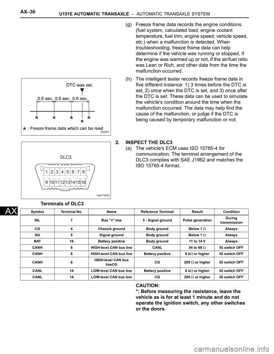
2. INSPECT THE DLC3
(a) The vehicle's ECM uses ISO 15765-4 for
communication. The terminal arrangement of the
DLC3 complies with SAE J1962 and matches the
ISO 15765-4 format.
Terminals of DLC3
CAUTION:
*: Before measuring the resistance, leave the
vehicle as is for at least 1 minute and do not
operate the ignition switch, any other switches
or the doors.
A092901
A082779E59
Symbol Terminal No. Name Reference Terminal Result Condition
SIL 7 Bus "+" line 5 - Signal ground Pulse generationDuring
transmission
CG 4 Chassis ground Body ground Below 1
Always
SG 5 Signal ground Body ground Below 1
Always
BAT 16 Battery positive Body ground 11 to 14 V Always
CANH 6 HIGH-level CAN bus line CANL 54 to 69
IG switch OFF
CANH 6 HIGH-level CAN bus line Battery positive 6 k
or higher IG switch OFF
CANH 6HIGH-level CAN bus
lineCGCG 200
or higher IG switch OFF
CANL 14 LOW-level CAN bus line Battery positive 6 k
or higher IG switch OFF
CANL 14 LOW-level CAN bus line CG 200
or higher IG switch OFF
Page 1545 of 3000
U151E AUTOMATIC TRANSAXLE – TRANSMISSION CONTROL CABLE ASSEMBLYAX–153
AX
TRANSMISSION
U151E AUTOMATIC TRANSAXLE
TRANSMISSION CONTROL CABLE ASSEMBLY
COMPONENTS
C126460E02