Page 1243 of 3000
CO–62GR-FE COOLING – COOLING FAN SYSTEM
CO
(g) After the engine is warmed up, check that the fan
operates as shown in the illustration.
HINT:
• The coolant temperature at which the fan starts
operating is approximately 95
C (203F).
• This system can also be checked using the
intelligent tester.
• Select the following menu items: Powertrain /
Engine / Data List / Initial Engine Coolant Temp.
A139339E05
Page 1253 of 3000
2GR-FE COOLING – COOLANTCO–7
CO
4. ADD ENGINE COOLANT
(a) Tighten the radiator drain cock plug by hand.
(b) Tighten the 2 cylinder block drain cock plugs.
Torque: 13 N*m (130 kgf*cm, 9 ft.*lbf) for
cylinder block drain cock plugs
(c) Remove the air drain cock plug from the water inlet
housing.
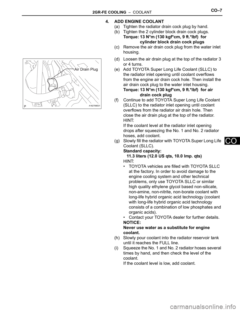
(d) Loosen the air drain plug at the top of the radiator 3
or 4 turns.
(e) Add TOYOTA Super Long Life Coolant (SLLC) to
the radiator inlet opening until coolant overflows
from the engine air drain cock hole. Then install the
air drain cock plug to the water inlet housing.
Torque: 13 N*m (130 kgf*cm, 9 ft.*lbf) for air
drain cock plug
(f) Continue to add TOYOTA Super Long Life Coolant
(SLLC) to the radiator inlet opening until coolant
overflows from the radiator air drain hole. Then
close the air drain plug at the top of the radiator.
HINT:
If the coolant level at the radiator inlet opening
drops after squeezing the No. 1 and No. 2 radiator
hoses, add coolant.
(g) Slowly fill the radiator with TOYOTA Super Long Life
Coolant (SLLC).
Standard capacity:
11.3 liters (12.0 US qts, 10.0 Imp. qts)
HINT:
• TOYOTA vehicles are filled with TOYOTA SLLC
at the factory. In order to avoid damage to the
engine cooling system and other technical
problems, only use TOYOTA SLLC or similar
high quality ethylene glycol based non-silicate,
non-amine, non-nitrite, non-borate coolant with
long-life hybrid organic acid technology (coolant
with long-life hybrid organic acid technology
consists of a combination of low phosphates and
organic acids).
• Contact your TOYOTA dealer for further details.
NOTICE:
Never use water as a substitute for engine
coolant.
(h) Slowly pour coolant into the radiator reservoir tank
until it reaches the FULL line.
(i) Squeeze the No. 1 and No. 2 radiator hoses several
times by hand, and then check the level of the
coolant.
If the coolant level is low, add coolant.
A162799E01
Page 1254 of 3000
CO–82GR-FE COOLING – COOLANT
CO
(j) Bleed air from the cooling system.
(1) Warm up the engine until the thermostat opens.
While the thermostat is open, circulate the
coolant for several minutes.
HINT:
The thermostat open timing can be confirmed
by squeezing the inlet radiator hose by hand,
and checking when the engine coolant starts to
flow inside the hose.
(2) Maintain the engine speed at 2500 to 3000
rpm.
(3) Squeeze the inlet and outlet radiator hoses
several times by hand to bleed air.
CAUTION:
When squeezing the radiator hoses:
• Wear protective gloves.
• Be careful as the radiator hoses are hot.
• Keep your hands away from the radiator
fan.
NOTICE:
• Make sure that the radiator reservoir still
has some coolant in it.
• If the coolant temperature gauge
indicates an excessive temperature, turn
off the engine and let it cool.
• If there is not enough coolant, the engine
may overheat or be seriously damaged.
• If the radiator reservoir does not have
enough coolant, perform the following: 1)
stop the engine, 2) wait until the coolant
has cooled down, and 3) add coolant
until the coolant is filled to the FULL line.
(k) Stop the engine and wait until the engine coolant
cools down.
(l) Add engine coolant to the FULL line on the radiator
reservoir.
5. INSPECT FOR COOLANT LEAK (See page CO-1)
6. INSTALL V-BANK COVER SUB-ASSEMBLY (See
page EM-63)
7. INSTALL NO. 1 ENGINE UNDER COVER (See page
EM-63)
Page 1264 of 3000
CO–462GR-FE COOLING – RADIATOR
CO
24. INSTALL BATTERY (See page EM-59)
25. INSTALL NO. 2 AIR CLEANER INLET (See page EM-
60)
26. ADD ENGINE COOLANT (See page CO-7)
27. INSPECT FOR COOLANT LEAK (See page CO-1)
28. ADD AUTOMATIC TRANSAXLE FLUID
29. CHECK AUTOMATIC TRANSAXLE FLUID (See page
AX-123)
30. INSTALL NO. 1 ENGINE UNDER COVER (See page
EM-63)
31. INSTALL V-BANK COVER SUB-ASSEMBLY (See
page EM-63)
32. VEHICLE PREPARATION FOR HEADLIGHT AIM
ADJUSTMENT (See page LI-71)
33. PREPARATION FOR HEADLIGHT AIMING (Using a
tester) (See page LI-71)
34. PREPARATION FOR HEADLIGHT AIMING (Using a
screen) (See page LI-72)
35. HEADLIGHT AIMING INSPECTION (See page LI-74)
36. HEADLIGHT AIMING ADJUSTMENT (See page LI-75)
37. VEHICLE PREPARATION FOR FOG LIGHT AIM
ADJUSTMENT (w/ Fog Light) (See page LI-82)
38. PREPARATION FOR FOG LIGHT AIMING (Using a
screen) (w/ Fog Light) (See page LI-83)
39. FOG LIGHT AIMING INSPECTION (w/ Fog Light) (See
page LI-84)
40. FOG LIGHT AIMING ADJUSTMENT (w/ Fog Light)
(See page LI-85)
Page 1291 of 3000
CO–462GR-FE COOLING – RADIATOR
CO
24. INSTALL BATTERY (See page EM-59)
25. INSTALL NO. 2 AIR CLEANER INLET (See page EM-
60)
26. ADD ENGINE COOLANT (See page CO-7)
27. INSPECT FOR COOLANT LEAK (See page CO-1)
28. ADD AUTOMATIC TRANSAXLE FLUID
29. CHECK AUTOMATIC TRANSAXLE FLUID (See page
AX-123)
30. INSTALL NO. 1 ENGINE UNDER COVER (See page
EM-63)
31. INSTALL V-BANK COVER SUB-ASSEMBLY (See
page EM-63)
32. VEHICLE PREPARATION FOR HEADLIGHT AIM
ADJUSTMENT (See page LI-71)
33. PREPARATION FOR HEADLIGHT AIMING (Using a
tester) (See page LI-71)
34. PREPARATION FOR HEADLIGHT AIMING (Using a
screen) (See page LI-72)
35. HEADLIGHT AIMING INSPECTION (See page LI-74)
36. HEADLIGHT AIMING ADJUSTMENT (See page LI-75)
37. VEHICLE PREPARATION FOR FOG LIGHT AIM
ADJUSTMENT (w/ Fog Light) (See page LI-82)
38. PREPARATION FOR FOG LIGHT AIMING (Using a
screen) (w/ Fog Light) (See page LI-83)
39. FOG LIGHT AIMING INSPECTION (w/ Fog Light) (See
page LI-84)
40. FOG LIGHT AIMING ADJUSTMENT (w/ Fog Light)
(See page LI-85)
Page 1292 of 3000
2GR-FE LUBRICATION – OIL PUMPLU–13
LU
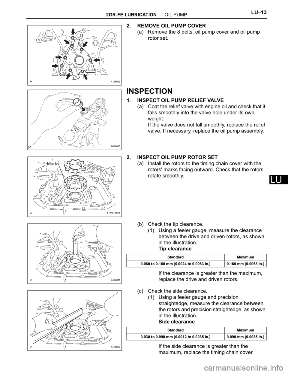
2. REMOVE OIL PUMP COVER
(a) Remove the 8 bolts, oil pump cover and oil pump
rotor set.
INSPECTION
1. INSPECT OIL PUMP RELIEF VALVE
(a) Coat the relief valve with engine oil and check that it
falls smoothly into the valve hole under its own
weight.
If the valve does not fall smoothly, replace the relief
valve. If necessary, replace the oil pump assembly.
2. INSPECT OIL PUMP ROTOR SET
(a) Install the rotors to the timing chain cover with the
rotors' marks facing outward. Check that the rotors
rotate smoothly.
(b) Check the tip clearance.
(1) Using a feeler gauge, measure the clearance
between the drive and driven rotors, as shown
in the illustration.
Tip clearance
If the clearance is greater than the maximum,
replace the drive and driven rotors.
(c) Check the side clearance.
(1) Using a feeler gauge and precision
straightedge, measure the clearance between
the rotors and precision straightedge, as shown
in the illustration.
Side clearance
If the side clearance is greater than the
maximum, replace the timing chain cover.
A128009
A094628
A128010E01
A128011
Standard Maximum
0.060 to 0.160 mm (0.0024 to 0.0063 in.) 0.160 mm (0.0063 in.)
A128012
Standard Maximum
0.030 to 0.090 mm (0.0012 to 0.0035 in.) 0.090 mm (0.0035 in.)
Page 1293 of 3000
LU–142GR-FE LUBRICATION – OIL PUMP
LU
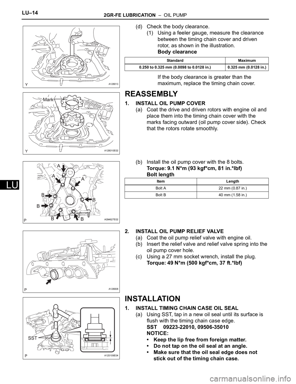
(d) Check the body clearance.
(1) Using a feeler gauge, measure the clearance
between the timing chain cover and driven
rotor, as shown in the illustration.
Body clearance
If the body clearance is greater than the
maximum, replace the timing chain cover.
REASSEMBLY
1. INSTALL OIL PUMP COVER
(a) Coat the drive and driven rotors with engine oil and
place them into the timing chain cover with the
marks facing outward (oil pump cover side). Check
that the rotors rotate smoothly.
(b) Install the oil pump cover with the 8 bolts.
Torque: 9.1 N*m (93 kgf*cm, 81 in.*lbf)
Bolt length
2. INSTALL OIL PUMP RELIEF VALVE
(a) Coat the oil pump relief valve with engine oil.
(b) Insert the relief valve and relief valve spring into the
oil pump cover hole.
(c) Using a 27 mm socket wrench, install the plug.
Torque: 49 N*m (500 kgf*cm, 37 ft.*lbf)
INSTALLATION
1. INSTALL TIMING CHAIN CASE OIL SEAL
(a) Using SST, tap in a new oil seal until its surface is
flush with the timing chain case edge.
SST 09223-22010, 09506-35010
NOTICE:
• Keep the lip free from foreign matter.
• Do not tap on the oil seal at an angle.
• Make sure that the oil seal edge does not
stick out of the timing chain case.
A128013
Standard Maximum
0.250 to 0.325 mm (0.0098 to 0.0128 in.) 0.325 mm (0.0128 in.)
A128010E02
A094627E02
Item Length
Bolt A 22 mm (0.87 in.)
Bolt B 40 mm (1.58 in.)
A128008
A125109E04
Page 1298 of 3000
2GR-FE LUBRICATION – ENGINE OIL COOLERLU–21
LU
INSTALLATION
1. INSTALL ENGINE OIL COOLER
(a) Clean the oil cooler contact surface on the cooler
mounting.
(b) Install a new O-ring to the oil cooler.
(c) Install the oil cooler assembly with the union bolt.
Torque: 68 N*m (693 kgf*cm, 50 ft.*lbf)
Install the 2 water by-pass hoses with the bolt, 2
clamps, and 4 clips.
Torque: 10 N*m (102 kgf*cm, 7 ft.*lbf)
2. INSTALL EXHAUST MANIFOLD SUB-ASSEMBLY LH
(See page EM-47)
3. INSTALL NO. 2 EXHAUST MANIFOLD HEAT
INSULATOR (See page EM-48)
4. INSTALL NO. 2 MANIFOLD STAY (See page EM-48)
5. INSTALL EXHAUST PIPE ASSEMBLY
for 2WD:(See page EX-4)
for 4WD:(See page EX-10)
6. ADD ENGINE OIL (See page LU-6)
7. ADD ENGINE COOLANT (See page CO-7)
8. INSPECT FOR OIL LEAK (See page LU-6)
9. CHECK ENGINE OIL LEVEL
10. INSTALL NO. 1 ENGINE UNDER COVER (See page
EM-63)
A136292
A136291