Page 1064 of 3000
2GR-FE ENGINE MECHANICAL – ENGINE UNITEM–117
EM
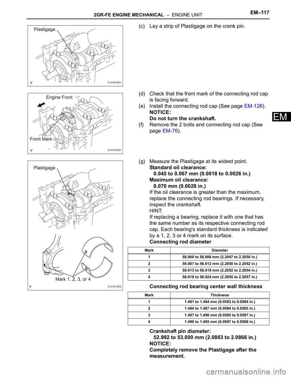
(c) Lay a strip of Plastigage on the crank pin.
(d) Check that the front mark of the connecting rod cap
is facing forward.
(e) Install the connecting rod cap (See page EM-126).
NOTICE:
Do not turn the crankshaft.
(f) Remove the 2 bolts and connecting rod cap (See
page EM-76).
(g) Measure the Plastigage at its widest point.
Standard oil clearance:
0.045 to 0.067 mm (0.0018 to 0.0026 in.)
Maximum oil clearance:
0.070 mm (0.0028 in.)
If the oil clearance is greater than the maximum,
replace the connecting rod bearings. If necessary,
inspect the crankshaft.
HINT:
If replacing a bearing, replace it with one that has
the same number as its respective connecting rod
cap. Each bearing's standard thickness is indicated
by a 1, 2, 3 or 4 mark on its surface.
Connecting rod diameter
Connecting rod bearing center wall thickness
Crankshaft pin diameter:
52.992 to 53.000 mm (2.0863 to 2.0866 in.)
NOTICE:
Completely remove the Plastigage after the
measurement.
A131814E01
A131815E01
A131817E02
Mark Diameter
1 56.000 to 56.006 mm (2.2047 to 2.2050 in.)
2 56.007 to 56.012 mm (2.2050 to 2.2052 in.)
3 56.013 to 56.018 mm (2.2052 to 2.2054 in.)
4 56.019 to 56.024 mm (2.2055 to 2.2057 in.)
Mark Thickness
1 1.481 to 1.484 mm (0.0583 to 0.0584 in.)
2 1.484 to 1.487 mm (0.0584 to 0.0585 in.)
3 1.487 to 1.490 mm (0.0585 to 0.0587 in.)
4 1.490 to 1.493 mm (0.0587 to 0.0588 in.)
Page 1065 of 3000
EM–1182GR-FE ENGINE MECHANICAL – ENGINE UNIT
EM
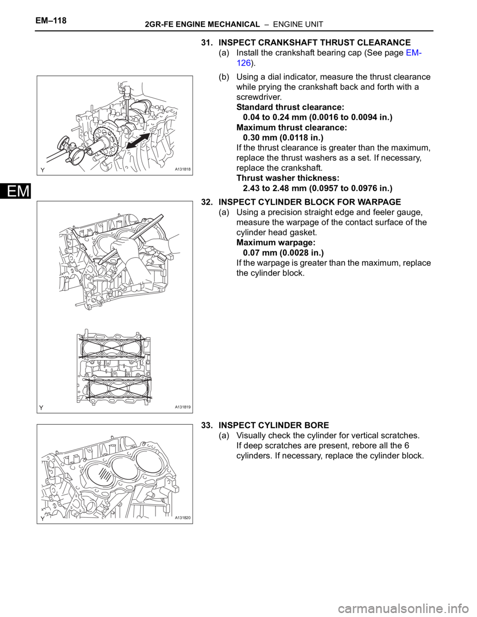
31. INSPECT CRANKSHAFT THRUST CLEARANCE
(a) Install the crankshaft bearing cap (See page EM-
126).
(b) Using a dial indicator, measure the thrust clearance
while prying the crankshaft back and forth with a
screwdriver.
Standard thrust clearance:
0.04 to 0.24 mm (0.0016 to 0.0094 in.)
Maximum thrust clearance:
0.30 mm (0.0118 in.)
If the thrust clearance is greater than the maximum,
replace the thrust washers as a set. If necessary,
replace the crankshaft.
Thrust washer thickness:
2.43 to 2.48 mm (0.0957 to 0.0976 in.)
32. INSPECT CYLINDER BLOCK FOR WARPAGE
(a) Using a precision straight edge and feeler gauge,
measure the warpage of the contact surface of the
cylinder head gasket.
Maximum warpage:
0.07 mm (0.0028 in.)
If the warpage is greater than the maximum, replace
the cylinder block.
33. INSPECT CYLINDER BORE
(a) Visually check the cylinder for vertical scratches.
If deep scratches are present, rebore all the 6
cylinders. If necessary, replace the cylinder block.
A131818
A131819
A131820
Page 1069 of 3000
EM–1222GR-FE ENGINE MECHANICAL – ENGINE UNIT
EM
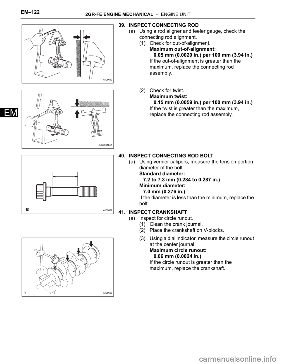
39. INSPECT CONNECTING ROD
(a) Using a rod aligner and feeler gauge, check the
connecting rod alignment.
(1) Check for out-of-alignment.
Maximum out-of-alignment:
0.05 mm (0.0020 in.) per 100 mm (3.94 in.)
If the out-of-alignment is greater than the
maximum, replace the connecting rod
assembly.
(2) Check for twist.
Maximum twist:
0.15 mm (0.0059 in.) per 100 mm (3.94 in.)
If the twist is greater than the maximum,
replace the connecting rod assembly.
40. INSPECT CONNECTING ROD BOLT
(a) Using vernier calipers, measure the tension portion
diameter of the bolt.
Standard diameter:
7.2 to 7.3 mm (0.284 to 0.287 in.)
Minimum diameter:
7.0 mm (0.276 in.)
If the diameter is less than the minimum, replace the
bolt.
41. INSPECT CRANKSHAFT
(a) Inspect for circle runout.
(1) Clean the crank journal.
(2) Place the crankshaft on V-blocks.
(3) Using a dial indicator, measure the circle runout
at the center journal.
Maximum circle runout:
0.06 mm (0.0024 in.)
If the circle runout is greater than the
maximum, replace the crankshaft.
A109690
A109691E01
A109692
A109693
Page 1070 of 3000
2GR-FE ENGINE MECHANICAL – ENGINE UNITEM–123
EM
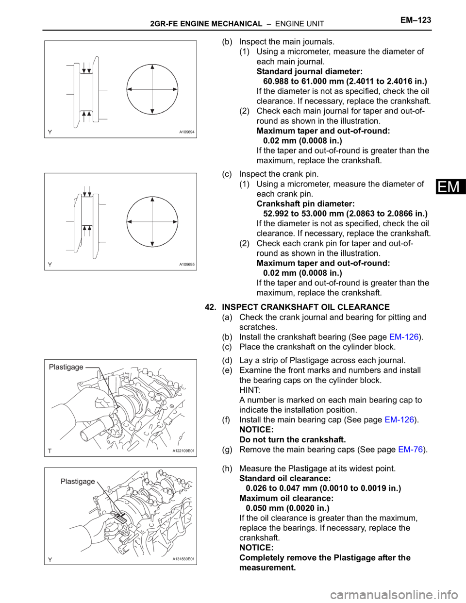
(b) Inspect the main journals.
(1) Using a micrometer, measure the diameter of
each main journal.
Standard journal diameter:
60.988 to 61.000 mm (2.4011 to 2.4016 in.)
If the diameter is not as specified, check the oil
clearance. If necessary, replace the crankshaft.
(2) Check each main journal for taper and out-of-
round as shown in the illustration.
Maximum taper and out-of-round:
0.02 mm (0.0008 in.)
If the taper and out-of-round is greater than the
maximum, replace the crankshaft.
(c) Inspect the crank pin.
(1) Using a micrometer, measure the diameter of
each crank pin.
Crankshaft pin diameter:
52.992 to 53.000 mm (2.0863 to 2.0866 in.)
If the diameter is not as specified, check the oil
clearance. If necessary, replace the crankshaft.
(2) Check each crank pin for taper and out-of-
round as shown in the illustration.
Maximum taper and out-of-round:
0.02 mm (0.0008 in.)
If the taper and out-of-round is greater than the
maximum, replace the crankshaft.
42. INSPECT CRANKSHAFT OIL CLEARANCE
(a) Check the crank journal and bearing for pitting and
scratches.
(b) Install the crankshaft bearing (See page EM-126).
(c) Place the crankshaft on the cylinder block.
(d) Lay a strip of Plastigage across each journal.
(e) Examine the front marks and numbers and install
the bearing caps on the cylinder block.
HINT:
A number is marked on each main bearing cap to
indicate the installation position.
(f) Install the main bearing cap (See page EM-126).
NOTICE:
Do not turn the crankshaft.
(g) Remove the main bearing caps (See page EM-76).
(h) Measure the Plastigage at its widest point.
Standard oil clearance:
0.026 to 0.047 mm (0.0010 to 0.0019 in.)
Maximum oil clearance:
0.050 mm (0.0020 in.)
If the oil clearance is greater than the maximum,
replace the bearings. If necessary, replace the
crankshaft.
NOTICE:
Completely remove the Plastigage after the
measurement.
A109694
A109695
A122109E01
A131830E01
Page 1075 of 3000
EM–1282GR-FE ENGINE MECHANICAL – ENGINE UNIT
EM
(b) Gradually heat the piston to approximately 80C
(176
F).
(c) Coat the piston pin with engine oil.
(d) Align the front marks of the piston and connecting
rod, and push in the piston pin with your thumb.
HINT:
The piston and pin are a matched set.
(e) Check the fitting condition between the piston and
piston pin by trying to move the piston back and
forth on the piston pin.
(f) Using a screwdriver, install a new piston pin hole
snap ring at the other end of the piston pin hole.
HINT:
Be sure that the end gap of the snap ring is not
aligned with the pin hole cutout portion of the piston.
5. INSTALL PISTON RING SET
(a) Install the oil ring expander and 2 side rails by hand.
A125895E02
A131878E01
A107551
A131879E02
Page 1079 of 3000
EM–1322GR-FE ENGINE MECHANICAL – ENGINE UNIT
EM
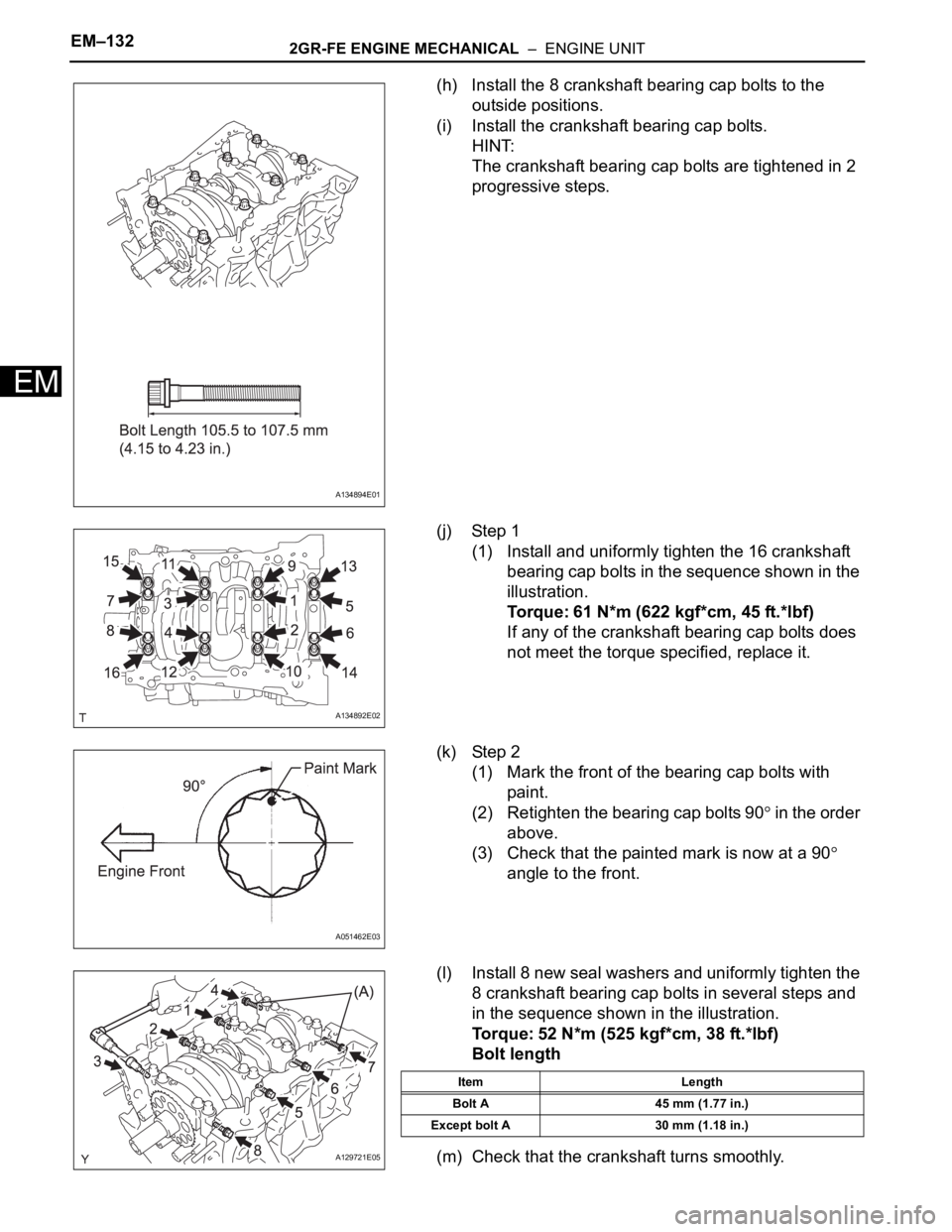
(h) Install the 8 crankshaft bearing cap bolts to the
outside positions.
(i) Install the crankshaft bearing cap bolts.
HINT:
The crankshaft bearing cap bolts are tightened in 2
progressive steps.
(j) Step 1
(1) Install and uniformly tighten the 16 crankshaft
bearing cap bolts in the sequence shown in the
illustration.
Torque: 61 N*m (622 kgf*cm, 45 ft.*lbf)
If any of the crankshaft bearing cap bolts does
not meet the torque specified, replace it.
(k) Step 2
(1) Mark the front of the bearing cap bolts with
paint.
(2) Retighten the bearing cap bolts 90
in the order
above.
(3) Check that the painted mark is now at a 90
angle to the front.
(l) Install 8 new seal washers and uniformly tighten the
8 crankshaft bearing cap bolts in several steps and
in the sequence shown in the illustration.
Torque: 52 N*m (525 kgf*cm, 38 ft.*lbf)
Bolt length
(m) Check that the crankshaft turns smoothly.
A134894E01
A134892E02
A051462E03
A129721E05
Item Length
Bolt A 45 mm (1.77 in.)
Except bolt A 30 mm (1.18 in.)
Page 1080 of 3000
2GR-FE ENGINE MECHANICAL – ENGINE UNITEM–133
EM
(n) Check the crankshaft thrust clearance (See page
EM-118).
9. INSTALL CONNECTING ROD BEARING
(a) Install the connecting rod bearing to the connecting
rod and connecting rod cap.
(b) Using vernier calipers, measure the distance
between the connecting rod's and bearing cap's
edges and the connecting rod bearing's edge.
Dimension (A - B):
0.7 mm (0.0276 in.) or less
NOTICE:
Do not apply engine oil to the bearings and the
contact surfaces.
10. INSTALL PISTON SUB-ASSEMBLY WITH
CONNECTING ROD
(a) Apply engine oil to the cylinder walls, the pistons,
and the surfaces of the connecting rod bearings.
(b) Position the piston rings so that the ring ends are as
shown in the illustration.
NOTICE:
Do not align the ring ends.
A094752E02
A131881E01
Page 1081 of 3000
EM–1342GR-FE ENGINE MECHANICAL – ENGINE UNIT
EM
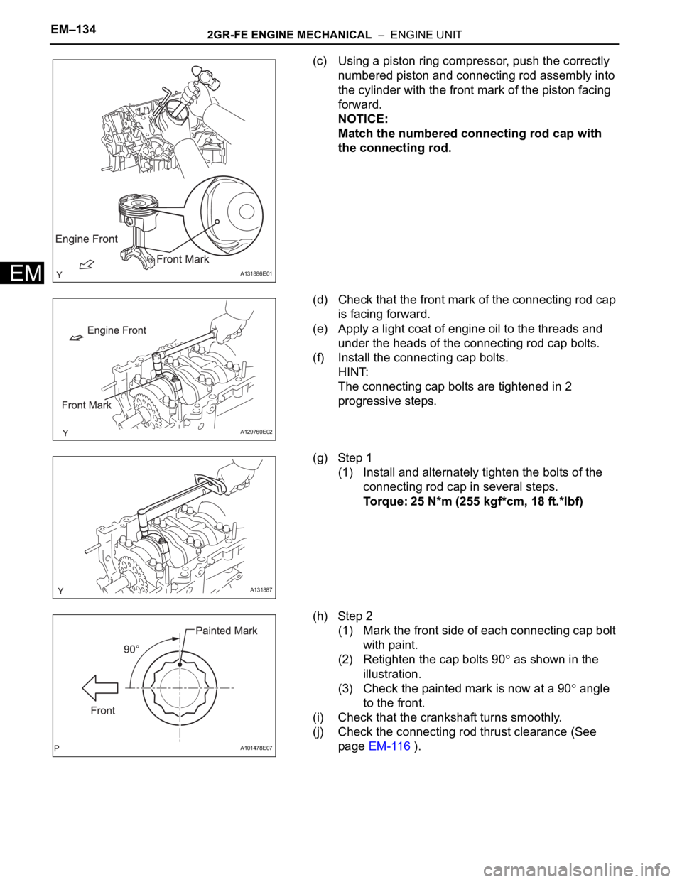
(c) Using a piston ring compressor, push the correctly
numbered piston and connecting rod assembly into
the cylinder with the front mark of the piston facing
forward.
NOTICE:
Match the numbered connecting rod cap with
the connecting rod.
(d) Check that the front mark of the connecting rod cap
is facing forward.
(e) Apply a light coat of engine oil to the threads and
under the heads of the connecting rod cap bolts.
(f) Install the connecting cap bolts.
HINT:
The connecting cap bolts are tightened in 2
progressive steps.
(g) Step 1
(1) Install and alternately tighten the bolts of the
connecting rod cap in several steps.
Torque: 25 N*m (255 kgf*cm, 18 ft.*lbf)
(h) Step 2
(1) Mark the front side of each connecting cap bolt
with paint.
(2) Retighten the cap bolts 90
as shown in the
illustration.
(3) Check the painted mark is now at a 90
angle
to the front.
(i) Check that the crankshaft turns smoothly.
(j) Check the connecting rod thrust clearance (See
page EM-116 ).
A131886E01
A129760E02
A131887
A101478E07