Page 962 of 3000
2GR-FE ENGINE MECHANICAL – ENGINE UNITEM–153
EM
(d) Remove the hexagon wrench of the chain tensioner.
Check that each timing mark is aligned with the
crankshaft at the TDC / compression.
(e) Remove the pulley set bolt.
45. INSTALL TIMING CHAIN CASE OIL SEAL
(a) Using SST, tap in a new oil seal until its surface is
flush with the timing gear case edge.
SST 09223-22010, 09506-35010
NOTICE:
• Keep the lip free of foreign matter.
• Do not tap on the oil seal at an angle.
• Make sure that the oil seal edge does not
stick out of the timing chain case.
A134895E05
A125109E04
Page 972 of 3000
2GR-FE ENGINE MECHANICAL – ENGINE UNITEM–163
EM
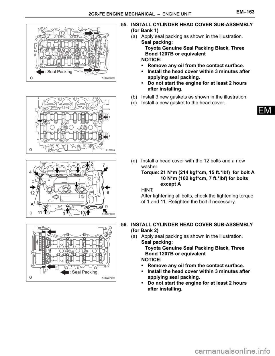
55. INSTALL CYLINDER HEAD COVER SUB-ASSEMBLY
(for Bank 1)
(a) Apply seal packing as shown in the illustration.
Seal packing:
Toyota Genuine Seal Packing Black, Three
Bond 1207B or equivalent
NOTICE:
• Remove any oil from the contact surface.
• Install the head cover within 3 minutes after
applying seal packing.
• Do not start the engine for at least 2 hours
after installing.
(b) Install 3 new gaskets as shown in the illustration.
(c) Install a new gasket to the head cover.
(d) Install a head cover with the 12 bolts and a new
washer.
Torque: 21 N*m (214 kgf*cm, 15 ft.*lbf) for bolt A
10 N*m (102 kgf*cm, 7 ft.*lbf) for bolts
except A
HINT:
After tightening all bolts, check the tightening torque
of 1 and 11. Retighten the bolt if necessary.
56. INSTALL CYLINDER HEAD COVER SUB-ASSEMBLY
(for Bank 2)
(a) Apply seal packing as shown in the illustration.
Seal packing:
Toyota Genuine Seal Packing Black, Three
Bond 1207B or equivalent
NOTICE:
• Remove any oil from the contact surface.
• Install the head cover within 3 minutes after
applying seal packing.
• Do not start the engine for at least 2 hours
after installing.
A132236E01
A129699
A129679E01
A132237E01
Page 973 of 3000
EM–1642GR-FE ENGINE MECHANICAL – ENGINE UNIT
EM
(b) Install 3 new gaskets as shown in the illustration.
(c) Install a new cylinder head cover gasket to the
cylinder head cover sub-assembly.
(d) Install the cylinder head cover with the 12 bolts and
a new washer.
Torque: 21 N*m (214 kgf*cm, 15 ft.*lbf) for bolt A
10 N*m (102 kgf*cm, 7 ft.*lbf) for bolts
except A
HINT:
After tightening all bolts, check the tightening torque
of 1 and 10. Retighten the bolt if necessary.
57. INSTALL WATER OUTLET
(a) Install 2 new gaskets and a new O-ring.
HINT:
Apply soapy water to the O-ring.
(b) Install the water outlet with the 2 bolts and 4 nuts.
Torque: 10 N*m (102 kgf*cm, 7 ft.*lbf) for bolts
10 N*m (103 kgf*cm, 7 ft.*lbf) for nuts
NOTICE:
Be careful that the O-ring does not get caught
between the parts.
A129705
A129678E03
A129677
A129676E01
Page 976 of 3000
2GR-FE ENGINE MECHANICAL – ENGINE UNITEM–167
EM
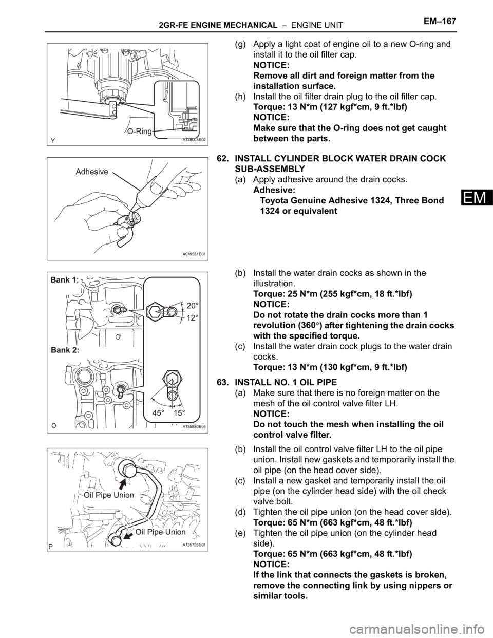
(g) Apply a light coat of engine oil to a new O-ring and
install it to the oil filter cap.
NOTICE:
Remove all dirt and foreign matter from the
installation surface.
(h) Install the oil filter drain plug to the oil filter cap.
Torque: 13 N*m (127 kgf*cm, 9 ft.*lbf)
NOTICE:
Make sure that the O-ring does not get caught
between the parts.
62. INSTALL CYLINDER BLOCK WATER DRAIN COCK
SUB-ASSEMBLY
(a) Apply adhesive around the drain cocks.
Adhesive:
Toyota Genuine Adhesive 1324, Three Bond
1324 or equivalent
(b) Install the water drain cocks as shown in the
illustration.
Torque: 25 N*m (255 kgf*cm, 18 ft.*lbf)
NOTICE:
Do not rotate the drain cocks more than 1
revolution (360
) after tightening the drain cocks
with the specified torque.
(c) Install the water drain cock plugs to the water drain
cocks.
Torque: 13 N*m (130 kgf*cm, 9 ft.*lbf)
63. INSTALL NO. 1 OIL PIPE
(a) Make sure that there is no foreign matter on the
mesh of the oil control valve filter LH.
NOTICE:
Do not touch the mesh when installing the oil
control valve filter.
(b) Install the oil control valve filter LH to the oil pipe
union. Install new gaskets and temporarily install the
oil pipe (on the head cover side).
(c) Install a new gasket and temporarily install the oil
pipe (on the cylinder head side) with the oil check
valve bolt.
(d) Tighten the oil pipe union (on the head cover side).
Torque: 65 N*m (663 kgf*cm, 48 ft.*lbf)
(e) Tighten the oil pipe union (on the cylinder head
side).
Torque: 65 N*m (663 kgf*cm, 48 ft.*lbf)
NOTICE:
If the link that connects the gaskets is broken,
remove the connecting link by using nippers or
similar tools.
A128003E02
A076531E01
A135830E03
A135726E01
Page 977 of 3000
EM–1682GR-FE ENGINE MECHANICAL – ENGINE UNIT
EM
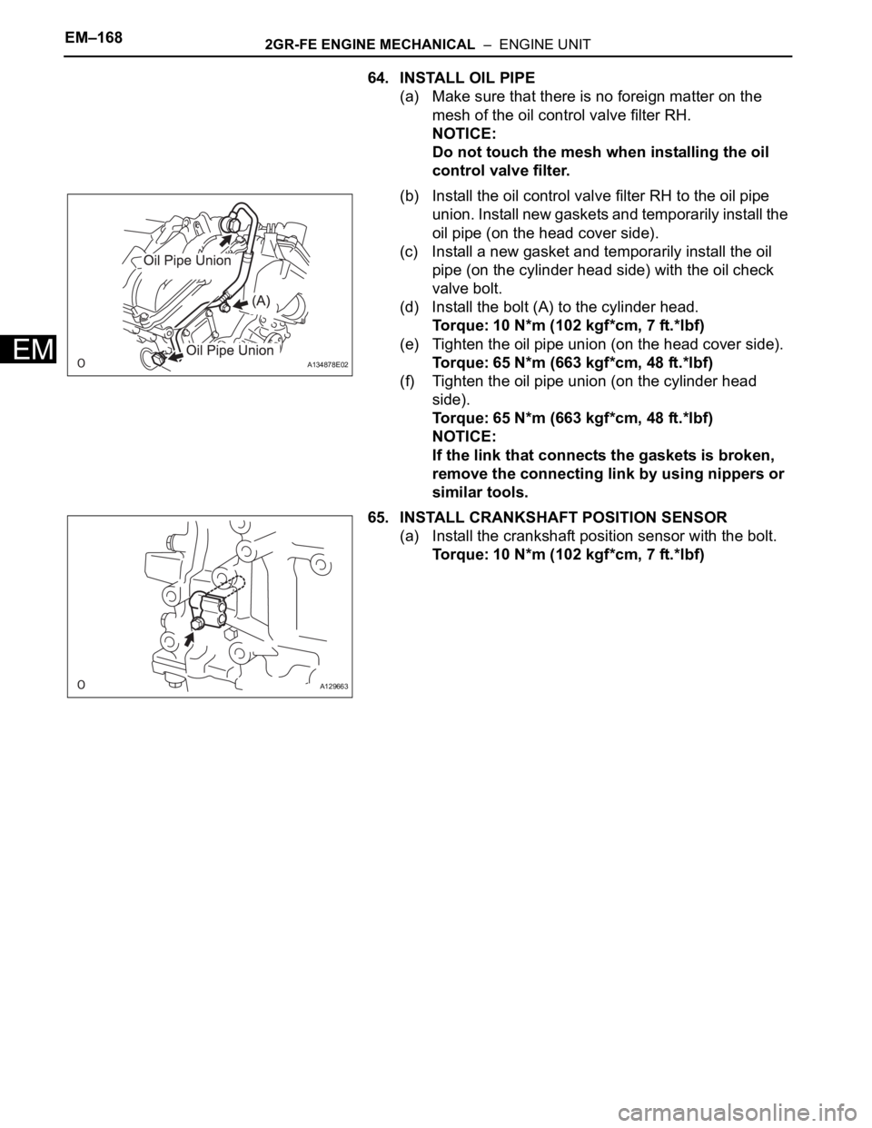
64. INSTALL OIL PIPE
(a) Make sure that there is no foreign matter on the
mesh of the oil control valve filter RH.
NOTICE:
Do not touch the mesh when installing the oil
control valve filter.
(b) Install the oil control valve filter RH to the oil pipe
union. Install new gaskets and temporarily install the
oil pipe (on the head cover side).
(c) Install a new gasket and temporarily install the oil
pipe (on the cylinder head side) with the oil check
valve bolt.
(d) Install the bolt (A) to the cylinder head.
Torque: 10 N*m (102 kgf*cm, 7 ft.*lbf)
(e) Tighten the oil pipe union (on the head cover side).
Torque: 65 N*m (663 kgf*cm, 48 ft.*lbf)
(f) Tighten the oil pipe union (on the cylinder head
side).
Torque: 65 N*m (663 kgf*cm, 48 ft.*lbf)
NOTICE:
If the link that connects the gaskets is broken,
remove the connecting link by using nippers or
similar tools.
65. INSTALL CRANKSHAFT POSITION SENSOR
(a) Install the crankshaft position sensor with the bolt.
Torque: 10 N*m (102 kgf*cm, 7 ft.*lbf)
A134878E02
A129663
Page 980 of 3000
EM–62GR-FE ENGINE MECHANICAL – DRIVE BELT
EM
REMOVAL
1. REMOVE FRONT WHEEL RH
2. REMOVE FRONT FENDER APRON SEAL RH (See
page EM-26)
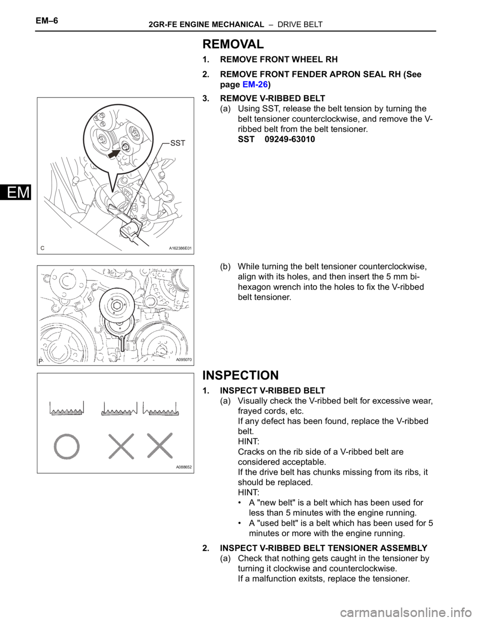
3. REMOVE V-RIBBED BELT
(a) Using SST, release the belt tension by turning the
belt tensioner counterclockwise, and remove the V-
ribbed belt from the belt tensioner.
SST 09249-63010
(b) While turning the belt tensioner counterclockwise,
align with its holes, and then insert the 5 mm bi-
hexagon wrench into the holes to fix the V-ribbed
belt tensioner.
INSPECTION
1. INSPECT V-RIBBED BELT
(a) Visually check the V-ribbed belt for excessive wear,
frayed cords, etc.
If any defect has been found, replace the V-ribbed
belt.
HINT:
Cracks on the rib side of a V-ribbed belt are
considered acceptable.
If the drive belt has chunks missing from its ribs, it
should be replaced.
HINT:
• A "new belt" is a belt which has been used for
less than 5 minutes with the engine running.
• A "used belt" is a belt which has been used for 5
minutes or more with the engine running.
2. INSPECT V-RIBBED BELT TENSIONER ASSEMBLY
(a) Check that nothing gets caught in the tensioner by
turning it clockwise and counterclockwise.
If a malfunction exitsts, replace the tensioner.
A162386E01
A095070
A088652
Page 981 of 3000
2GR-FE ENGINE MECHANICAL – DRIVE BELTEM–7
EM
INSTALLATION
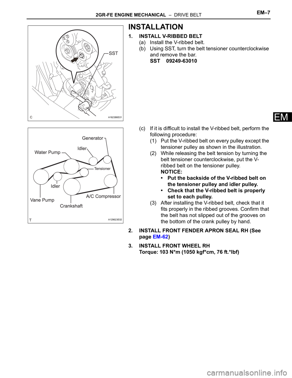
1. INSTALL V-RIBBED BELT
(a) Install the V-ribbed belt.
(b) Using SST, turn the belt tensioner counterclockwise
and remove the bar.
SST 09249-63010
(c) If it is difficult to install the V-ribbed belt, perform the
following procedure:
(1) Put the V-ribbed belt on every pulley except the
tensioner pulley as shown in the illustration.
(2) While releasing the belt tension by turning the
belt tensioner counterclockwise, put the V-
ribbed belt on the tensioner pulley.
NOTICE:
• Put the backside of the V-ribbed belt on
the tensioner pulley and idler pulley.
• Check that the V-ribbed belt is properly
set to each pulley.
(3) After installing the V-ribbed belt, check that it
fits properly in the ribbed grooves. Confirm that
the belt has not slipped out of the grooves on
the bottom of the crank pulley by hand.
2. INSTALL FRONT FENDER APRON SEAL RH (See
page EM-62)
3. INSTALL FRONT WHEEL RH
Torque: 103 N*m (1050 kgf*cm, 76 ft.*lbf)
A162386E01
A129623E02
Page 990 of 3000
2GR-FE ENGINE MECHANICAL – ENGINE ASSEMBLYEM–31
EM
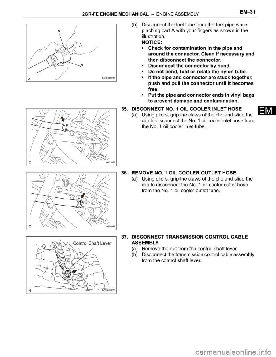
(b) Disconnect the fuel tube from the fuel pipe while
pinching part A with your fingers as shown in the
illustration.
NOTICE:
• Check for contamination in the pipe and
around the connector. Clean if necessary and
then disconnect the connector.
• Disconnect the connector by hand.
• Do not bend, fold or rotate the nylon tube.
• If the pipe and connector are stuck together,
push and pull the connector until it becomes
free.
• Put the pipe and connector ends in vinyl bags
to prevent damage and contamination.
35. DISCONNECT NO. 1 OIL COOLER INLET HOSE
(a) Using pliers, grip the claws of the clip and slide the
clip to disconnect the No. 1 oil cooler inlet hose from
the No. 1 oil cooler inlet tube.
36. REMOVE NO. 1 OIL COOLER OUTLET HOSE
(a) Using pliers, grip the claws of the clip and slide the
clip to disconnect the No. 1 oil cooler outlet hose
from the No. 1 oil cooler outlet tube.
37. DISCONNECT TRANSMISSION CONTROL CABLE
ASSEMBLY
(a) Remove the nut from the control shaft lever.
(b) Disconnect the transmission control cable assembly
from the control shaft lever.
B012941E15
A155032
A155031
D025414E03