Page 934 of 3000

EM–42GR-FE ENGINE MECHANICAL – ENGINE
EM
(h) Install the 6 ignition coils.
Torque: 10 N*m (102 kgf*cm, 7 ft.*lbf)
(i) Install the intake air surge tank (See page ES-522).
10. INSPECT CO/HC
(a) Start the engine.
(b) Run the engine at 2500 rpm for approximately 180
seconds.
(c) Insert the CO/HC meter testing probe at least 40 cm
(1.3 ft.) into the tailpipe during idling.
(d) Check CO/HC concentration at idle and/or 2500
rpm.
HINT:
Check regulations and restrictions in your area
when performing 2 mode CO/HC concentration
testing (engine check at both idle speed and at 2500
rpm).
If the CO/HC concentration does not comply with
regulations, perform troubleshooting in the order
given below.
(1) Check air fuel ratio sensor and heated oxygen
sensor operation.
(2) See the table below for possible causes, and
then inspect and repair.
CO HC Problems Causes
Normal High Rough idle1. Faulty ignitions:
– Incorrect timing
– Fouled, shorted or improperly gapped plugs
2. Incorrect valve clearance
3. Leaks in intake and exhaust valves
4. Leaks in cylinders
Low HighRough idle
(fluctuating HC reading)1. Vacuum leaks:
– PCV hoses
– Intake manifold
– Throttle body
– Brake booster line
2. Lean mixture causing misfire
High HighRough idle
(black smoke from exhaust)1. Restricted air filter
2. Plugged PCV valve
3. Faulty SFI system:
– Faulty fuel pressure regulator
– Defective ECT sensor
– Defective MAF meter
–Faulty ECM
– Faulty injectors
– Faulty throttle position sensor
Page 937 of 3000
EM–1282GR-FE ENGINE MECHANICAL – ENGINE UNIT
EM
(b) Gradually heat the piston to approximately 80C
(176
F).
(c) Coat the piston pin with engine oil.
(d) Align the front marks of the piston and connecting
rod, and push in the piston pin with your thumb.
HINT:
The piston and pin are a matched set.
(e) Check the fitting condition between the piston and
piston pin by trying to move the piston back and
forth on the piston pin.
(f) Using a screwdriver, install a new piston pin hole
snap ring at the other end of the piston pin hole.
HINT:
Be sure that the end gap of the snap ring is not
aligned with the pin hole cutout portion of the piston.
5. INSTALL PISTON RING SET
(a) Install the oil ring expander and 2 side rails by hand.
A125895E02
A131878E01
A107551
A131879E02
Page 941 of 3000
EM–1322GR-FE ENGINE MECHANICAL – ENGINE UNIT
EM
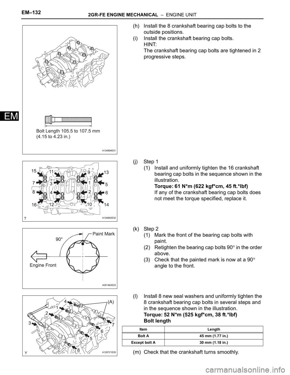
(h) Install the 8 crankshaft bearing cap bolts to the
outside positions.
(i) Install the crankshaft bearing cap bolts.
HINT:
The crankshaft bearing cap bolts are tightened in 2
progressive steps.
(j) Step 1
(1) Install and uniformly tighten the 16 crankshaft
bearing cap bolts in the sequence shown in the
illustration.
Torque: 61 N*m (622 kgf*cm, 45 ft.*lbf)
If any of the crankshaft bearing cap bolts does
not meet the torque specified, replace it.
(k) Step 2
(1) Mark the front of the bearing cap bolts with
paint.
(2) Retighten the bearing cap bolts 90
in the order
above.
(3) Check that the painted mark is now at a 90
angle to the front.
(l) Install 8 new seal washers and uniformly tighten the
8 crankshaft bearing cap bolts in several steps and
in the sequence shown in the illustration.
Torque: 52 N*m (525 kgf*cm, 38 ft.*lbf)
Bolt length
(m) Check that the crankshaft turns smoothly.
A134894E01
A134892E02
A051462E03
A129721E05
Item Length
Bolt A 45 mm (1.77 in.)
Except bolt A 30 mm (1.18 in.)
Page 942 of 3000
2GR-FE ENGINE MECHANICAL – ENGINE UNITEM–133
EM
(n) Check the crankshaft thrust clearance (See page
EM-118).
9. INSTALL CONNECTING ROD BEARING
(a) Install the connecting rod bearing to the connecting
rod and connecting rod cap.
(b) Using vernier calipers, measure the distance
between the connecting rod's and bearing cap's
edges and the connecting rod bearing's edge.
Dimension (A - B):
0.7 mm (0.0276 in.) or less
NOTICE:
Do not apply engine oil to the bearings and the
contact surfaces.
10. INSTALL PISTON SUB-ASSEMBLY WITH
CONNECTING ROD
(a) Apply engine oil to the cylinder walls, the pistons,
and the surfaces of the connecting rod bearings.
(b) Position the piston rings so that the ring ends are as
shown in the illustration.
NOTICE:
Do not align the ring ends.
A094752E02
A131881E01
Page 943 of 3000
EM–1342GR-FE ENGINE MECHANICAL – ENGINE UNIT
EM
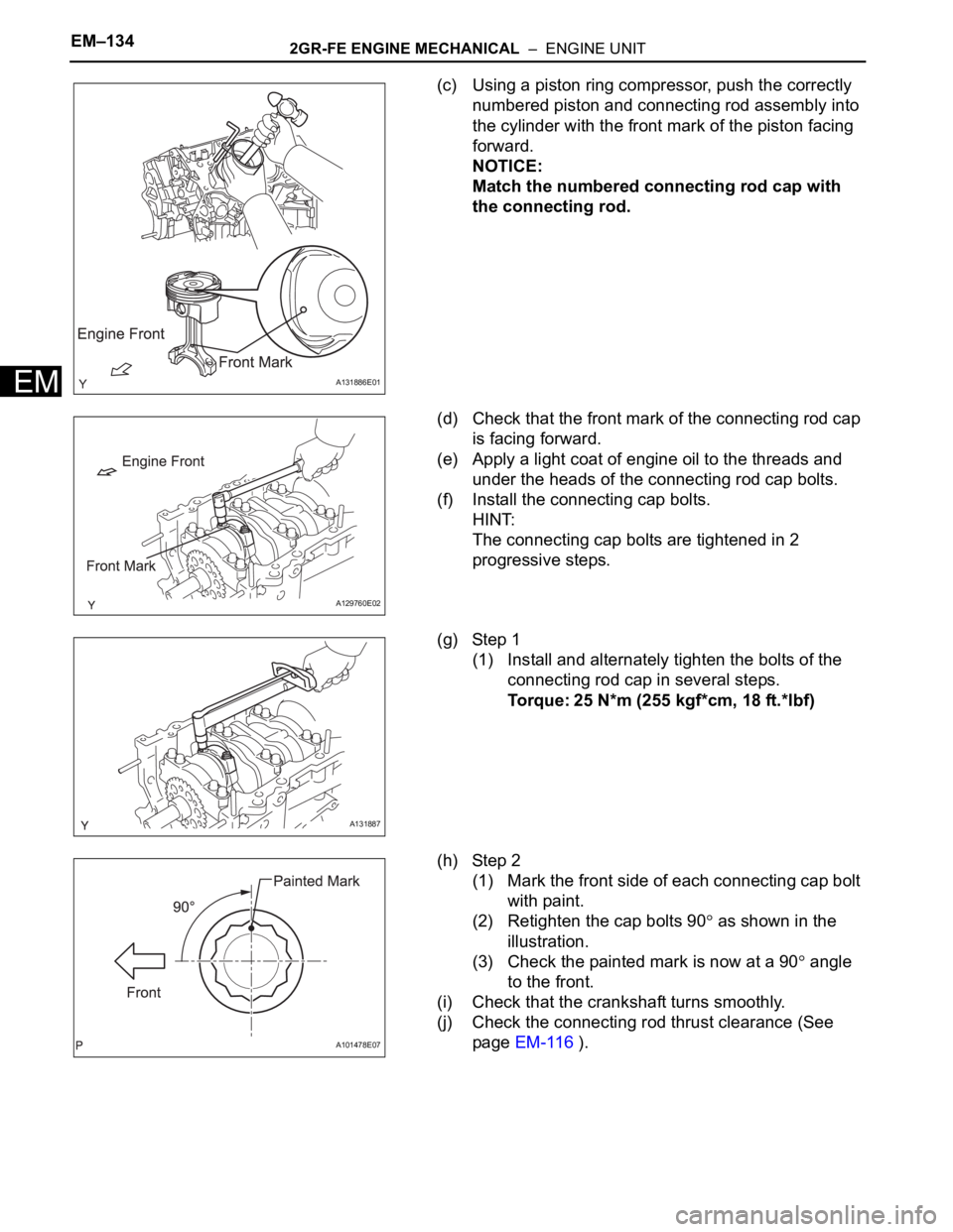
(c) Using a piston ring compressor, push the correctly
numbered piston and connecting rod assembly into
the cylinder with the front mark of the piston facing
forward.
NOTICE:
Match the numbered connecting rod cap with
the connecting rod.
(d) Check that the front mark of the connecting rod cap
is facing forward.
(e) Apply a light coat of engine oil to the threads and
under the heads of the connecting rod cap bolts.
(f) Install the connecting cap bolts.
HINT:
The connecting cap bolts are tightened in 2
progressive steps.
(g) Step 1
(1) Install and alternately tighten the bolts of the
connecting rod cap in several steps.
Torque: 25 N*m (255 kgf*cm, 18 ft.*lbf)
(h) Step 2
(1) Mark the front side of each connecting cap bolt
with paint.
(2) Retighten the cap bolts 90
as shown in the
illustration.
(3) Check the painted mark is now at a 90
angle
to the front.
(i) Check that the crankshaft turns smoothly.
(j) Check the connecting rod thrust clearance (See
page EM-116 ).
A131886E01
A129760E02
A131887
A101478E07
Page 952 of 3000
2GR-FE ENGINE MECHANICAL – ENGINE UNITEM–143
EM
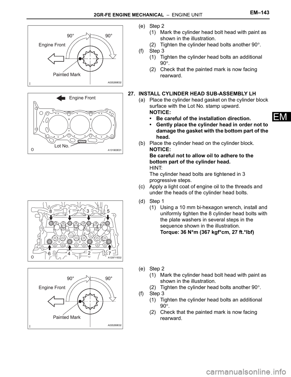
(e) Step 2
(1) Mark the cylinder head bolt head with paint as
shown in the illustration.
(2) Tighten the cylinder head bolts another 90
.
(f) Step 3
(1) Tighten the cylinder head bolts an additional
90
.
(2) Check that the painted mark is now facing
rearward.
27. INSTALL CYLINDER HEAD SUB-ASSEMBLY LH
(a) Place the cylinder head gasket on the cylinder block
surface with the Lot No. stamp upward.
NOTICE:
• Be careful of the installation direction.
• Gently place the cylinder head in order not to
damage the gasket with the bottom part of the
head.
(b) Place the cylinder head on the cylinder block.
NOTICE:
Be careful not to allow oil to adhere to the
bottom part of the cylinder head.
HINT:
The cylinder head bolts are tightened in 3
progressive steps.
(c) Apply a light coat of engine oil to the threads and
under the heads of the cylinder head bolts.
(d) Step 1
(1) Using a 10 mm bi-hexagon wrench, install and
uniformly tighten the 8 cylinder head bolts with
the plate washers in several steps in the
sequence shown in the illustration.
Torque: 36 N*m (367 kgf*cm, 27 ft.*lbf)
(e) Step 2
(1) Mark the cylinder head bolt head with paint as
shown in the illustration.
(2) Tighten the cylinder head bolts another 90
.
(f) Step 3
(1) Tighten the cylinder head bolts an additional
90
.
(2) Check that the painted mark is now facing
rearward.
A035289E02
A131900E01
A129711E02
A035289E02
Page 953 of 3000
EM–1442GR-FE ENGINE MECHANICAL – ENGINE UNIT
EM
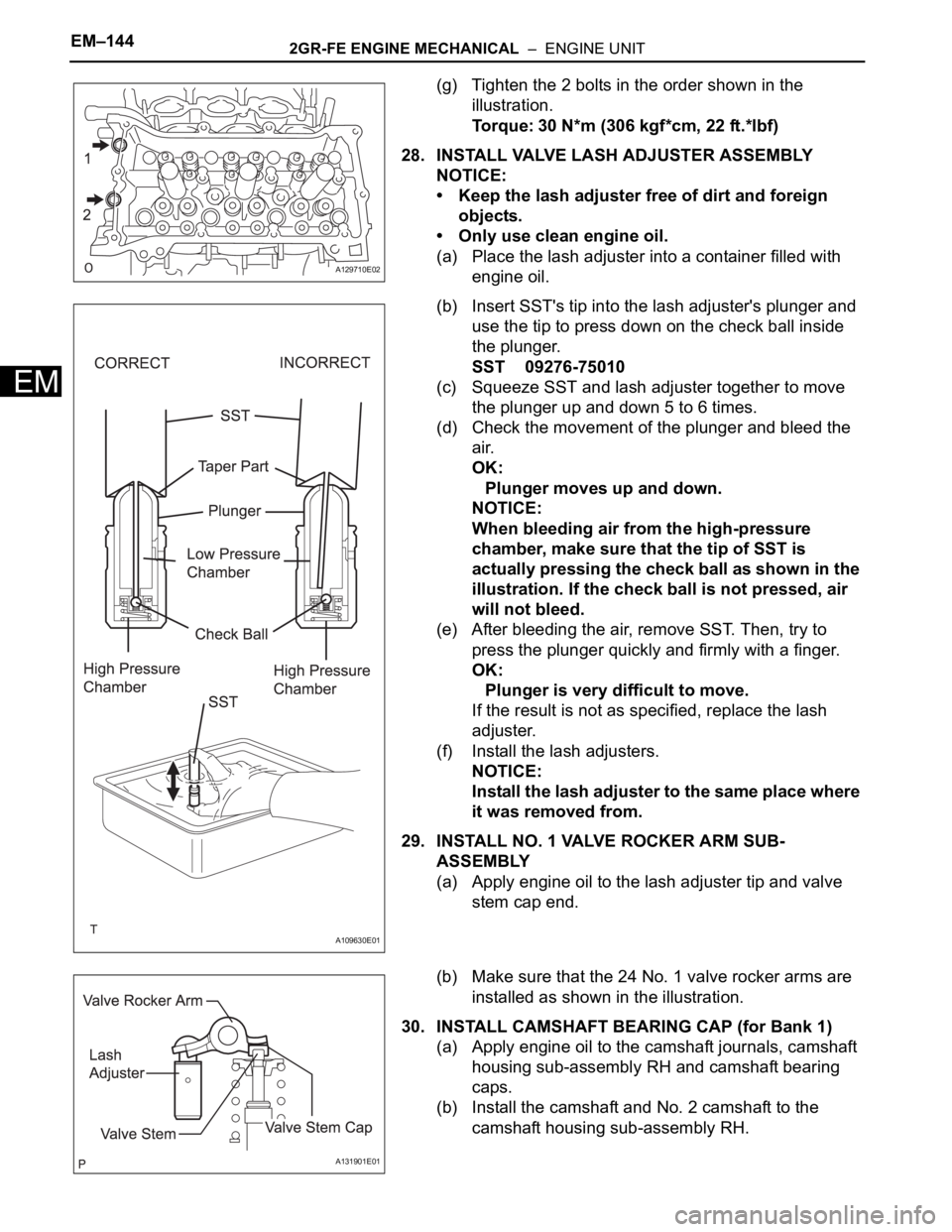
(g) Tighten the 2 bolts in the order shown in the
illustration.
Torque: 30 N*m (306 kgf*cm, 22 ft.*lbf)
28. INSTALL VALVE LASH ADJUSTER ASSEMBLY
NOTICE:
• Keep the lash adjuster free of dirt and foreign
objects.
• Only use clean engine oil.
(a) Place the lash adjuster into a container filled with
engine oil.
(b) Insert SST's tip into the lash adjuster's plunger and
use the tip to press down on the check ball inside
the plunger.
SST 09276-75010
(c) Squeeze SST and lash adjuster together to move
the plunger up and down 5 to 6 times.
(d) Check the movement of the plunger and bleed the
air.
OK:
Plunger moves up and down.
NOTICE:
When bleeding air from the high-pressure
chamber, make sure that the tip of SST is
actually pressing the check ball as shown in the
illustration. If the check ball is not pressed, air
will not bleed.
(e) After bleeding the air, remove SST. Then, try to
press the plunger quickly and firmly with a finger.
OK:
Plunger is very difficult to move.
If the result is not as specified, replace the lash
adjuster.
(f) Install the lash adjusters.
NOTICE:
Install the lash adjuster to the same place where
it was removed from.
29. INSTALL NO. 1 VALVE ROCKER ARM SUB-
ASSEMBLY
(a) Apply engine oil to the lash adjuster tip and valve
stem cap end.
(b) Make sure that the 24 No. 1 valve rocker arms are
installed as shown in the illustration.
30. INSTALL CAMSHAFT BEARING CAP (for Bank 1)
(a) Apply engine oil to the camshaft journals, camshaft
housing sub-assembly RH and camshaft bearing
caps.
(b) Install the camshaft and No. 2 camshaft to the
camshaft housing sub-assembly RH.
A129710E02
A109630E01
A131901E01
Page 959 of 3000
EM–1502GR-FE ENGINE MECHANICAL – ENGINE UNIT
EM
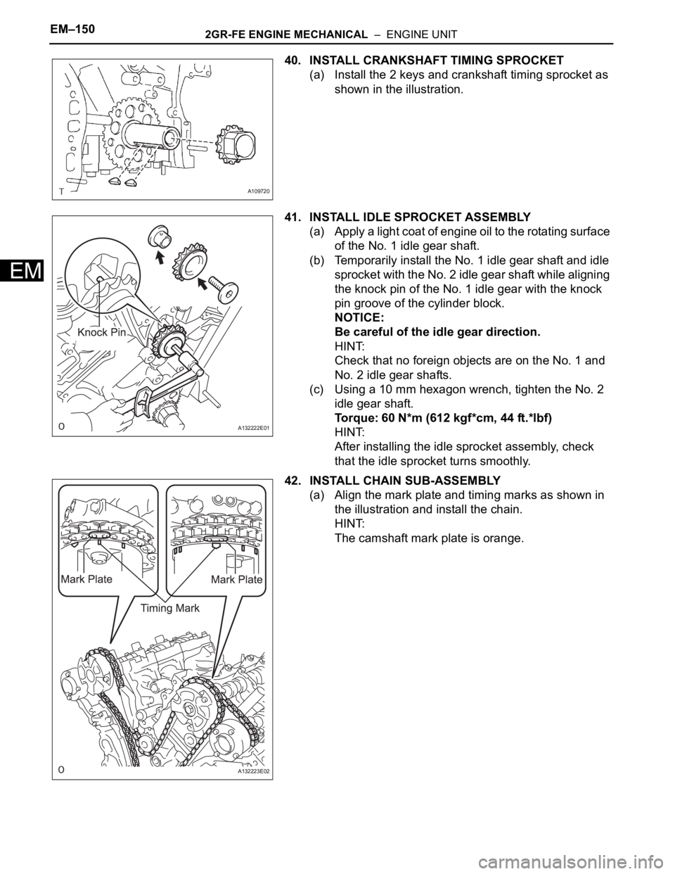
40. INSTALL CRANKSHAFT TIMING SPROCKET
(a) Install the 2 keys and crankshaft timing sprocket as
shown in the illustration.
41. INSTALL IDLE SPROCKET ASSEMBLY
(a) Apply a light coat of engine oil to the rotating surface
of the No. 1 idle gear shaft.
(b) Temporarily install the No. 1 idle gear shaft and idle
sprocket with the No. 2 idle gear shaft while aligning
the knock pin of the No. 1 idle gear with the knock
pin groove of the cylinder block.
NOTICE:
Be careful of the idle gear direction.
HINT:
Check that no foreign objects are on the No. 1 and
No. 2 idle gear shafts.
(c) Using a 10 mm hexagon wrench, tighten the No. 2
idle gear shaft.
Torque: 60 N*m (612 kgf*cm, 44 ft.*lbf)
HINT:
After installing the idle sprocket assembly, check
that the idle sprocket turns smoothly.
42. INSTALL CHAIN SUB-ASSEMBLY
(a) Align the mark plate and timing marks as shown in
the illustration and install the chain.
HINT:
The camshaft mark plate is orange.
A109720
A132222E01
A132223E02