2007 TOYOTA SIENNA check engine
[x] Cancel search: check enginePage 921 of 3000
EM–1162GR-FE ENGINE MECHANICAL – ENGINE UNIT
EM
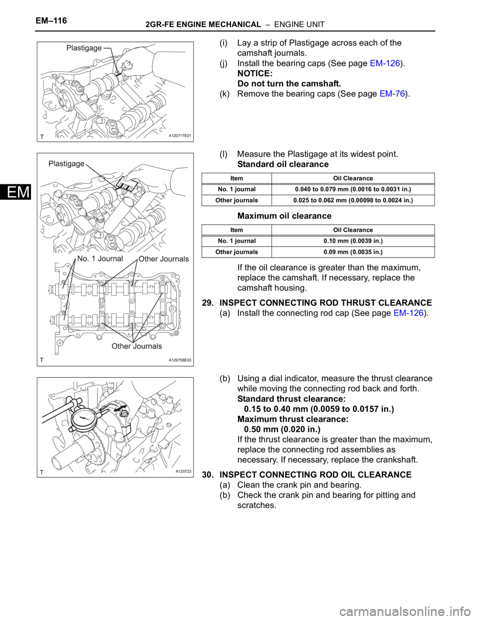
(i) Lay a strip of Plastigage across each of the
camshaft journals.
(j) Install the bearing caps (See page EM-126).
NOTICE:
Do not turn the camshaft.
(k) Remove the bearing caps (See page EM-76).
(l) Measure the Plastigage at its widest point.
Standard oil clearance
Maximum oil clearance
If the oil clearance is greater than the maximum,
replace the camshaft. If necessary, replace the
camshaft housing.
29. INSPECT CONNECTING ROD THRUST CLEARANCE
(a) Install the connecting rod cap (See page EM-126).
(b) Using a dial indicator, measure the thrust clearance
while moving the connecting rod back and forth.
Standard thrust clearance:
0.15 to 0.40 mm (0.0059 to 0.0157 in.)
Maximum thrust clearance:
0.50 mm (0.020 in.)
If the thrust clearance is greater than the maximum,
replace the connecting rod assemblies as
necessary. If necessary, replace the crankshaft.
30. INSPECT CONNECTING ROD OIL CLEARANCE
(a) Clean the crank pin and bearing.
(b) Check the crank pin and bearing for pitting and
scratches.
A120717E01
A129758E03
Item Oil Clearance
No. 1 journal 0.040 to 0.079 mm (0.0016 to 0.0031 in.)
Other journals 0.025 to 0.062 mm (0.00098 to 0.0024 in.)
Item Oil Clearance
No. 1 journal 0.10 mm (0.0039 in.)
Other journals 0.09 mm (0.0035 in.)
A120723
Page 922 of 3000
2GR-FE ENGINE MECHANICAL – ENGINE UNITEM–117
EM
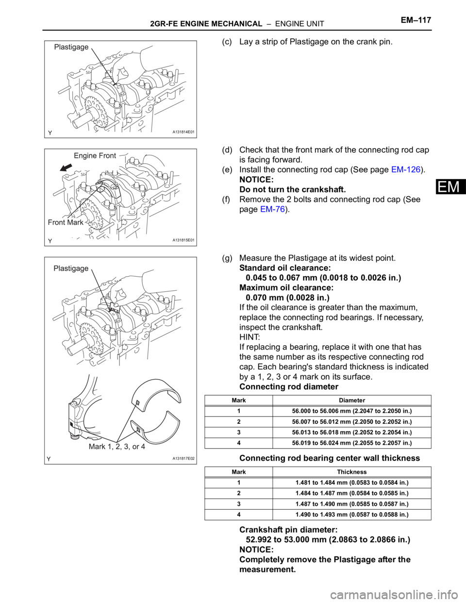
(c) Lay a strip of Plastigage on the crank pin.
(d) Check that the front mark of the connecting rod cap
is facing forward.
(e) Install the connecting rod cap (See page EM-126).
NOTICE:
Do not turn the crankshaft.
(f) Remove the 2 bolts and connecting rod cap (See
page EM-76).
(g) Measure the Plastigage at its widest point.
Standard oil clearance:
0.045 to 0.067 mm (0.0018 to 0.0026 in.)
Maximum oil clearance:
0.070 mm (0.0028 in.)
If the oil clearance is greater than the maximum,
replace the connecting rod bearings. If necessary,
inspect the crankshaft.
HINT:
If replacing a bearing, replace it with one that has
the same number as its respective connecting rod
cap. Each bearing's standard thickness is indicated
by a 1, 2, 3 or 4 mark on its surface.
Connecting rod diameter
Connecting rod bearing center wall thickness
Crankshaft pin diameter:
52.992 to 53.000 mm (2.0863 to 2.0866 in.)
NOTICE:
Completely remove the Plastigage after the
measurement.
A131814E01
A131815E01
A131817E02
Mark Diameter
1 56.000 to 56.006 mm (2.2047 to 2.2050 in.)
2 56.007 to 56.012 mm (2.2050 to 2.2052 in.)
3 56.013 to 56.018 mm (2.2052 to 2.2054 in.)
4 56.019 to 56.024 mm (2.2055 to 2.2057 in.)
Mark Thickness
1 1.481 to 1.484 mm (0.0583 to 0.0584 in.)
2 1.484 to 1.487 mm (0.0584 to 0.0585 in.)
3 1.487 to 1.490 mm (0.0585 to 0.0587 in.)
4 1.490 to 1.493 mm (0.0587 to 0.0588 in.)
Page 923 of 3000
EM–1182GR-FE ENGINE MECHANICAL – ENGINE UNIT
EM
31. INSPECT CRANKSHAFT THRUST CLEARANCE
(a) Install the crankshaft bearing cap (See page EM-
126).
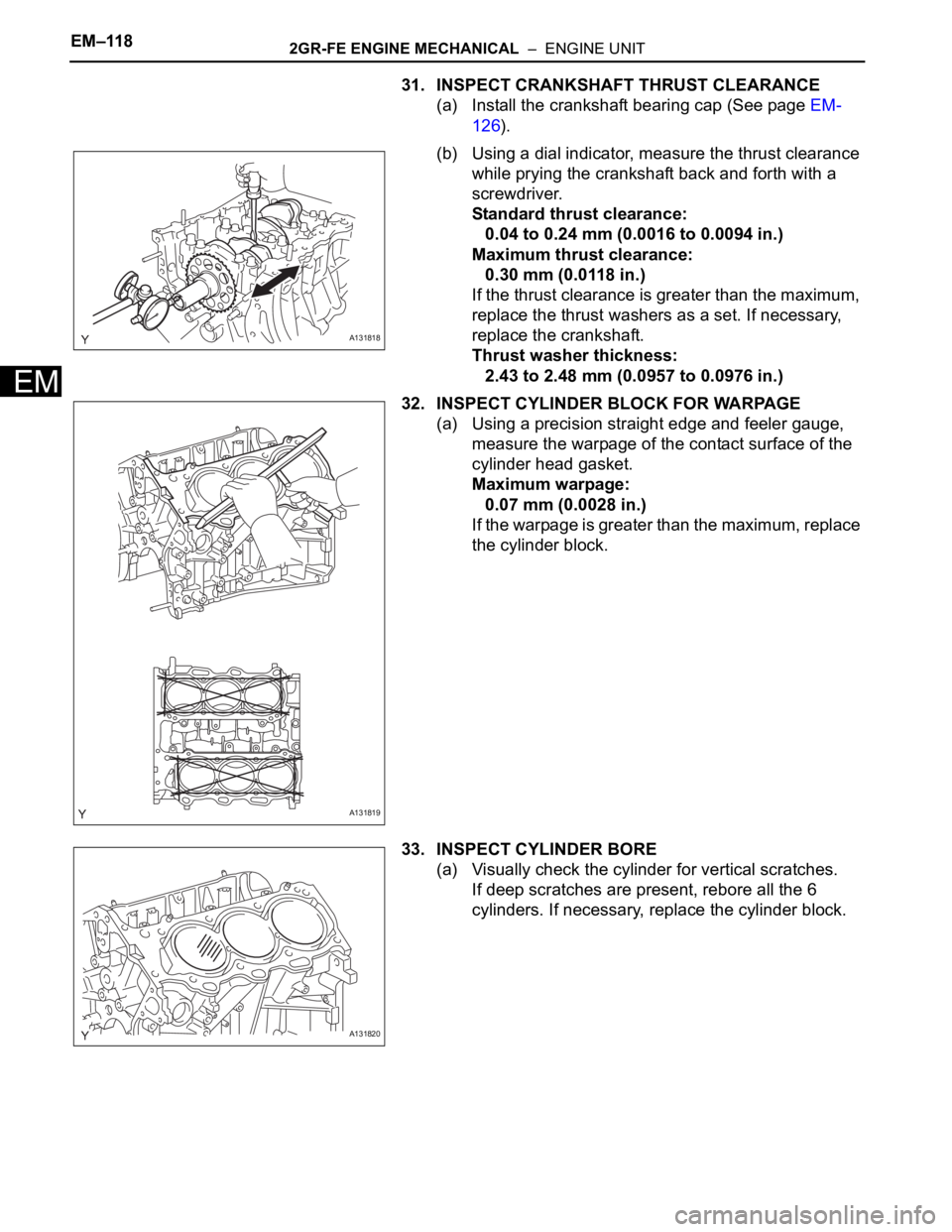
(b) Using a dial indicator, measure the thrust clearance
while prying the crankshaft back and forth with a
screwdriver.
Standard thrust clearance:
0.04 to 0.24 mm (0.0016 to 0.0094 in.)
Maximum thrust clearance:
0.30 mm (0.0118 in.)
If the thrust clearance is greater than the maximum,
replace the thrust washers as a set. If necessary,
replace the crankshaft.
Thrust washer thickness:
2.43 to 2.48 mm (0.0957 to 0.0976 in.)
32. INSPECT CYLINDER BLOCK FOR WARPAGE
(a) Using a precision straight edge and feeler gauge,
measure the warpage of the contact surface of the
cylinder head gasket.
Maximum warpage:
0.07 mm (0.0028 in.)
If the warpage is greater than the maximum, replace
the cylinder block.
33. INSPECT CYLINDER BORE
(a) Visually check the cylinder for vertical scratches.
If deep scratches are present, rebore all the 6
cylinders. If necessary, replace the cylinder block.
A131818
A131819
A131820
Page 927 of 3000
EM–1222GR-FE ENGINE MECHANICAL – ENGINE UNIT
EM
39. INSPECT CONNECTING ROD
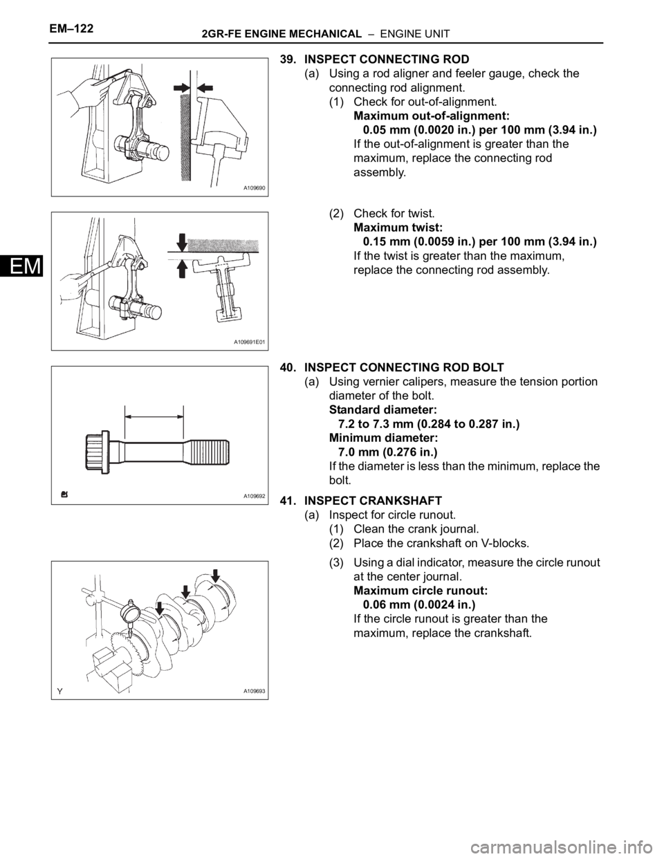
(a) Using a rod aligner and feeler gauge, check the
connecting rod alignment.
(1) Check for out-of-alignment.
Maximum out-of-alignment:
0.05 mm (0.0020 in.) per 100 mm (3.94 in.)
If the out-of-alignment is greater than the
maximum, replace the connecting rod
assembly.
(2) Check for twist.
Maximum twist:
0.15 mm (0.0059 in.) per 100 mm (3.94 in.)
If the twist is greater than the maximum,
replace the connecting rod assembly.
40. INSPECT CONNECTING ROD BOLT
(a) Using vernier calipers, measure the tension portion
diameter of the bolt.
Standard diameter:
7.2 to 7.3 mm (0.284 to 0.287 in.)
Minimum diameter:
7.0 mm (0.276 in.)
If the diameter is less than the minimum, replace the
bolt.
41. INSPECT CRANKSHAFT
(a) Inspect for circle runout.
(1) Clean the crank journal.
(2) Place the crankshaft on V-blocks.
(3) Using a dial indicator, measure the circle runout
at the center journal.
Maximum circle runout:
0.06 mm (0.0024 in.)
If the circle runout is greater than the
maximum, replace the crankshaft.
A109690
A109691E01
A109692
A109693
Page 928 of 3000
2GR-FE ENGINE MECHANICAL – ENGINE UNITEM–123
EM
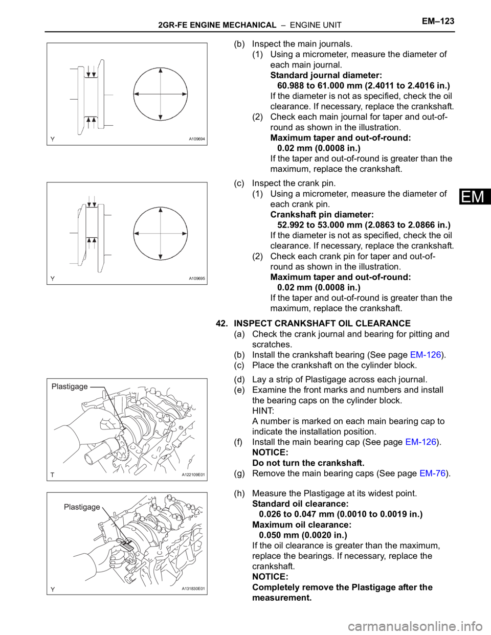
(b) Inspect the main journals.
(1) Using a micrometer, measure the diameter of
each main journal.
Standard journal diameter:
60.988 to 61.000 mm (2.4011 to 2.4016 in.)
If the diameter is not as specified, check the oil
clearance. If necessary, replace the crankshaft.
(2) Check each main journal for taper and out-of-
round as shown in the illustration.
Maximum taper and out-of-round:
0.02 mm (0.0008 in.)
If the taper and out-of-round is greater than the
maximum, replace the crankshaft.
(c) Inspect the crank pin.
(1) Using a micrometer, measure the diameter of
each crank pin.
Crankshaft pin diameter:
52.992 to 53.000 mm (2.0863 to 2.0866 in.)
If the diameter is not as specified, check the oil
clearance. If necessary, replace the crankshaft.
(2) Check each crank pin for taper and out-of-
round as shown in the illustration.
Maximum taper and out-of-round:
0.02 mm (0.0008 in.)
If the taper and out-of-round is greater than the
maximum, replace the crankshaft.
42. INSPECT CRANKSHAFT OIL CLEARANCE
(a) Check the crank journal and bearing for pitting and
scratches.
(b) Install the crankshaft bearing (See page EM-126).
(c) Place the crankshaft on the cylinder block.
(d) Lay a strip of Plastigage across each journal.
(e) Examine the front marks and numbers and install
the bearing caps on the cylinder block.
HINT:
A number is marked on each main bearing cap to
indicate the installation position.
(f) Install the main bearing cap (See page EM-126).
NOTICE:
Do not turn the crankshaft.
(g) Remove the main bearing caps (See page EM-76).
(h) Measure the Plastigage at its widest point.
Standard oil clearance:
0.026 to 0.047 mm (0.0010 to 0.0019 in.)
Maximum oil clearance:
0.050 mm (0.0020 in.)
If the oil clearance is greater than the maximum,
replace the bearings. If necessary, replace the
crankshaft.
NOTICE:
Completely remove the Plastigage after the
measurement.
A109694
A109695
A122109E01
A131830E01
Page 931 of 3000

2GR-FE ENGINE MECHANICAL – ENGINEEM–1
EM
ENGINE
ON-VEHICLE INSPECTION
1. INSPECT ENGINE COOLANT
(a) Inspect the engine coolant (See page CO-1).
2. INSPECT ENGINE OIL
(a) Inspect the engine oil (See page LU-1).
3. INSPECT BATTERY
(a) Inspect the battery (See page CH-5).
4. INSPECT AIR CLEANER FILTER ELEMENT SUB-
ASSEMBLY
(a) Remove the air cleaner filter element sub-assembly.
(b) Visually check that there is no dirt, blockage, and/or
damage to the air cleaner filter element.
HINT:
• If there is any dirt or a blockage in the air cleaner
filter element, clean it with compressed air.
• If any dirt or a blockage remains even after
cleaning the air cleaner filter element with
compressed air, replace it.
5. INSPECT SPARK PLUG
(a) Inspect the spark plugs (See page IG-5).
6. INSPECT VALVE LASH ADJUSTER NOISE
(a) Rev up the engine several times. Check that the
engine does not emit unusual noises.
If unusual noises occur, warm up the engine and
idle it for over 30 minutes. Then repeat this
procedure.
HINT:
If any defects or problems are found during the
inspection above, perform lash adjuster inspection
(See page EM-100).
7. INSPECT IGNITION TIMING
(a) Warm up the engine.
(b) When using the intelligent tester:
Check the ignition timing.
(1) Connect the intelligent tester to the DLC3.
(2) Enter DATA LIST mode with the intelligent
tester.
Ignition timing:
8 to 12
BTDC at idle
HINT:
Refer to the intelligent tester operator's manual
for help when selecting the DATA LIST.
C110200E02
Page 932 of 3000
EM–22GR-FE ENGINE MECHANICAL – ENGINE
EM
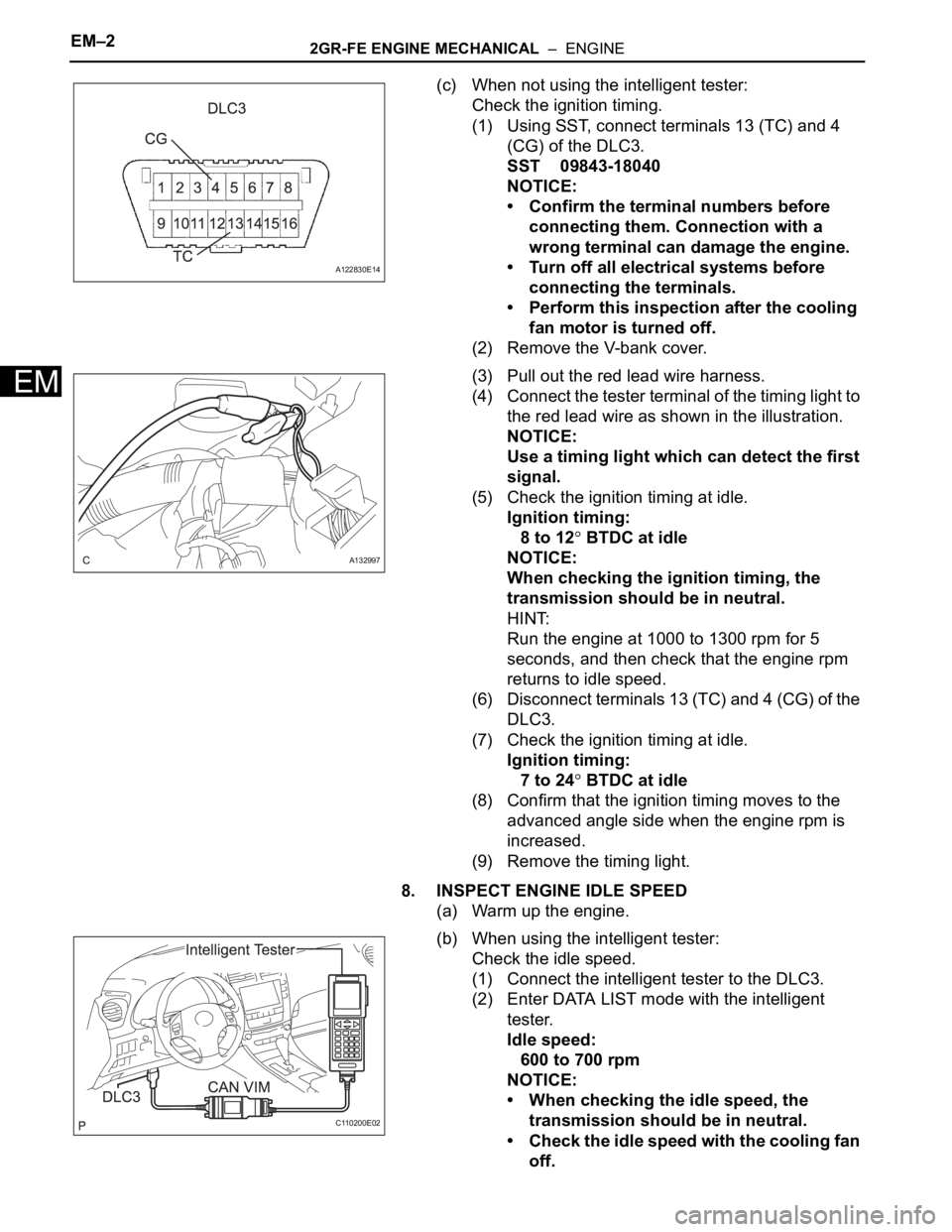
(c) When not using the intelligent tester:
Check the ignition timing.
(1) Using SST, connect terminals 13 (TC) and 4
(CG) of the DLC3.
SST 09843-18040
NOTICE:
• Confirm the terminal numbers before
connecting them. Connection with a
wrong terminal can damage the engine.
• Turn off all electrical systems before
connecting the terminals.
• Perform this inspection after the cooling
fan motor is turned off.
(2) Remove the V-bank cover.
(3) Pull out the red lead wire harness.
(4) Connect the tester terminal of the timing light to
the red lead wire as shown in the illustration.
NOTICE:
Use a timing light which can detect the first
signal.
(5) Check the ignition timing at idle.
Ignition timing:
8 to 12
BTDC at idle
NOTICE:
When checking the ignition timing, the
transmission should be in neutral.
HINT:
Run the engine at 1000 to 1300 rpm for 5
seconds, and then check that the engine rpm
returns to idle speed.
(6) Disconnect terminals 13 (TC) and 4 (CG) of the
DLC3.
(7) Check the ignition timing at idle.
Ignition timing:
7 to 24
BTDC at idle
(8) Confirm that the ignition timing moves to the
advanced angle side when the engine rpm is
increased.
(9) Remove the timing light.
8. INSPECT ENGINE IDLE SPEED
(a) Warm up the engine.
(b) When using the intelligent tester:
Check the idle speed.
(1) Connect the intelligent tester to the DLC3.
(2) Enter DATA LIST mode with the intelligent
tester.
Idle speed:
600 to 700 rpm
NOTICE:
• When checking the idle speed, the
transmission should be in neutral.
• Check the idle speed with the cooling fan
off.
A122830E14
A132997
C110200E02
Page 933 of 3000
2GR-FE ENGINE MECHANICAL – ENGINEEM–3
EM
• Switch off all accessories and air
conditioning before connecting the
intelligent tester.
HINT:
Refer to the intelligent tester operator's manual
for further details.
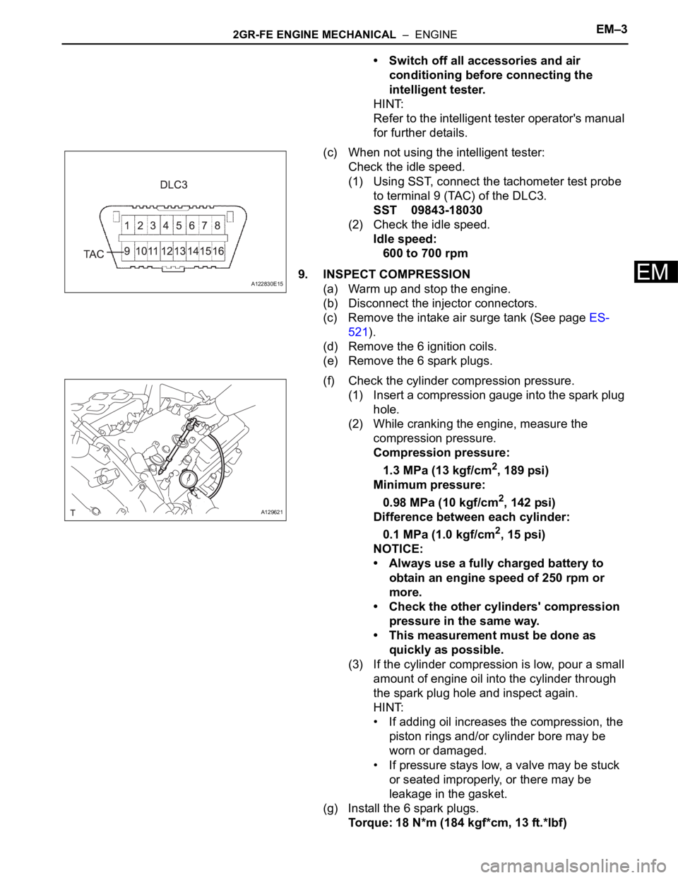
(c) When not using the intelligent tester:
Check the idle speed.
(1) Using SST, connect the tachometer test probe
to terminal 9 (TAC) of the DLC3.
SST 09843-18030
(2) Check the idle speed.
Idle speed:
600 to 700 rpm
9. INSPECT COMPRESSION
(a) Warm up and stop the engine.
(b) Disconnect the injector connectors.
(c) Remove the intake air surge tank (See page ES-
521).
(d) Remove the 6 ignition coils.
(e) Remove the 6 spark plugs.
(f) Check the cylinder compression pressure.
(1) Insert a compression gauge into the spark plug
hole.
(2) While cranking the engine, measure the
compression pressure.
Compression pressure:
1.3 MPa (13 kgf/cm
2, 189 psi)
Minimum pressure:
0.98 MPa (10 kgf/cm
2, 142 psi)
Difference between each cylinder:
0.1 MPa (1.0 kgf/cm
2, 15 psi)
NOTICE:
• Always use a fully charged battery to
obtain an engine speed of 250 rpm or
more.
• Check the other cylinders' compression
pressure in the same way.
• This measurement must be done as
quickly as possible.
(3) If the cylinder compression is low, pour a small
amount of engine oil into the cylinder through
the spark plug hole and inspect again.
HINT:
• If adding oil increases the compression, the
piston rings and/or cylinder bore may be
worn or damaged.
• If pressure stays low, a valve may be stuck
or seated improperly, or there may be
leakage in the gasket.
(g) Install the 6 spark plugs.
Torque: 18 N*m (184 kgf*cm, 13 ft.*lbf)
A122830E15
A129621