Page 1038 of 3000
2GR-FE ENGINE MECHANICAL – ENGINE UNITEM–91
EM
(b) Hold the hexagonal portion of the camshaft with a
wrench, and remove the 2 bolts and 2 camshaft
timing gear assemblies.
NOTICE:
• Be careful not to damage the cylinder head
with the wrench.
• Do not disassemble the camshaft timing gear
assemblies.
(c) Remove the No. 2 chain sub-assembly.
44. REMOVE NO. 3 CHAIN TENSIONER ASSEMBLY
(a) Remove the bolt and No. 3 chain tensioner
assembly.
45. REMOVE CAMSHAFT BEARING CAP (for Bank 2)
(a) Check that the camshafts are positioned as shown
in the illustration.
(b) Uniformly loosen and remove the 8 bearing cap
bolts in the sequence shown in the illustration.
A120658E01
A109722
A129706E01
A134891E03
Page 1043 of 3000
EM–962GR-FE ENGINE MECHANICAL – ENGINE UNIT
EM
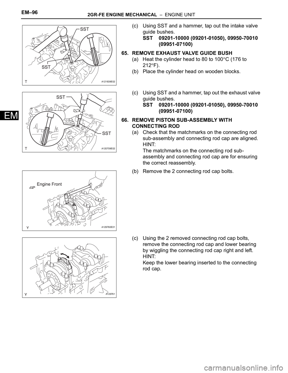
(c) Using SST and a hammer, tap out the intake valve
guide bushes.
SST 09201-10000 (09201-01050), 09950-70010
(09951-07100)
65. REMOVE EXHAUST VALVE GUIDE BUSH
(a) Heat the cylinder head to 80 to 100
C (176 to
212
F).
(b) Place the cylinder head on wooden blocks.
(c) Using SST and a hammer, tap out the exhaust valve
guide bushes.
SST 09201-10000 (09201-01050), 09950-70010
(09951-07100)
66. REMOVE PISTON SUB-ASSEMBLY WITH
CONNECTING ROD
(a) Check that the matchmarks on the connecting rod
sub-assembly and connecting rod cap are aligned.
HINT:
The matchmarks on the connecting rod sub-
assembly and connecting rod cap are for ensuring
the correct reassembly.
(b) Remove the 2 connecting rod cap bolts.
(c) Using the 2 removed connecting rod cap bolts,
remove the connecting rod cap and lower bearing
by wiggling the connecting rod cap right and left.
HINT:
Keep the lower bearing inserted to the connecting
rod cap.
A121839E02
A120709E02
A129760E01
A129761
Page 1045 of 3000
EM–982GR-FE ENGINE MECHANICAL – ENGINE UNIT
EM
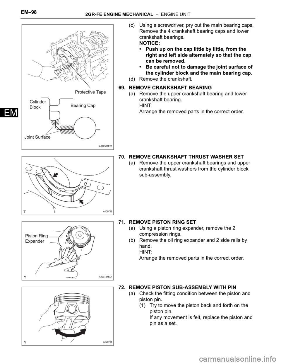
(c) Using a screwdriver, pry out the main bearing caps.
Remove the 4 crankshaft bearing caps and lower
crankshaft bearings.
NOTICE:
• Push up on the cap little by little, from the
right and left side alternately so that the cap
can be removed.
• Be careful not to damage the joint surface of
the cylinder block and the main bearing cap.
(d) Remove the crankshaft.
69. REMOVE CRANKSHAFT BEARING
(a) Remove the upper crankshaft bearing and lower
crankshaft bearing.
HINT:
Arrange the removed parts in the correct order.
70. REMOVE CRANKSHAFT THRUST WASHER SET
(a) Remove the upper crankshaft bearings and upper
crankshaft thrust washers from the cylinder block
sub-assembly.
71. REMOVE PISTON RING SET
(a) Using a piston ring expander, remove the 2
compression rings.
(b) Remove the oil ring expander and 2 side rails by
hand.
HINT:
Arrange the removed parts in the correct order.
72. REMOVE PISTON SUB-ASSEMBLY WITH PIN
(a) Check the fitting condition between the piston and
piston pin.
(1) Try to move the piston back and forth on the
piston pin.
If any movement is felt, replace the piston and
pin as a set.
A122567E01
A109726
A129724E01
A129725
Page 1047 of 3000
EM–1002GR-FE ENGINE MECHANICAL – ENGINE UNIT
EM
(e) Using solvent and a brush, thoroughly clean the
piston.
NOTICE:
Do not use a wire brush.
73. REMOVE NO. 1 OIL NOZZLE SUB-ASSEMBLY
(a) Using a 5 mm hexagon wrench, remove the bolts
and No. 1 oil nozzle sub-assembly.
(b) Check the 3 oil nozzles for damage or clogging.
If necessary, replace the No. 1 oil nozzle sub-
assembly.
74. CLEAN CYLINDER BLOCK
INSPECTION
1. INSPECT NO. 1 VALVE ROCKER ARM SUB-
ASSEMBLY
(a) Turn the roller by hand to check that it turns
smoothly.
HINT:
If the roller does not turn smoothly, replace the valve
rocker arm sub-assembly.
2. INSPECT VALVE LASH ADJUSTER ASSEMBLY
NOTICE:
• Keep the lash adjuster free of dirt and foreign
objects.
• Only use clean engine oil.
(a) Place the valve lash adjuster assembly into a
container filled with engine oil.
A129731
A120734
A125485
Page 1048 of 3000
2GR-FE ENGINE MECHANICAL – ENGINE UNITEM–101
EM
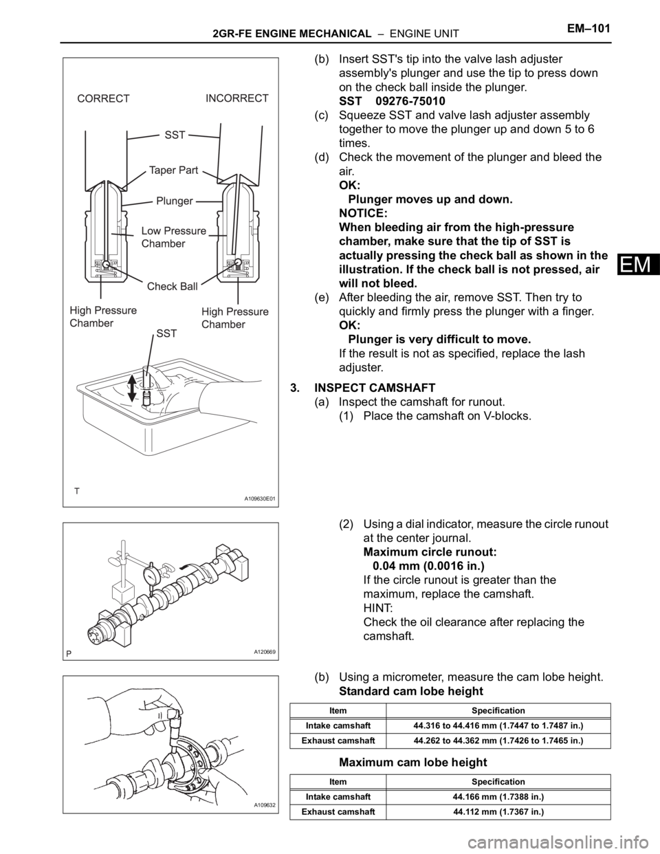
(b) Insert SST's tip into the valve lash adjuster
assembly's plunger and use the tip to press down
on the check ball inside the plunger.
SST 09276-75010
(c) Squeeze SST and valve lash adjuster assembly
together to move the plunger up and down 5 to 6
times.
(d) Check the movement of the plunger and bleed the
air.
OK:
Plunger moves up and down.
NOTICE:
When bleeding air from the high-pressure
chamber, make sure that the tip of SST is
actually pressing the check ball as shown in the
illustration. If the check ball is not pressed, air
will not bleed.
(e) After bleeding the air, remove SST. Then try to
quickly and firmly press the plunger with a finger.
OK:
Plunger is very difficult to move.
If the result is not as specified, replace the lash
adjuster.
3. INSPECT CAMSHAFT
(a) Inspect the camshaft for runout.
(1) Place the camshaft on V-blocks.
(2) Using a dial indicator, measure the circle runout
at the center journal.
Maximum circle runout:
0.04 mm (0.0016 in.)
If the circle runout is greater than the
maximum, replace the camshaft.
HINT:
Check the oil clearance after replacing the
camshaft.
(b) Using a micrometer, measure the cam lobe height.
Standard cam lobe height
Maximum cam lobe height
A109630E01
A120669
A109632
Item Specification
Intake camshaft 44.316 to 44.416 mm (1.7447 to 1.7487 in.)
Exhaust camshaft 44.262 to 44.362 mm (1.7426 to 1.7465 in.)
Item Specification
Intake camshaft 44.166 mm (1.7388 in.)
Exhaust camshaft 44.112 mm (1.7367 in.)
Page 1049 of 3000
EM–1022GR-FE ENGINE MECHANICAL – ENGINE UNIT
EM
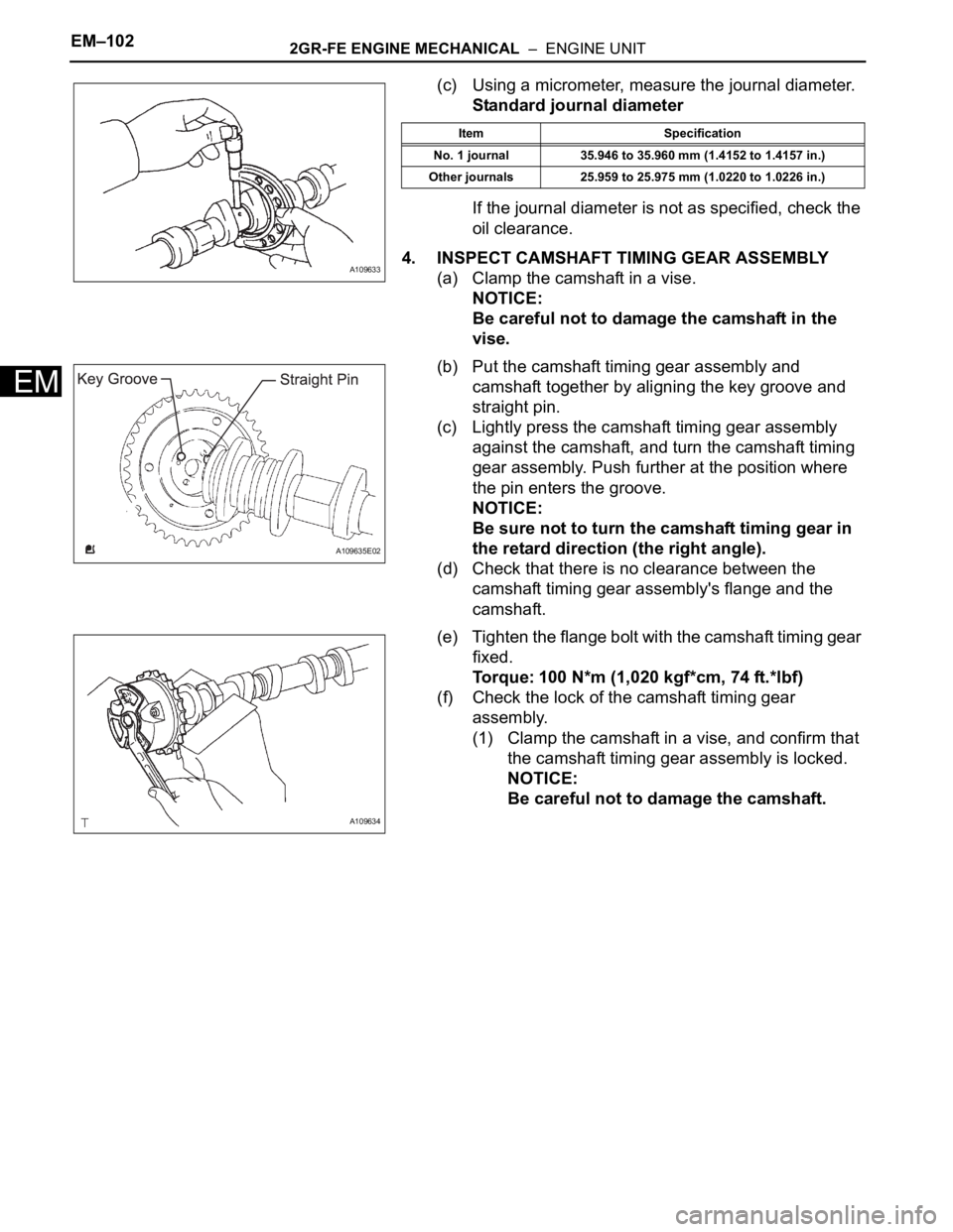
(c) Using a micrometer, measure the journal diameter.
Standard journal diameter
If the journal diameter is not as specified, check the
oil clearance.
4. INSPECT CAMSHAFT TIMING GEAR ASSEMBLY
(a) Clamp the camshaft in a vise.
NOTICE:
Be careful not to damage the camshaft in the
vise.
(b) Put the camshaft timing gear assembly and
camshaft together by aligning the key groove and
straight pin.
(c) Lightly press the camshaft timing gear assembly
against the camshaft, and turn the camshaft timing
gear assembly. Push further at the position where
the pin enters the groove.
NOTICE:
Be sure not to turn the camshaft timing gear in
the retard direction (the right angle).
(d) Check that there is no clearance between the
camshaft timing gear assembly's flange and the
camshaft.
(e) Tighten the flange bolt with the camshaft timing gear
fixed.
Torque: 100 N*m (1,020 kgf*cm, 74 ft.*lbf)
(f) Check the lock of the camshaft timing gear
assembly.
(1) Clamp the camshaft in a vise, and confirm that
the camshaft timing gear assembly is locked.
NOTICE:
Be careful not to damage the camshaft.
A109633
Item Specification
No. 1 journal 35.946 to 35.960 mm (1.4152 to 1.4157 in.)
Other journals 25.959 to 25.975 mm (1.0220 to 1.0226 in.)
A109635E02
A109634
Page 1050 of 3000
2GR-FE ENGINE MECHANICAL – ENGINE UNITEM–103
EM
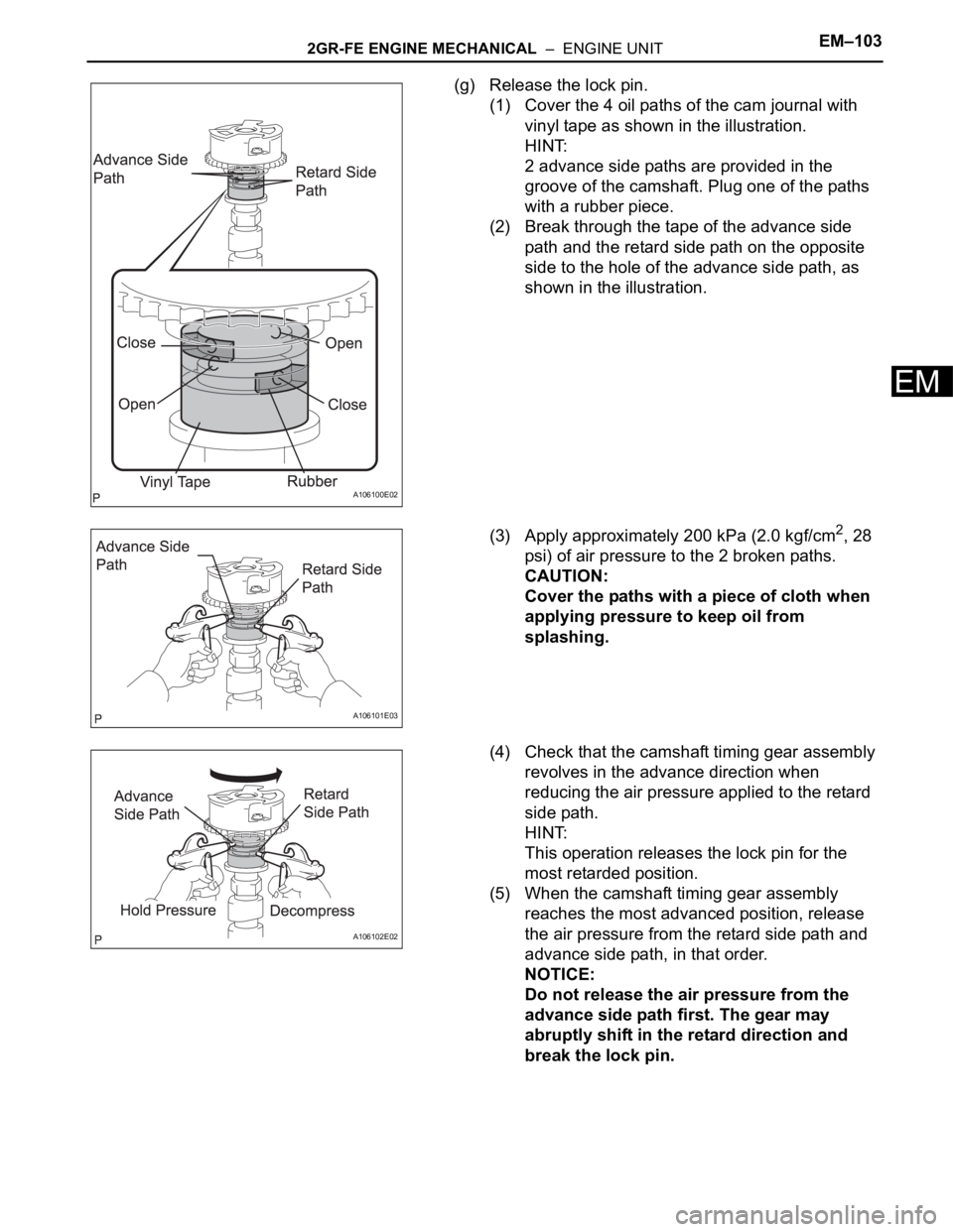
(g) Release the lock pin.
(1) Cover the 4 oil paths of the cam journal with
vinyl tape as shown in the illustration.
HINT:
2 advance side paths are provided in the
groove of the camshaft. Plug one of the paths
with a rubber piece.
(2) Break through the tape of the advance side
path and the retard side path on the opposite
side to the hole of the advance side path, as
shown in the illustration.
(3) Apply approximately 200 kPa (2.0 kgf/cm
2, 28
psi) of air pressure to the 2 broken paths.
CAUTION:
Cover the paths with a piece of cloth when
applying pressure to keep oil from
splashing.
(4) Check that the camshaft timing gear assembly
revolves in the advance direction when
reducing the air pressure applied to the retard
side path.
HINT:
This operation releases the lock pin for the
most retarded position.
(5) When the camshaft timing gear assembly
reaches the most advanced position, release
the air pressure from the retard side path and
advance side path, in that order.
NOTICE:
Do not release the air pressure from the
advance side path first. The gear may
abruptly shift in the retard direction and
break the lock pin.
A106100E02
A106101E03
A106102E02
Page 1051 of 3000
EM–1042GR-FE ENGINE MECHANICAL – ENGINE UNIT
EM
(h) Check for smooth rotation.
(1) Turn the camshaft timing gear assembly within
its movable range (21
) 2 or 3 times, but do not
turn it to the most retarded position. Make sure
that the gear turns smoothly.
NOTICE:
Do not use air pressure to perform the
smooth operation check.
(i) Check the lock in the most retarded position.
(1) Confirm that the camshaft timing gear
assembly is locked at the most retarded
position.
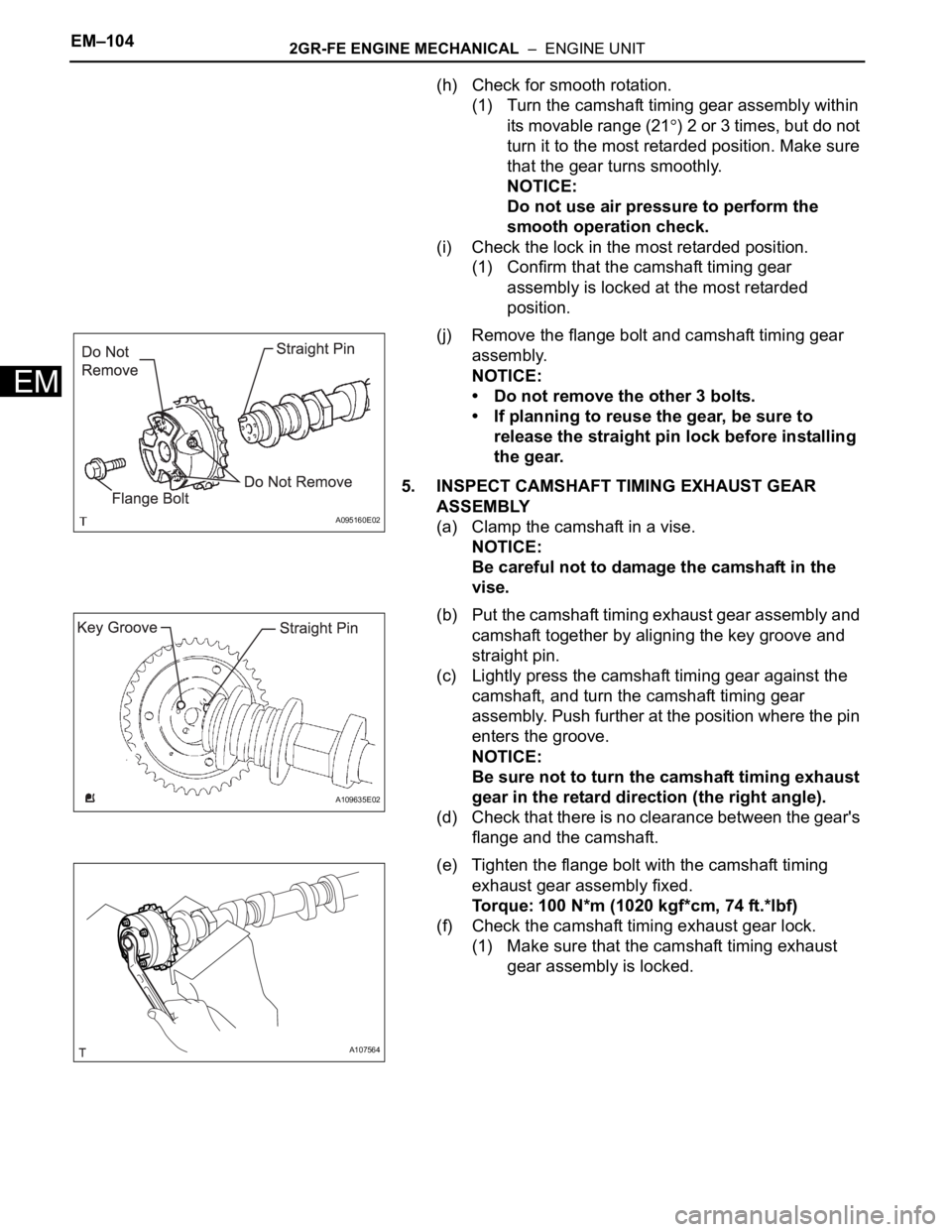
(j) Remove the flange bolt and camshaft timing gear
assembly.
NOTICE:
• Do not remove the other 3 bolts.
• If planning to reuse the gear, be sure to
release the straight pin lock before installing
the gear.
5. INSPECT CAMSHAFT TIMING EXHAUST GEAR
ASSEMBLY
(a) Clamp the camshaft in a vise.
NOTICE:
Be careful not to damage the camshaft in the
vise.
(b) Put the camshaft timing exhaust gear assembly and
camshaft together by aligning the key groove and
straight pin.
(c) Lightly press the camshaft timing gear against the
camshaft, and turn the camshaft timing gear
assembly. Push further at the position where the pin
enters the groove.
NOTICE:
Be sure not to turn the camshaft timing exhaust
gear in the retard direction (the right angle).
(d) Check that there is no clearance between the gear's
flange and the camshaft.
(e) Tighten the flange bolt with the camshaft timing
exhaust gear assembly fixed.
Torque: 100 N*m (1020 kgf*cm, 74 ft.*lbf)
(f) Check the camshaft timing exhaust gear lock.
(1) Make sure that the camshaft timing exhaust
gear assembly is locked.
A095160E02
A109635E02
A107564