Page 1132 of 3000
FU–202GR-FE FUEL – FUEL INJECTOR
FU
(e) Connect the union to check valve hose. (*1)
(f) Connect the No. 1 ventilation hose. (*2)
(g) Install the clamp and connect the throttle with motor
body assembly connector. (*3)
(h) Connect the vapor feed hose assembly. (*4)
(i) Connect the 2 water by-pass hoses to the throttle
with motor body assembly. (*5)
4. INSTALL AIR CLEANER CAP SUB-ASSEMBLY
(a) Install the 2 bolts and air cleaner cap sub-assembly.
(b) Connect the No. 2 ventilation hose and air cleaner
hose band.
(c) Connect the vacuum hose (EVAP) to the air cleaner
hose.
(d) Connect the 3 vacuum hoses.
5. ADD ENGINE COOLANT (See page CO-7)
6. CONNECT CABLE TO NEGATIVE BATTERY
TERMINAL
7. INSPECT FOR ENGINE COOLANT LEAK (See page
CO-1)
8. INSTALL NO. 1 ENGINE UNDER COVER
9. INSPECT FOR FUEL LEAK (See page FU-7)
A162431E01
A129464E10
A163204
A135113E01
A135112E01
Page 1141 of 3000
FU–202GR-FE FUEL – FUEL INJECTOR
FU
(e) Connect the union to check valve hose. (*1)
(f) Connect the No. 1 ventilation hose. (*2)
(g) Install the clamp and connect the throttle with motor
body assembly connector. (*3)
(h) Connect the vapor feed hose assembly. (*4)
(i) Connect the 2 water by-pass hoses to the throttle
with motor body assembly. (*5)
4. INSTALL AIR CLEANER CAP SUB-ASSEMBLY
(a) Install the 2 bolts and air cleaner cap sub-assembly.
(b) Connect the No. 2 ventilation hose and air cleaner
hose band.
(c) Connect the vacuum hose (EVAP) to the air cleaner
hose.
(d) Connect the 3 vacuum hoses.
5. ADD ENGINE COOLANT (See page CO-7)
6. CONNECT CABLE TO NEGATIVE BATTERY
TERMINAL
7. INSPECT FOR ENGINE COOLANT LEAK (See page
CO-1)
8. INSTALL NO. 1 ENGINE UNDER COVER
9. INSPECT FOR FUEL LEAK (See page FU-7)
A162431E01
A129464E10
A163204
A135113E01
A135112E01
Page 1175 of 3000

2GR-FE EMISSION CONTROL – EMISSION CONTROL SYSTEMEC–5
EC
ON-VEHICLE INSPECTION
1. INSPECT FUEL CUT RPM
(a) Increase the engine speed to at least 3500 rpm.
(b) Use a sound scope to check for injector operating
sounds.
(c) Check that when the throttle lever is released,
injector operating sounds stop momentarily (at 2500
rpm) and then resume (at 1400 rpm).
Standard
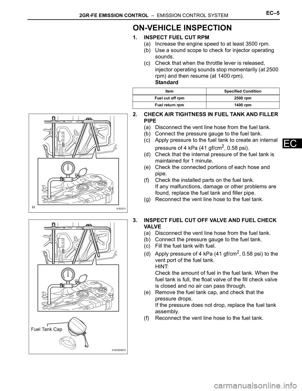
2. CHECK AIR TIGHTNESS IN FUEL TANK AND FILLER
PIPE
(a) Disconnect the vent line hose from the fuel tank.
(b) Connect the pressure gauge to the fuel tank.
(c) Apply pressure to the fuel tank to create an internal
pressure of 4 kPa (41 gf/cm
2, 0.58 psi).
(d) Check that the internal pressure of the fuel tank is
maintained for 1 minute.
(e) Check the connected portions of each hose and
pipe.
(f) Check the installed parts on the fuel tank.
If any malfunctions, damage or other problems are
found, replace the fuel tank and filler pipe.
(g) Reconnect the vent line hose to the fuel tank.
3. INSPECT FUEL CUT OFF VALVE AND FUEL CHECK
VA LV E
(a) Disconnect the vent line hose from the fuel tank.
(b) Connect the pressure gauge to the fuel tank.
(c) Fill the fuel tank with fuel.
(d) Apply pressure of 4 kPa (41 gf/cm
2, 0.58 psi) to the
vent port of the fuel tank.
HINT:
Check the amount of fuel in the fuel tank. When the
fuel tank is full, the float valve of the fill check valve
is closed and no air can pass through.
(e) Remove the fuel tank cap, and check that the
pressure drops.
If the pressure does not drop, replace the fuel tank
assembly.
(f) Reconnect the vent line hose to the fuel tank.
Item Specified Condition
Fuel cut off rpm 2500 rpm
Fuel return rpm 1400 rpm
A163311
A163504E01
Page 1176 of 3000
EC–62GR-FE EMISSION CONTROL – EMISSION CONTROL SYSTEM
EC
4. CHECK AIR INLET LINE
(a) Disconnect the air inlet line hose from the charcoal
canister.
(b) Check that air can flow freely into the air inlet line.
If air cannot flow freely into the air inlet line, repair or
replace it.
(c) Reconnect the air inlet line hose to the charcoal
canister.
5. VISUALLY INSPECT HOSES, CONNECTORS AND
GASKETS
(a) Check for cracks, leaks or damage.
HINT:
Removal or problems with the engine oil dipstick, oil
filler cap, PCV hose and other components may
cause the engine to run improperly. Disconnection,
looseness or cracks in the parts of the air induction
system between the throttle body and cylinder head
will allow air suction and cause the engine to run
improperly.
If necessary, replace any damaged parts.
A163329
A094394
Page 1192 of 3000

EC–182GR-FE EMISSION CONTROL – AIR FUEL RATIO SENSOR (for 2WD)
EC
ON-VEHICLE INSPECTION
HINT:
The type of ignition switch on this model differs according to
the specifications of the vehicle. For the expressions used in
this section, refer to the "EXPRESSIONS OF IGNITION
SWITCH" precaution (See page ES-1).
1. CHECK AIR FUEL RATIO COMPENSATION SYSTEM
(a) Connect the intelligent tester to the DLC3.
(b) Turn the ignition switch to the ON position.
(c) Select the following menu items: Data List / A/FS B1
S1 and O2S B1 S2.
(d) Warm up the A/F sensor with the engine speed at
2500 rpm for approximately 2 minutes.
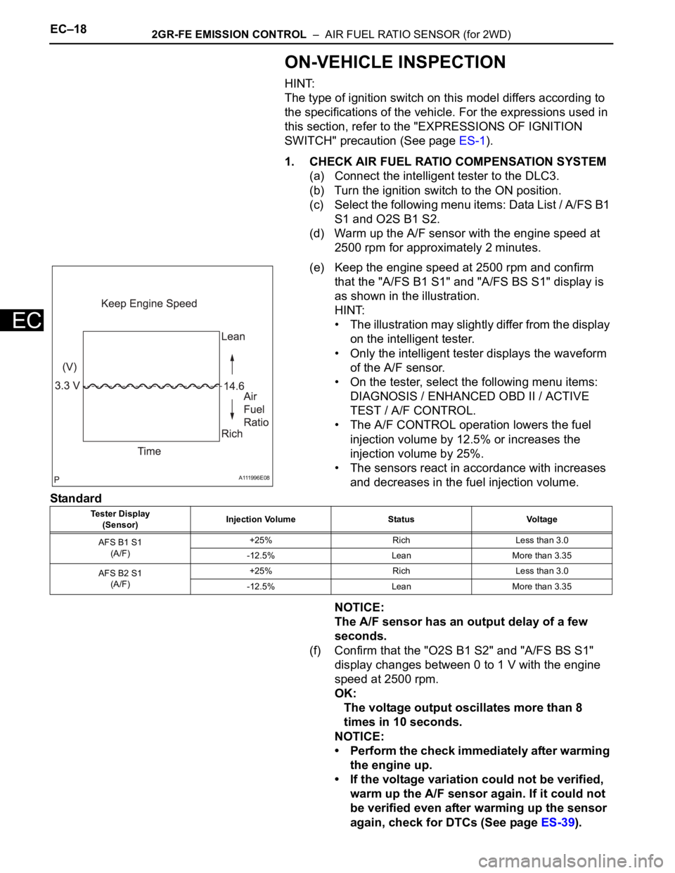
(e) Keep the engine speed at 2500 rpm and confirm
that the "A/FS B1 S1" and "A/FS BS S1" display is
as shown in the illustration.
HINT:
• The illustration may slightly differ from the display
on the intelligent tester.
• Only the intelligent tester displays the waveform
of the A/F sensor.
• On the tester, select the following menu items:
DIAGNOSIS / ENHANCED OBD II / ACTIVE
TEST / A/F CONTROL.
• The A/F CONTROL operation lowers the fuel
injection volume by 12.5% or increases the
injection volume by 25%.
• The sensors react in accordance with increases
and decreases in the fuel injection volume.
Standard
NOTICE:
The A/F sensor has an output delay of a few
seconds.
(f) Confirm that the "O2S B1 S2" and "A/FS BS S1"
display changes between 0 to 1 V with the engine
speed at 2500 rpm.
OK:
The voltage output oscillates more than 8
times in 10 seconds.
NOTICE:
• Perform the check immediately after warming
the engine up.
• If the voltage variation could not be verified,
warm up the A/F sensor again. If it could not
be verified even after warming up the sensor
again, check for DTCs (See page ES-39).
A111996E08
Tester Display
(Sensor)Injection Volume Status Voltage
AFS B1 S1
(A/F)+25% Rich Less than 3.0
-12.5% Lean More than 3.35
AFS B2 S1
(A/F)+25% Rich Less than 3.0
-12.5% Lean More than 3.35
Page 1196 of 3000

2GR-FE EMISSION CONTROL – AIR FUEL RATIO SENSOR (for 4WD)EC–25
EC
ON-VEHICLE INSPECTION
HINT:
The type of ignition switch on this model differs according to
the specifications of the vehicle. For the expressions used in
this section, refer to the "EXPRESSIONS OF IGNITION
SWITCH" precaution (See page ES-1).
1. CHECK AIR FUEL RATIO COMPENSATION SYSTEM
(a) Connect the intelligent tester to the DLC3.
(b) Turn the ignition switch to the ON position.
(c) Select the following menu items: Data List / A/FS B1
S1 and O2S B1 S2.
(d) Warm up the A/F sensor with the engine speed at
2500 rpm for approximately 2 minutes.
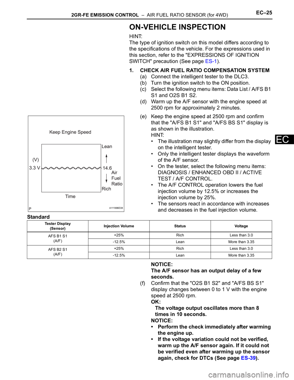
(e) Keep the engine speed at 2500 rpm and confirm
that the "A/FS B1 S1" and "A/FS BS S1" display is
as shown in the illustration.
HINT:
• The illustration may slightly differ from the display
on the intelligent tester.
• Only the intelligent tester displays the waveform
of the A/F sensor.
• On the tester, select the following menu items:
DIAGNOSIS / ENHANCED OBD II / ACTIVE
TEST / A/F CONTROL.
• The A/F CONTROL operation lowers the fuel
injection volume by 12.5% or increases the
injection volume by 25%.
• The sensors react in accordance with increases
and decreases in the fuel injection volume.
Standard
NOTICE:
The A/F sensor has an output delay of a few
seconds.
(f) Confirm that the "O2S B1 S2" and "A/FS BS S1"
display changes between 0 to 1 V with the engine
speed at 2500 rpm.
OK:
The voltage output oscillates more than 8
times in 10 seconds.
NOTICE:
• Perform the check immediately after warming
the engine up.
• If the voltage variation could not be verified,
warm up the A/F sensor again. If it could not
be verified even after warming up the sensor
again, check for DTCs (See page ES-39).
A111996E08
Tester Display
(Sensor)Injection Volume Status Voltage
AFS B1 S1
(A/F)+25% Rich Less than 3.0
-12.5% Lean More than 3.35
AFS B2 S1
(A/F)+25% Rich Less than 3.0
-12.5% Lean More than 3.35
Page 1238 of 3000

2GR-FE COOLING – COOLING SYSTEMCO–1
CO
COOLING SYSTEM
ON-VEHICLE INSPECTION
1. INSPECT FOR COOLANT LEAK
CAUTION:
Do not remove the radiator cap while the engine and
radiator are still hot. Pressurized, hot engine coolant
and steam may be released and cause serious
burns.
NOTICE:
Before performing each inspection, turn the A/C
switch OFF.
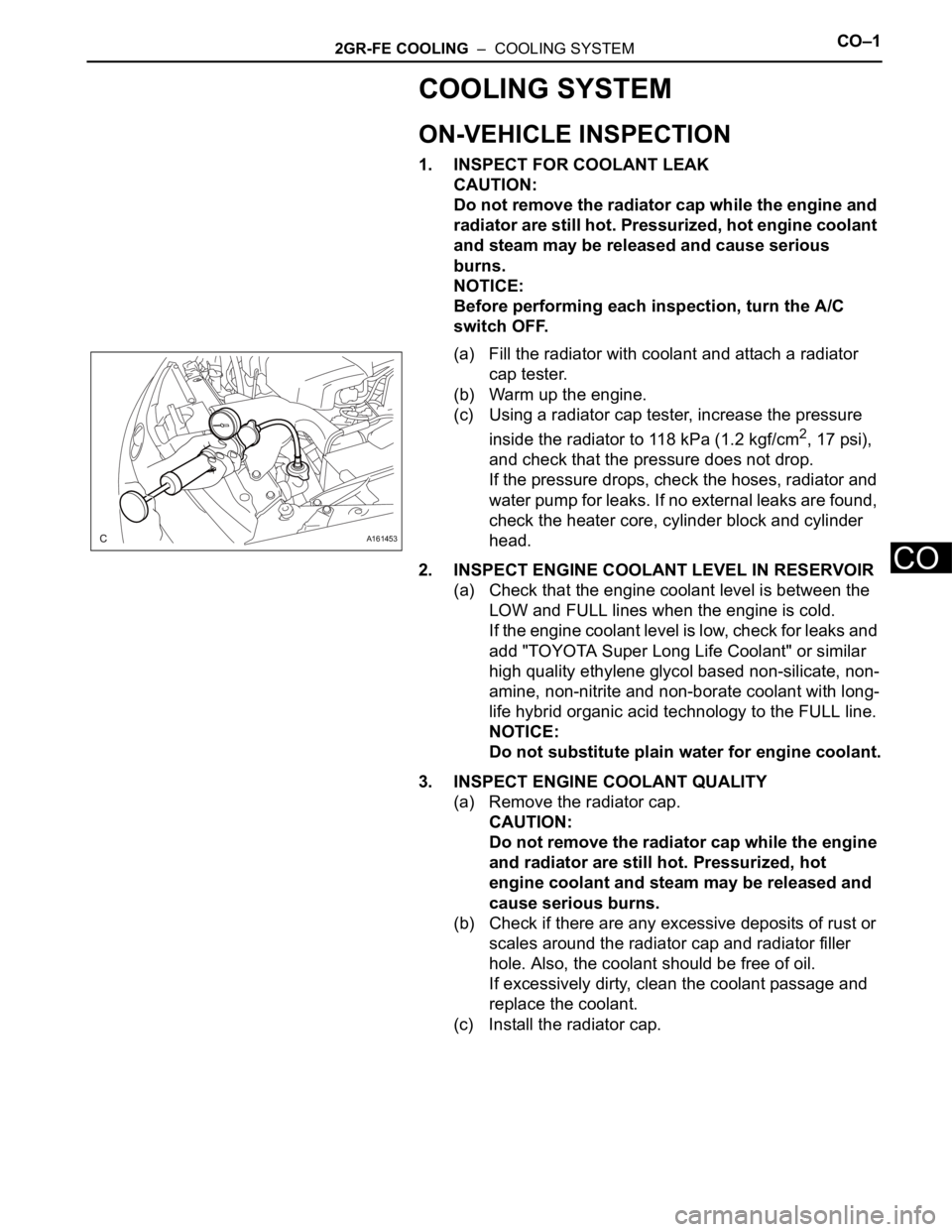
(a) Fill the radiator with coolant and attach a radiator
cap tester.
(b) Warm up the engine.
(c) Using a radiator cap tester, increase the pressure
inside the radiator to 118 kPa (1.2 kgf/cm
2, 17 psi),
and check that the pressure does not drop.
If the pressure drops, check the hoses, radiator and
water pump for leaks. If no external leaks are found,
check the heater core, cylinder block and cylinder
head.
2. INSPECT ENGINE COOLANT LEVEL IN RESERVOIR
(a) Check that the engine coolant level is between the
LOW and FULL lines when the engine is cold.
If the engine coolant level is low, check for leaks and
add "TOYOTA Super Long Life Coolant" or similar
high quality ethylene glycol based non-silicate, non-
amine, non-nitrite and non-borate coolant with long-
life hybrid organic acid technology to the FULL line.
NOTICE:
Do not substitute plain water for engine coolant.
3. INSPECT ENGINE COOLANT QUALITY
(a) Remove the radiator cap.
CAUTION:
Do not remove the radiator cap while the engine
and radiator are still hot. Pressurized, hot
engine coolant and steam may be released and
cause serious burns.
(b) Check if there are any excessive deposits of rust or
scales around the radiator cap and radiator filler
hole. Also, the coolant should be free of oil.
If excessively dirty, clean the coolant passage and
replace the coolant.
(c) Install the radiator cap.
A161453
Page 1242 of 3000

2GR-FE COOLING – COOLING FAN SYSTEMCO–5
CO
ON-VEHICLE INSPECTION
1. INSPECT COOLING FAN SYSTEM
(a) Put the vehicle in the following conditions:
(1) The engine switch is off.
(2) The coolant temperature is less than 95
C
(203
F).
(3) The battery voltage is between 9 and 14 V.
(4) The A/C switch is OFF.
(b) Clamp the 400 A probe of an ammeter over the M+
wire of each cooling fan motor.
(c) Turn the ignition switch to the ON position and wait
for approximately 10 seconds. Check that the fan
stops.
(d) Start the engine. Check that the fan stops with the
engine idling.
HINT:
• Make sure that the radiator engine coolant
temperature is less than 95
C (203F).
• Turn the A/C switch OFF.
(e) Check that the fan operates when the A/C switch is
turned ON (MAX COOL and the magnetic clutch is
operating).
Standard current
HINT:
The coolant temperature is less than 95
C (203F).
(f) Check that the fan operates when the engine
coolant temperature sensor connector is
disconnected.
Standard current
Item Specified Condition
No. 1 cooling fan motor 5 to 14 A
No. 2 cooling fan motor 4 to 12 A
Item Specified Condition
No. 1 cooling fan motor 5 to 19 A
No. 2 cooling fan motor 4 to 16 A