Page 1299 of 3000
2GR-FE LUBRICATION – LUBRICATION SYSTEMLU–1
LU
LUBRICATION SYSTEM
ON-VEHICLE INSPECTION
1. CHECK ENGINE OIL LEVEL
(a) Warm up the engine, stop it and wait 5 minutes. The
oil level should be between the dipstick's low level
mark and full level mark.
If the engine oil level is low, check for leakage and
add oil up to the full level mark.
NOTICE:
Do not add engine oil above the full level mark.
2. CHECK ENGINE OIL
(a) Check the engine oil for deterioration, water
contamination, discoloring or thinning.
If the oil is bad, replace the engine oil and engine oil
filter.
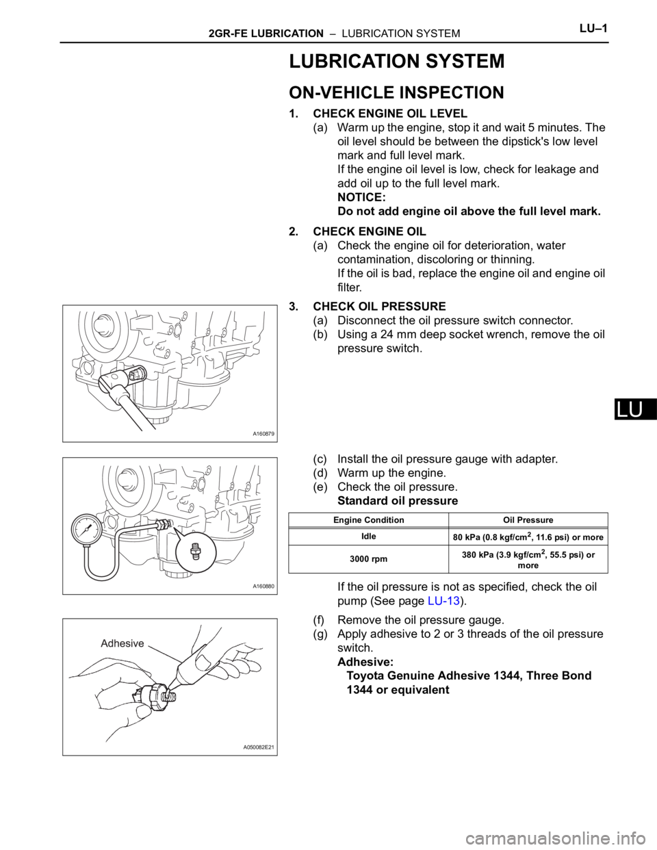
3. CHECK OIL PRESSURE
(a) Disconnect the oil pressure switch connector.
(b) Using a 24 mm deep socket wrench, remove the oil
pressure switch.
(c) Install the oil pressure gauge with adapter.
(d) Warm up the engine.
(e) Check the oil pressure.
Standard oil pressure
If the oil pressure is not as specified, check the oil
pump (See page LU-13).
(f) Remove the oil pressure gauge.
(g) Apply adhesive to 2 or 3 threads of the oil pressure
switch.
Adhesive:
Toyota Genuine Adhesive 1344, Three Bond
1344 or equivalent
A160879
A160880
Engine Condition Oil Pressure
Idle
80 kPa (0.8 kgf/cm
2, 11.6 psi) or more
3000 rpm380 kPa (3.9 kgf/cm
2, 55.5 psi) or
more
A050082E21
Page 1300 of 3000
LU–22GR-FE LUBRICATION – LUBRICATION SYSTEM
LU
(h) Using a 24 mm deep socket wrench, install the oil
pressure switch.
Torque: 15 N*m (153 kgf*cm, 11 ft.*lbf)
NOTICE:
Do not start the engine within 1 hour after
installation.
(i) Connect the oil pressure switch connector.
(j) Check for engine oil leaks.
A160879
Page 1304 of 3000
LU–62GR-FE LUBRICATION – OIL AND OIL FILTER
LU
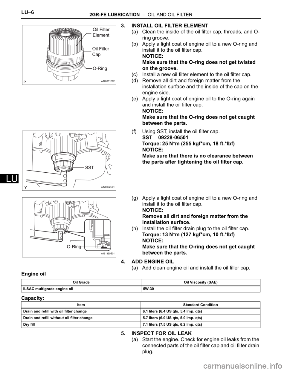
3. INSTALL OIL FILTER ELEMENT
(a) Clean the inside of the oil filter cap, threads, and O-
ring groove.
(b) Apply a light coat of engine oil to a new O-ring and
install it to the oil filter cap.
NOTICE:
Make sure that the O-ring does not get twisted
on the groove.
(c) Install a new oil filter element to the oil filter cap.
(d) Remove all dirt and foreign matter from the
installation surface and the inside of the cap on the
engine side.
(e) Apply a light coat of engine oil to the O-ring again
and install the oil filter cap.
NOTICE:
Make sure that the O-ring does not get caught
between the parts.
(f) Using SST, install the oil filter cap.
SST 09228-06501
Torque: 25 N*m (255 kgf*cm, 18 ft.*lbf)
NOTICE:
Make sure that there is no clearance between
the parts after tightening the oil filter cap.
(g) Apply a light coat of engine oil to a new O-ring and
install it to the oil filter cap.
NOTICE:
Remove all dirt and foreign matter from the
installation surface.
(h) Install the oil filter drain plug to the oil filter cap.
Torque: 13 N*m (127 kgf*cm, 10 ft.*lbf)
NOTICE:
Make sure that the O-ring does not get caught
between the parts.
4. ADD ENGINE OIL
(a) Add clean engine oil and install the oil filler cap.
Engine oil
Capacity:
5. INSPECT FOR OIL LEAK
(a) Start the engine. Check for engine oil leaks from the
connected parts of the oil filter cap and oil filter drain
plug.
A128001E02
A128002E01
A161390E01
Oil Grade Oil Viscosity (SAE)
ILSAC multigrade engine oil 5W-30
Item Standard Condition
Drain and refill with oil filter change 6.1 liters (6.4 US qts, 5.4 lmp. qts)
Drain and refill without oil filter change 5.7 liters (6.0 US qts, 5.0 lmp. qts)
Dry fill 7.1 liters (7.5 US qts, 6.2 lmp. qts)
Page 1305 of 3000
2GR-FE LUBRICATION – OIL PUMPLU–13
LU
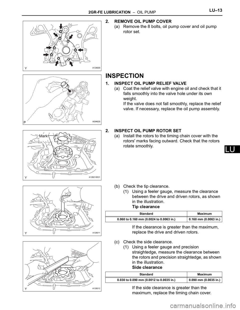
2. REMOVE OIL PUMP COVER
(a) Remove the 8 bolts, oil pump cover and oil pump
rotor set.
INSPECTION
1. INSPECT OIL PUMP RELIEF VALVE
(a) Coat the relief valve with engine oil and check that it
falls smoothly into the valve hole under its own
weight.
If the valve does not fall smoothly, replace the relief
valve. If necessary, replace the oil pump assembly.
2. INSPECT OIL PUMP ROTOR SET
(a) Install the rotors to the timing chain cover with the
rotors' marks facing outward. Check that the rotors
rotate smoothly.
(b) Check the tip clearance.
(1) Using a feeler gauge, measure the clearance
between the drive and driven rotors, as shown
in the illustration.
Tip clearance
If the clearance is greater than the maximum,
replace the drive and driven rotors.
(c) Check the side clearance.
(1) Using a feeler gauge and precision
straightedge, measure the clearance between
the rotors and precision straightedge, as shown
in the illustration.
Side clearance
If the side clearance is greater than the
maximum, replace the timing chain cover.
A128009
A094628
A128010E01
A128011
Standard Maximum
0.060 to 0.160 mm (0.0024 to 0.0063 in.) 0.160 mm (0.0063 in.)
A128012
Standard Maximum
0.030 to 0.090 mm (0.0012 to 0.0035 in.) 0.090 mm (0.0035 in.)
Page 1306 of 3000
LU–142GR-FE LUBRICATION – OIL PUMP
LU
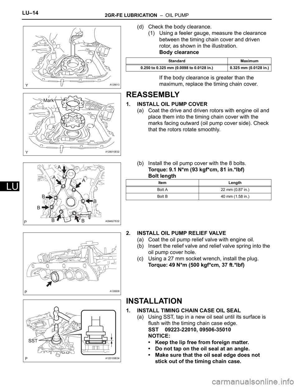
(d) Check the body clearance.
(1) Using a feeler gauge, measure the clearance
between the timing chain cover and driven
rotor, as shown in the illustration.
Body clearance
If the body clearance is greater than the
maximum, replace the timing chain cover.
REASSEMBLY
1. INSTALL OIL PUMP COVER
(a) Coat the drive and driven rotors with engine oil and
place them into the timing chain cover with the
marks facing outward (oil pump cover side). Check
that the rotors rotate smoothly.
(b) Install the oil pump cover with the 8 bolts.
Torque: 9.1 N*m (93 kgf*cm, 81 in.*lbf)
Bolt length
2. INSTALL OIL PUMP RELIEF VALVE
(a) Coat the oil pump relief valve with engine oil.
(b) Insert the relief valve and relief valve spring into the
oil pump cover hole.
(c) Using a 27 mm socket wrench, install the plug.
Torque: 49 N*m (500 kgf*cm, 37 ft.*lbf)
INSTALLATION
1. INSTALL TIMING CHAIN CASE OIL SEAL
(a) Using SST, tap in a new oil seal until its surface is
flush with the timing chain case edge.
SST 09223-22010, 09506-35010
NOTICE:
• Keep the lip free from foreign matter.
• Do not tap on the oil seal at an angle.
• Make sure that the oil seal edge does not
stick out of the timing chain case.
A128013
Standard Maximum
0.250 to 0.325 mm (0.0098 to 0.0128 in.) 0.325 mm (0.0128 in.)
A128010E02
A094627E02
Item Length
Bolt A 22 mm (0.87 in.)
Bolt B 40 mm (1.58 in.)
A128008
A125109E04
Page 1315 of 3000
IG–62GR-FE IGNITION – IGNITION COIL AND SPARK PLUG
IG
ON-VEHICLE INSPECTION
NOTICE:
In this section, the terms "cold" and "hot" refer to the
temperature of the coils. "Cold" means approximately -
10
C (14F) to 50C (122F). "Hot" means approximately
50
C (122F) to 100C (212F).
1. INSPECT IGNITION COIL ASSEMBLY
(a) Check for DTCs.
NOTICE:
If any DTC is present, perform troubleshooting
in accordance with the procedures for that DTC.
(b) Remove the ignition coil assembly and spark plug.
(See page IG-8).
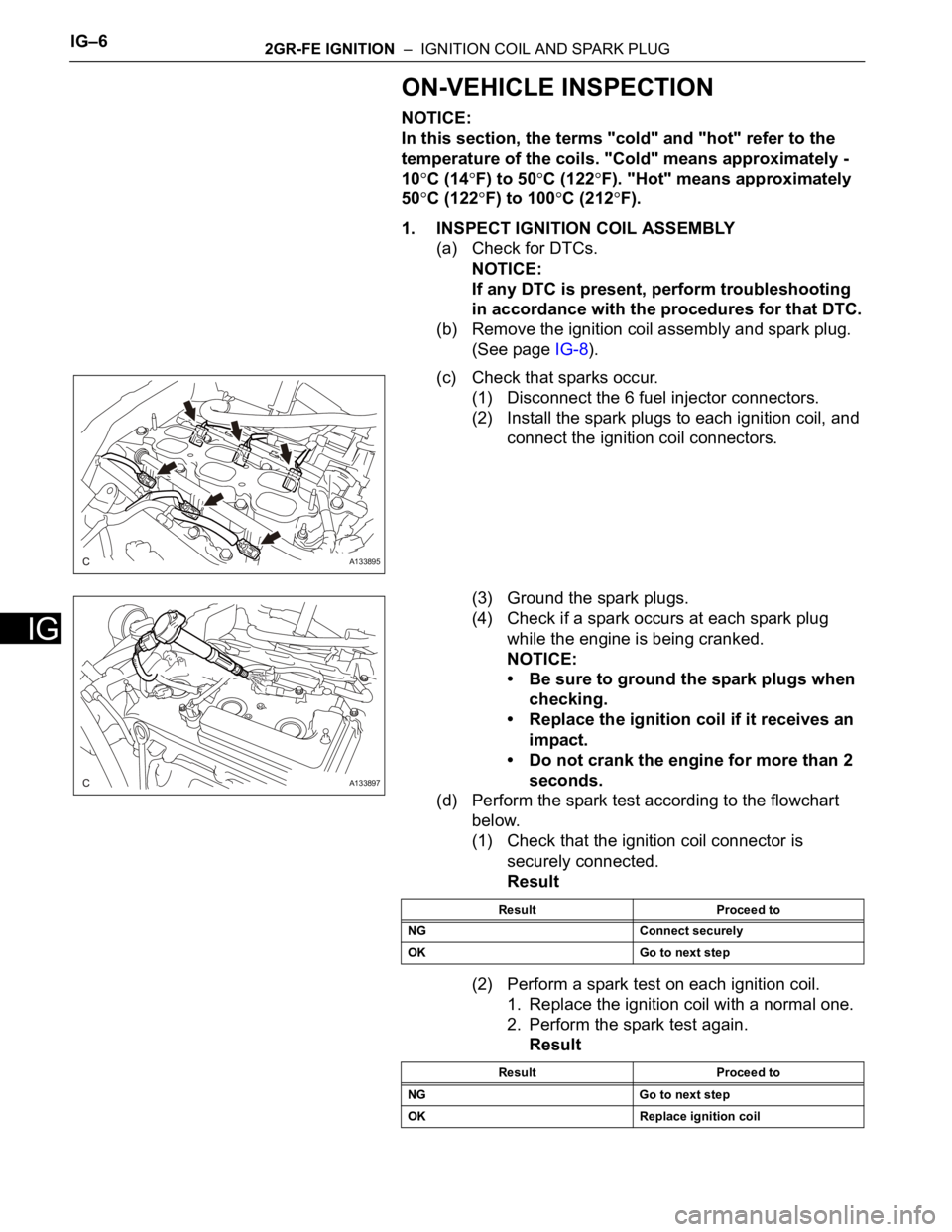
(c) Check that sparks occur.
(1) Disconnect the 6 fuel injector connectors.
(2) Install the spark plugs to each ignition coil, and
connect the ignition coil connectors.
(3) Ground the spark plugs.
(4) Check if a spark occurs at each spark plug
while the engine is being cranked.
NOTICE:
• Be sure to ground the spark plugs when
checking.
• Replace the ignition coil if it receives an
impact.
• Do not crank the engine for more than 2
seconds.
(d) Perform the spark test according to the flowchart
below.
(1) Check that the ignition coil connector is
securely connected.
Result
(2) Perform a spark test on each ignition coil.
1. Replace the ignition coil with a normal one.
2. Perform the spark test again.
Result
A133895
A133897
Result Proceed to
NG Connect securely
OK Go to next step
Result Proceed to
NG Go to next step
OK Replace ignition coil
Page 1316 of 3000
2GR-FE IGNITION – IGNITION COIL AND SPARK PLUGIG–7
IG
(3) Check the spark plug (See page EM-1).
Result
(4) Check the power supply to the ignition coil.
1. Turn the ignition switch to the ON position.
2. Check that there is battery voltage at the
ignition coil positive (+) terminal.
Result
(5) Measure the resistance of the crankshaft
position sensor (See page ES-514).
Result
(6) Check the IGT signal from the ECM (See page
ES-233)
Result
(e) Using a 16 mm (0.63 in.) plug wrench, install the
spark plugs.
Torque: 18 N*m (184 kgf*cm, 13 ft.*lbf)
(f) Connect the 6 fuel injector connectors.
(g) Install the ignition coil assembly (See page IG-10).
2. INSPECT SPARK PLUG
NOTICE:
• Never use a wire brush for cleaning.
• Never attempt to adjust the electrode gap on a
used spark plug.
(a) Check the electrode.
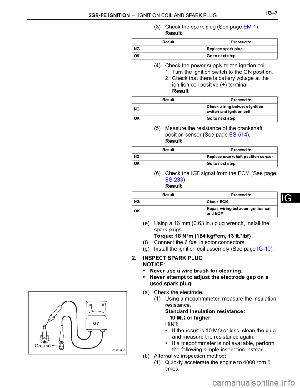
(1) Using a megohmmeter, measure the insulation
resistance.
Standard insulation resistance:
10 M
or higher
HINT:
• If the result is 10 M
or less, clean the plug
and measure the resistance again.
• If a megohmmeter is not available, perform
the following simple inspection instead.
(b) Alternative inspection method:
(1) Quickly accelerate the engine to 4000 rpm 5
times.
Result Proceed to
NG Replace spark plug
OK Go to next step
Result Proceed to
NGCheck wiring between ignition
switch and ignition coil
OK Go to next step
Result Proceed to
NG Replace crankshaft position sensor
OK Go to next step
Result Proceed to
NG Check ECM
OKRepair wiring between ignition coil
and ECM
I039522E10
Page 1317 of 3000
IG–82GR-FE IGNITION – IGNITION COIL AND SPARK PLUG
IG
(2) Remove the spark plugs.
(3) Visually check the spark plug.
If the electrode is dry, the spark plug is
functioning properly. If the electrode is damp,
proceed to the next step.
(c) Check the spark plug for any damage to its threads
and insulator. If there is damage, replace the spark
plug.
Recommended spark plug
NOTICE:
Use only the listed spark plug or equivalent to
ensure engine performance and smooth
driveability.
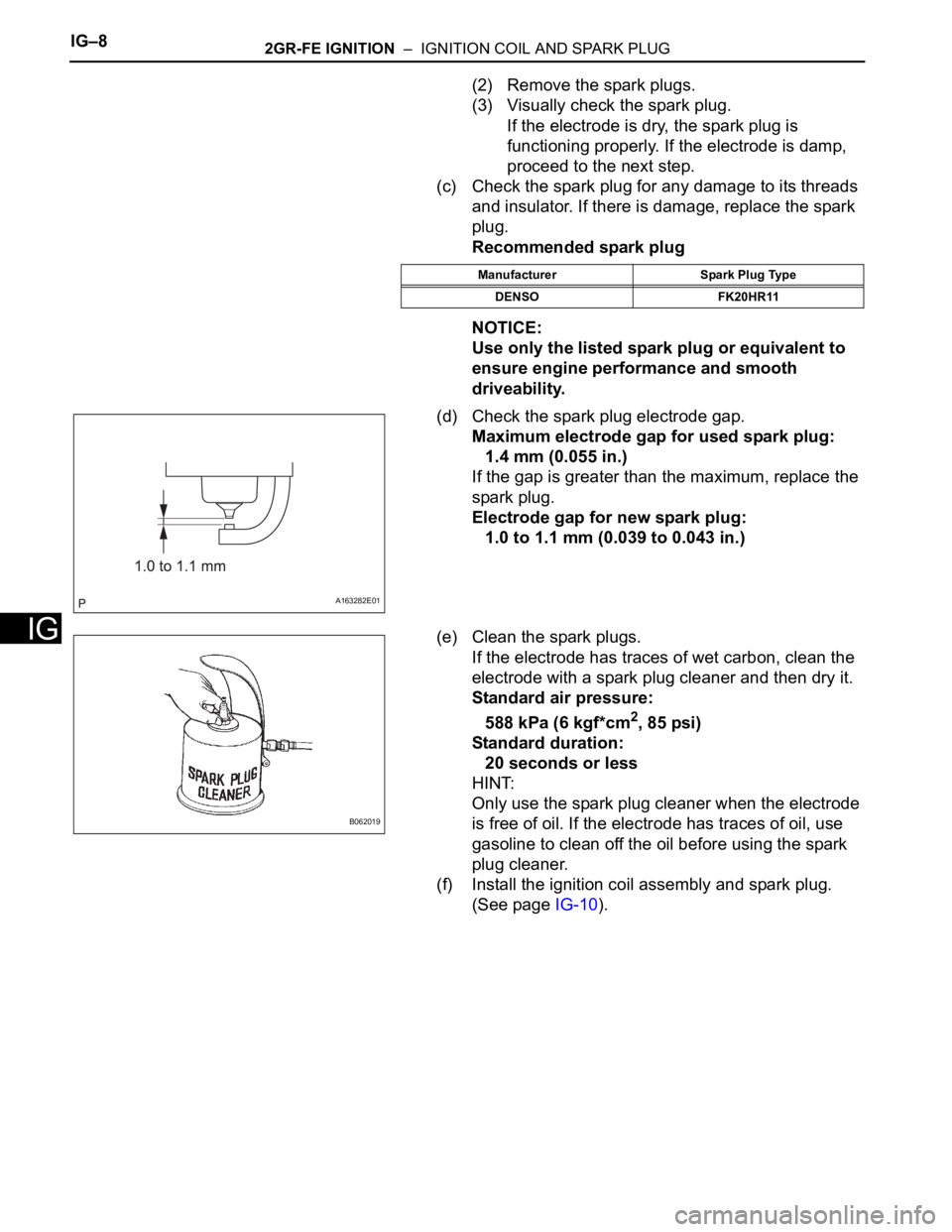
(d) Check the spark plug electrode gap.
Maximum electrode gap for used spark plug:
1.4 mm (0.055 in.)
If the gap is greater than the maximum, replace the
spark plug.
Electrode gap for new spark plug:
1.0 to 1.1 mm (0.039 to 0.043 in.)
(e) Clean the spark plugs.
If the electrode has traces of wet carbon, clean the
electrode with a spark plug cleaner and then dry it.
Standard air pressure:
588 kPa (6 kgf*cm
2, 85 psi)
Standard duration:
20 seconds or less
HINT:
Only use the spark plug cleaner when the electrode
is free of oil. If the electrode has traces of oil, use
gasoline to clean off the oil before using the spark
plug cleaner.
(f) Install the ignition coil assembly and spark plug.
(See page IG-10).
Manufacturer Spark Plug Type
DENSO FK20HR11
A163282E01
B062019