2007 TOYOTA SIENNA check engine
[x] Cancel search: check enginePage 1393 of 3000
AX–16U151E AUTOMATIC TRANSAXLE – AUTOMATIC TRANSAXLE SYSTEM
AX
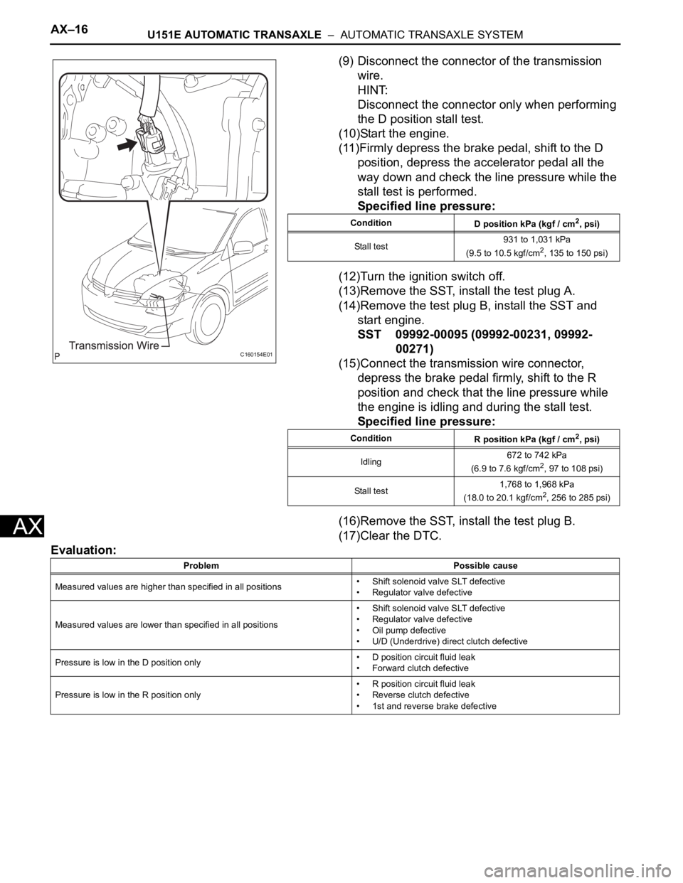
(9) Disconnect the connector of the transmission
wire.
HINT:
Disconnect the connector only when performing
the D position stall test.
(10)Start the engine.
(11)Firmly depress the brake pedal, shift to the D
position, depress the accelerator pedal all the
way down and check the line pressure while the
stall test is performed.
Specified line pressure:
(12)Turn the ignition switch off.
(13)Remove the SST, install the test plug A.
(14)Remove the test plug B, install the SST and
start engine.
SST 09992-00095 (09992-00231, 09992-
00271)
(15)Connect the transmission wire connector,
depress the brake pedal firmly, shift to the R
position and check that the line pressure while
the engine is idling and during the stall test.
Specified line pressure:
(16)Remove the SST, install the test plug B.
(17)Clear the DTC.
Evaluation:
C160154E01
Condition
D position kPa (kgf / cm2, psi)
Stall test931 to 1,031 kPa
(9.5 to 10.5 kgf/cm
2, 135 to 150 psi)
Condition
R position kPa (kgf / cm
2, psi)
Idling672 to 742 kPa
(6.9 to 7.6 kgf/cm
2, 97 to 108 psi)
Stall test1,768 to 1,968 kPa
(18.0 to 20.1 kgf/cm
2, 256 to 285 psi)
Problem Possible cause
Measured values are higher than specified in all positions• Shift solenoid valve SLT defective
• Regulator valve defective
Measured values are lower than specified in all positions• Shift solenoid valve SLT defective
• Regulator valve defective
• Oil pump defective
• U/D (Underdrive) direct clutch defective
Pressure is low in the D position only• D position circuit fluid leak
• Forward clutch defective
Pressure is low in the R position only• R position circuit fluid leak
• Reverse clutch defective
• 1st and reverse brake defective
Page 1397 of 3000

AX–20U151E AUTOMATIC TRANSAXLE – AUTOMATIC TRANSAXLE SYSTEM
AX
MONITOR DRIVE PATTERN
1. MONITOR DRIVE PATTERN FOR ECT TEST
(a) Perform this drive pattern as one method to
simulate the detection conditions of the ECT
malfunctions. (The DTCs may not be detected due
the actual driving conditions. And some codes may
not be detected through this drive pattern.)
HINT:
Preparation for driving
• Warm up the engine sufficiently. (Engine coolant
temperature is 60
C (140F) or higher)
• Drive the vehicle when the atmospheric
temperature is -10
C (14F) or higher.
(Malfunction is not detected when the
atmospheric temperature is less than -10
C
(14
F))
Driving note
• Drive the vehicle through all gears.
Stop
1st 2nd 3rd 4th 5th 5th
(lock-up ON).
• Repeat the above driving pattern three times or
more.
NOTICE:
• The monitor status can be checked using the
OBD II scan tool or intelligent tester. When
using the intelligent tester, monitor status
can be found in the "ENHANCED OBD II /
DATA LIST" or under "CARB OBD II".
• In the event that the drive pattern must be
interrupted (possibly due to traffic conditions
or other factors), the drive pattern can be
resumed and, in most cases, the monitor can
be completed.
• Perform this drive pattern on a level road as
much as possible and strictly observe the
posted speed limits and traffic laws while
driving.
Page 1399 of 3000
AX–22U151E AUTOMATIC TRANSAXLE – AUTOMATIC TRANSAXLE SYSTEM
AX
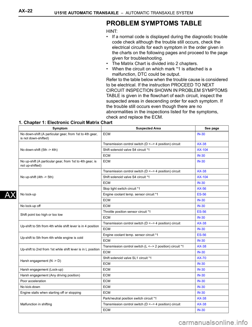
PROBLEM SYMPTOMS TABLE
HINT:
• If a normal code is displayed during the diagnostic trouble
code check although the trouble still occurs, check the
electrical circuits for each symptom in the order given in
the charts on the following pages and proceed to the page
given for troubleshooting.
• The Matrix Chart is divided into 2 chapters.
• When the circuit on which mark *1 is attached is a
malfunction, DTC could be output.
Refer to the table below when the trouble cause is considered
to be electrical. If the instruction PROCEED TO NEXT
CIRCUIT INSPECTION SHOWN IN PROBLEM SYMPTOMS
TABLE is given in the flowchart of each circuit, inspect the
suspected areas in descending order for each symptom. If
the trouble still occurs even though there are no
abnormalities in the inspections listed for the symptoms,
check and replace the ECM.
1. Chapter 1: Electronic Circuit Matrix Chart
Symptom Suspected Area See page
No down-shift (A particular gear, from 1st to 4th gear,
is not down-shifted)ECMIN-30
No down-shift (5th -> 4th)Transmission control switch (D <--> 4 position) circuitAX-38
Shift solenoid valve S4 circuit *1AX-104
ECMIN-30
No up-shift (A particular gear, from 1st to 4th gear, is
not up-shifted)ECMIN-30
No up-shift (4th -> 5th)Transmission control switch (D <--> 4 position) circuitAX-38
Shift solenoid valve S4 circuit *1AX-104
ECMIN-30
No lock-upStop light switch circuit *1AX-56
Engine coolant temp. sensor circuit *1ES-56
ECMIN-30
No lock-up off ECMIN-30
Shift point too high or too lowThrottle position sensor circuit *1ES-56
ECMIN-30
Up-shift to 5th from 4th while shift lever is in 4 positionTransmission control switch (D <--> 4 position) circuitAX-38
ECMIN-30
Up-shift to 5th from 4th while engine is coldEngine coolant temp. sensor circuit *1ES-56
ECMIN-30
Up-shift to 2nd from 1st while shift lever is in L positionTransmission control switch (L <--> 2 position) circuit *1AX-38
ECMIN-30
Harsh engagement (N -> D)Shift solenoid valve SL1 circuit *1AX-70
ECMIN-30
Harsh engagement (Lock-up) ECMIN-30
Harsh engagement (Any driving position) ECMIN-30
Poor acceleration ECMIN-30
No kick-down ECMIN-30
Engine stalls when starting off or stopping ECMIN-30
Malfunction in shiftingPark/neutral position switch circuit *1AX-38
Transmission control switch (D <--> 4 position) circuitAX-38
ECMIN-30
Page 1404 of 3000
AX–34U151E AUTOMATIC TRANSAXLE – AUTOMATIC TRANSAXLE SYSTEM
AX
CHECK MODE PROCEDURE
HINT:
Check mode has a higher sensitivity to malfunctions and can
detect malfunction that normal mode cannot detect. Check
mode can also detect all the malfunctions that normal mode
can detect. In check mode, DTCs are detected with 1-trip
detection logic.
1. DTC CHECK (CHECK MODE)
HINT:
Intelligent tester only: Compared to the normal mode, the
check mode is more sensitive for detecting malfunctions.
Furthermore, the same diagnostic items which are
detected in the normal mode can also be detected in the
check mode.
(a) Procedure for Check Mode using the intelligent
tester.
(1) Check the initial conditions.
• Battery positive voltage 11 V or more
• Throttle valve fully closed
• Transaxle in the P or N position
• A/C switch is off
(2) Turn the ignition switch off.
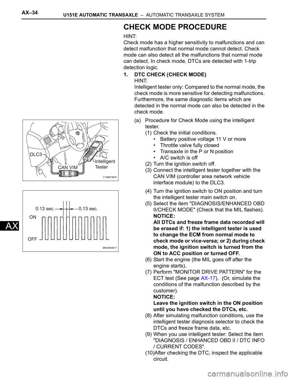
(3) Connect the intelligent tester together with the
CAN VIM (controller area network vehicle
interface module) to the DLC3.
(4) Turn the ignition switch to ON position and turn
the intelligent tester main switch on.
(5) Select the item "DIAGNOSIS/ENHANCED OBD
II/CHECK MODE" (Check that the MIL flashes).
NOTICE:
All DTCs and freeze frame data recorded will
be erased if: 1) the intelligent tester is used
to change the ECM from normal mode to
check mode or vice-versa; or 2) during check
mode, the ignition switch is turned from the
ON to ACC position or turned OFF.
(6) Start the engine (the MIL goes off after the
engine starts).
(7) Perform "MONITOR DRIVE PATTERN" for the
ECT test (See page AX-17). (Or, simulate the
conditions of the malfunction described by the
customer).
NOTICE:
Leave the ignition switch in the ON position
until you have checked the DTCs, etc.
(8) After simulating malfunction conditions, use the
intelligent tester diagnosis selector to check the
DTCs and freeze frame data, etc.
(9) When you use intelligent tester: Select the item
"DIAGNOSIS / ENHANCED OBD II / DTC INFO
/ CURRENT CODES".
(10)After checking the DTC, inspect the applicable
circuit.
C159873E01
BR03904E17
Page 1417 of 3000

U151E AUTOMATIC TRANSAXLE – AUTOMATIC TRANSAXLE SYSTEMAX–51
AX
MONITOR DESCRIPTION
These DTCs indicate an open or short in the automatic transmission fluid (ATF) temperature sensor (TFT
sensor) circuit. The automatic transmission fluid (ATF) temperature sensor converts ATF temperature to
an electrical resistance value. Based on the resistance, the ECM determines the ATF temperature, and
the ECM detects an opens or shorts in the ATF temperature circuit. If the resistance value of the ATF
temperature is less than 79
*1or more than 156 k *2, the ECM interprets this as a fault in the ATF
sensor or wiring. The ECM will turn on the MIL and store the DTC.
*1: 150
C (302F) or more is indicated regardless of the actual ATF temperature.
*2: -40
C (-40F) is indicated regardless of the actual ATF temperature.
HINT:
The ATF temperature can be checked on the OBD II scan tool or intelligent tester display.
MONITOR STRATEGY
TYPICAL ENABLING CONDITIONS
P0710: Range check (Chattering)
P0712: Range check (Low resistance)
P0713: Range check (High resistance)
TYPICAL MALFUNCTION THRESHOLDS
P0710: Range check (Chattering)
P0712: Range check (Low resistance)
P0713: Range check (High resistance)
P0712ATF temperature sensor resistance is less than 79
for 0.5 sec. or more (1-trip detection logic)• Short in ATF temperature sensor circuit
• Transmission wire (ATF temperature sensor)
•ECM
P0713ATF temperature sensor resistance is more than 156
k
when 15 minutes or more have elapsed after the
engine start
DTC is detected for 0.5 sec. or more (1-trip detection
logic)• Open in ATF temperature sensor circuit
• Transmission wire (ATF temperature sensor)
•ECM
Related DTCsP0710: ATF temperature sensor/Range check (Chattering)
P0712: ATF temperature sensor/Range check (Low resistance)
P0713: ATF temperature sensor/Range check (High resistance)
Required sensors/Components ATF temperature sensor (TFT sensor)
Frequency of operation Continuous
Duration 0.5 sec.
MIL operation Immediate
Sequence of operation None
The monitor will run whenever these DTCs are not present. None
The typical enabling condition is not available. -
The monitor will run whenever this DTC is not present. None
Time after engine start 15 min. or more
TFT (Transmission fluid temperature) sensor resistanceLess than 79
or
More than 156 k
TFT sensor resistanceLess than 79
TFT sensor resistance More than 156 k
DTC No. DTC Detection Condition Trouble Area
Page 1421 of 3000

U151E AUTOMATIC TRANSAXLE – AUTOMATIC TRANSAXLE SYSTEMAX–55
AX
DESCRIPTION
The ATF (Automatic Transmission Fluid) temperature sensor converts the fluid temperature into a
resistance value which is input into the ECM.
MONITOR DESCRIPTION
The ATF temperature sensor converts the ATF temperature to an electrical resistance value. Based on
the resistance, the ECM determines the ATF temperature and detects an open or short in the ATF
temperature circuit or a fault in the ATF temperature sensor.
After running the vehicle for a certain period, the ATF temperature should increase. If the ATF
temperature is below 20
C (68F) after running the vehicle for a certain period, the ECM interprets this as
a fault, and turns on the MIL.
When the ATF temperature is 110
C (230F) or more after 17 minutes of engine cold start, the ECM also
determines this as a fault, turns on the MIL, and stores the DTC.
MONITOR STRATEGY
TYPICAL ENABLING CONDITIONS
All:
Condition (A):
Condition (B):
DTC P0711Transmission Fluid Temperature Sensor "A"
Performance
DTC No. DTC Detection Condition Trouble Area
P0711(A) Both (a) and (b) are detected: (2-trip detection logic)
(a) Intake air and engine coolant temperatures are
more than -10
C (14F) at engine start
(b) After normal driving for over 19 min. and 9 km (6
mile) or more, ATF temp. is less than 20
C (68F)
(B) When engine coolant temp. is less than 35
C (95F)
at engine start, the ATF temp. is 110C (230F) or more
after 17 min. of engine start (2-trip detection logic).Transmission wire (ATF temperature sensor)
Related DTCs P0711: ATF temperature sensor/Rationality check
Required sensors/Components ATF temperature sensor (TFT sensor)
Frequency of operation Continuous
Duration3 sec.: Condition (A), (B), (C)
Continuous.: Condition (D)
MIL operation 2 driving cycles
Sequence of operation None
The monitor will run whenever this DTC is not present. None
TFT sensor circuitNot circuit malfunction
ECT sensor circuitNot circuit malfunction
IAT sensor circuitNot circuit malfunction
ETCSNot circuit malfunction
Time after engine start 18 min. and 20 sec.
Driving distance after engine start 9 km (5.6 mile) or more
IAT (Intake air temperature) (12 sec. after starting engine) -10
C (14F) or more
ECT (12 sec. after starting engine) -10
C (14F) or more
Time after engine start 30 min.
Driving distance after engine start 15 km (9.3 mile) or more
Page 1425 of 3000
U151E AUTOMATIC TRANSAXLE – AUTOMATIC TRANSAXLE SYSTEMAX–59
AX
DESCRIPTION
This sensor detects the rotation speed of the input turbine. By comparing the input turbine speed signal
(NT) with the counter gear speed sensor signal (NC), the ECM detects the shift timing of the gears and
appropriately controls the engine torque and hydraulic pressure according to various conditions. Thus,
providing smooth gear shift.
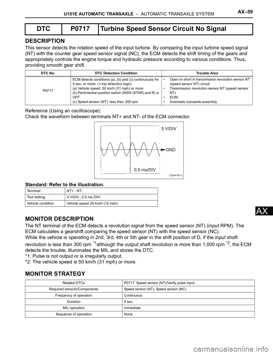
Reference (Using an oscilloscope):
Check the waveform between terminals NT+ and NT- of the ECM connector.
Standard: Refer to the illustration.
MONITOR DESCRIPTION
The NT terminal of the ECM detects a revolution signal from the speed sensor (NT) (input RPM). The
ECM calculates a gearshift comparing the speed sensor (NT) with the speed sensor (NC).
While the vehicle is operating in 2nd, 3rd, 4th or 5th gear in the shift position of D, if the input shaft
revolution is less than 300 rpm
*1although the output shaft revolution is more than 1,000 rpm *2, the ECM
detects the trouble, illuminates the MIL and stores the DTC.
*1: Pulse is not output or is irregularly output.
*2: The vehicle speed is 50 km/h (31 mph) or more.
MONITOR STRATEGY
DTC P0717 Turbine Speed Sensor Circuit No Signal
DTC No. DTC Detection Condition Trouble Area
P0717ECM detects conditions (a), (b) and (c) continuously for
5 sec. or more: (1-trip detection logic)
(a) Vehicle speed: 50 km/h (31 mph) or more
(b) Park/neutral position switch (NSW (STAR) and R) is
OFF
(c) Speed sensor (NT): less than 300 rpm• Open or short in transmission revolution sensor NT
(speed sensor NT) circuit
• Transmission revolution sensor NT (speed sensor
NT)
•ECM
• Automatic transaxle assembly
Te r m i n a l N T + - N T -
Tool setting 5 V/DIV., 0.5 ms./DIV.
Vehicle condition Vehicle speed 20 km/h (12 mph)
Related DTCs P0717: Speed sensor (NT)/Verify pulse input
Required sensors/Components Speed sensor (NT), Speed sensor (NC)
Frequency of operation Continuous
Duration 5 sec.
MIL operation Immediate
Sequence of operation None
C053419E13
Page 1435 of 3000
U151E AUTOMATIC TRANSAXLE – AUTOMATIC TRANSAXLE SYSTEMAX–69
AX
INSPECTION PROCEDURE
HINT:
Using the intelligent tester to perform ACTIVE TEST allows relays, VSVs, actuators and other items to be
operated without removing any parts. This non-intrusive functional inspection can be very useful because
intermittent operation may be discovered before parts or wiring is disturbed. Performing ACTIVE TEST
early in troubleshooting is one way to save diagnostic time. DATA LIST information can be displayed while
performing ACTIVE TEST.
1. PERFORM ACTIVE TEST
(a) Warm up the engine.
(b) Turn the ignition switch off.
(c) Connect the intelligent tester together with the CAN VIM (controller area network vehicle
interface module) to the DLC3.
(d) Turn the ignition switch to the ON position.
(e) Turn on the tester.
(f) Select the item "DIAGNOSIS / ENHANCED OBD II / ACTIVE TEST".
(g) According to the display on the tester, perform the "ACTIVE TEST".
HINT:
• This test can be conducted when the vehicle speed is 60 km/h (37 mph) or more.
• This test can be conducted in the 5th gear.
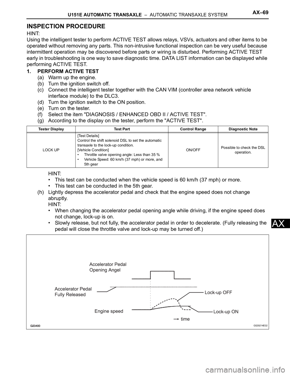
(h) Lightly depress the accelerator pedal and check that the engine speed does not change
abruptly.
HINT:
• When changing the accelerator pedal opening angle while driving, if the engine speed does
not change, lock-up is on.
• Slowly release, but not fully, the accelerator pedal in order to decelerate. (Fully releasing the
pedal will close the throttle valve and lock-up may be turned off.)
Tester Display Test Part Control Range Diagnostic Note
LOCK UP[Test Details]
Control the shift solenoid DSL to set the automatic
transaxle to the lock-up condition.
[Vehicle Condition]
• Throttle valve opening angle: Less than 35 %
• Vehicle Speed: 60 km/h (37 mph) or more, and
5th gearON/OFFPossible to check the DSL
operation.
G029214E02