Page 17 of 148
INTAKE MANIFOLD COLLECTOR
EM-17
C
D
E
F
G
H
I
J
K
L
MA
EM
Revision: 2006 November2007 350Z
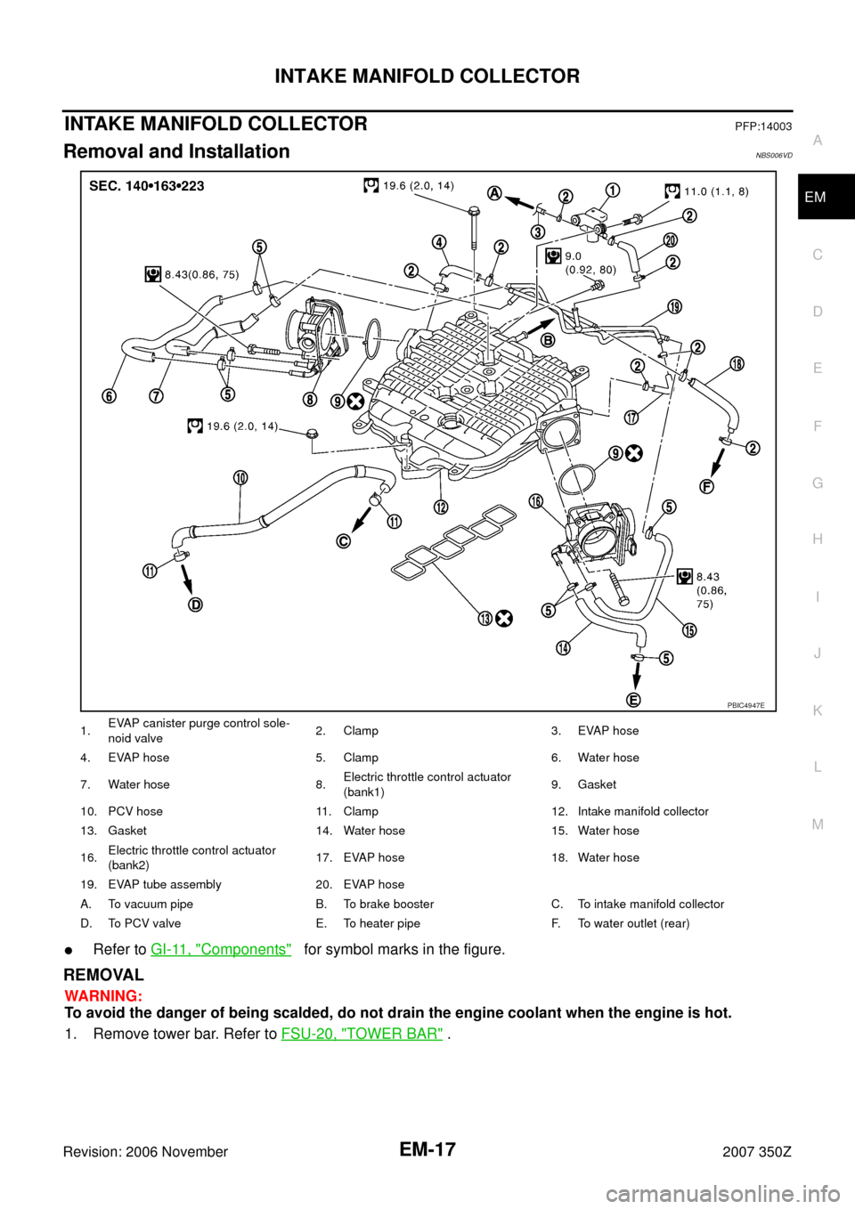
INTAKE MANIFOLD COLLECTORPFP:14003
Removal and InstallationNBS006VD
�Refer to GI-11, "Components" for symbol marks in the figure.
REMOVAL
WARNING:
To avoid the danger of being scalded, do not drain the engine coolant when the engine is hot.
1. Remove tower bar. Refer to FSU-20, "
TOWER BAR" .
1.EVAP canister purge control sole-
noid valve2. Clamp 3. EVAP hose
4. EVAP hose 5. Clamp 6. Water hose
7. Water hose 8.Electric throttle control actuator
(bank1)9. Gasket
10. PCV hose 11. Clamp 12. Intake manifold collector
13. Gasket 14. Water hose 15. Water hose
16.Electric throttle control actuator
(bank2)17. EVAP hose 18. Water hose
19. EVAP tube assembly 20. EVAP hose
A. To vacuum pipe B. To brake booster C. To intake manifold collector
D. To PCV valve E. To heater pipe F. To water outlet (rear)
PBIC4947E
Page 18 of 148
 (2) with power tool.
3. Remove air cleaner case and air duct (RH, LH). Refer to EM-15, \"
AIR CLEANER AND AIR")
EM-18
INTAKE MANIFOLD COLLECTOR
Revision: 2006 November2007 350Z
2. Remove engine cover (1) (2) with power tool.
3. Remove air cleaner case and air duct (RH, LH). Refer to EM-15, "
AIR CLEANER AND AIR DUCT" .
4. Remove electric throttle control actuator (bank1, bank2) as follows:
NOTE:
When removing only intake manifold collector, move electric throttle control actuator without disconnect-
ing water hose.
a. Drain engine coolant.
CAUTION:
Perform this step when engine is cold.
b. Disconnect water hoses from electric throttle control actuator. When engine coolant is not drained from
radiator, attach plug to water hoses to prevent engine coolant leakage.
CAUTION:
Do not spill engine coolant on drive belt.
c. Disconnect harness connector.
d. Loosen mounting bolts in reverse order as shown in the figure.
CAUTION:
�Handle carefully to avoid any shock to electric throttle
control actuator.
�Do not disassemble.
NOTE:
�Figure shows electric throttle control actuator (bank1) viewed
from the air duct side.
�Viewed from the air duct side, order of loosening mounting
bolts of electric throttle control actuator (bank2) is the same
as that of the electric throttle control actuator (bank1).
5. Disconnect vacuum hose, PCV hose and EVAP hose from intake manifold collector.
6. Remove EVAP canister purge volume control solenoid valve and EVAP tube assembly from intake mani-
fold collector.
PBIC4987E
PBIC4948E
Page 19 of 148

INTAKE MANIFOLD COLLECTOR
EM-19
C
D
E
F
G
H
I
J
K
L
MA
EM
Revision: 2006 November2007 350Z
7. Loosen mounting bolts with power tool in reverse order as
shown in the figure to remove intake manifold collector.
CAUTION:
Cover engine openings to avoid entry of foreign materials.
8. Remove PCV hose [between intake manifold collector and rocker cover (right bank)].
INSTALLATION
Note the following, and install in the reverse order of removal.
Intake Manifold Collector
If stud bolts were removed, install them and tighten to the specified torque below.
�Tighten mounting bolts in numerical order as shown in the fig-
ure.
NOTE:
Tighten mounting bolts to secure gasket and intake manifold col-
lector.
Water Hose
�Insert hose by 27 to 32 mm (1.06 to 1.26 in) from connector end.
�Clamp hose at location of 3 to 7 mm (0.12 to 0.28 in) from hose end.
Electric Throttle Control Actuator
�Install in the reverse order of removal.
�Tighten mounting bolts in numerical order as shown in the fig-
ure.
CAUTION:
�Handle carefully to avoid any shock to electric throttle
control actuator.
�Do not disassemble.
�The figure shows the electric throttle control actuator
(bank1) viewed from the air duct side.
�Viewed from the air duct side, order of tightening mount-
ing bolts of electric throttle control actuator (bank2) is
the same as that of the electric throttle control actuator
(bank1).
�Perform the “Throttle Valve Closed Position Learning” when harness connector of electric throttle control
actuator is disconnected. Refer to EC-77, "
Throttle Valve Closed Position Learning" .
�Perform the “Idle Air Volume Learning” and “Throttle Valve Closed Position Learning” when electric throt-
tle control actuator is replaced. Refer to EC-77, "
Idle Air Volume Learning" .
: Engine front
PBIC4949E
: 10.8 N·m (1.1 kg-m, 8 ft-lb)
: Engine front
PBIC4949E
PBIC4948E
Page 20 of 148
EM-20
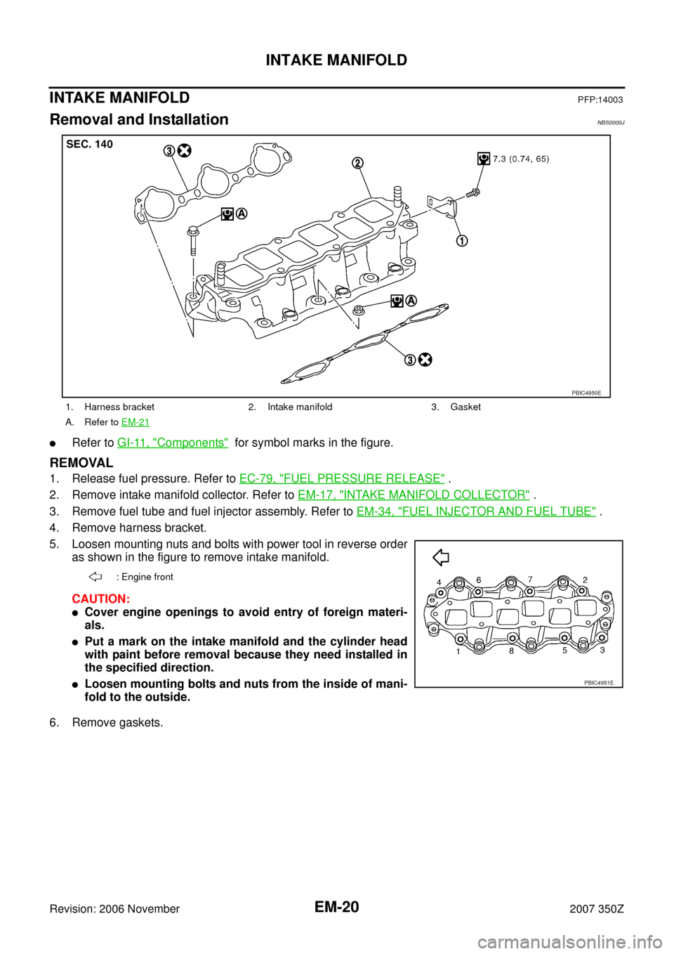
INTAKE MANIFOLD
Revision: 2006 November2007 350Z
INTAKE MANIFOLDPFP:14003
Removal and InstallationNBS0000J
�Refer to GI-11, "Components" for symbol marks in the figure.
REMOVAL
1. Release fuel pressure. Refer to EC-79, "FUEL PRESSURE RELEASE" .
2. Remove intake manifold collector. Refer to EM-17, "
INTAKE MANIFOLD COLLECTOR" .
3. Remove fuel tube and fuel injector assembly. Refer to EM-34, "
FUEL INJECTOR AND FUEL TUBE" .
4. Remove harness bracket.
5. Loosen mounting nuts and bolts with power tool in reverse order
as shown in the figure to remove intake manifold.
CAUTION:
�Cover engine openings to avoid entry of foreign materi-
als.
�Put a mark on the intake manifold and the cylinder head
with paint before removal because they need installed in
the specified direction.
�Loosen mounting bolts and nuts from the inside of mani-
fold to the outside.
6. Remove gaskets.
1. Harness bracket 2. Intake manifold 3. Gasket
A. Refer to EM-21
PBIC4950E
: Engine front
PBIC4951E
Page 21 of 148
INTAKE MANIFOLD
EM-21
C
D
E
F
G
H
I
J
K
L
MA
EM
Revision: 2006 November2007 350Z
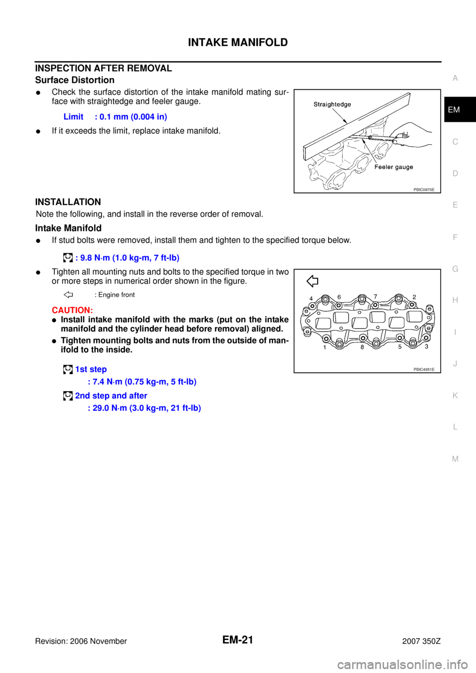
INSPECTION AFTER REMOVAL
Surface Distortion
�Check the surface distortion of the intake manifold mating sur-
face with straightedge and feeler gauge.
�If it exceeds the limit, replace intake manifold.
INSTALLATION
Note the following, and install in the reverse order of removal.
Intake Manifold
�If stud bolts were removed, install them and tighten to the specified torque below.
�Tighten all mounting nuts and bolts to the specified torque in two
or more steps in numerical order shown in the figure.
CAUTION:
�Install intake manifold with the marks (put on the intake
manifold and the cylinder head before removal) aligned.
�Tighten mounting bolts and nuts from the outside of man-
ifold to the inside.Limit : 0.1 mm (0.004 in)
PBIC0870E
: 9.8 N·m (1.0 kg-m, 7 ft-lb)
: Engine front
1st step
: 7.4 N·m (0.75 kg-m, 5 ft-lb)
2nd step and after
: 29.0 N·m (3.0 kg-m, 21 ft-lb)PBIC4951E
Page 22 of 148

EM-22
EXHAUST MANIFOLD AND THREE WAY CATALYST
Revision: 2006 November2007 350Z
EXHAUST MANIFOLD AND THREE WAY CATALYSTPFP:14004
Removal and InstallationNBS0000K
�Refer to GI-11, "Components" for symbol marks in the figure.
REMOVAL
WARNING:
Perform the work when the exhaust and cooling system have completely cooled down.
NOTE:
When removing right bank side parts only, step 3, 10 and 11 are unnecessary.
1. Remove tower bar. Refer to FSU-20, "
TOWER BAR" .
2. Remove engine cover with power tool. Refer to EM-17, "
INTAKE MANIFOLD COLLECTOR" .
3. Drain engine coolant. Refer to CO-10, "
Changing Engine Coolant" .
CAUTION:
�Perform this step when engine is cold.
�Do not spill engine coolant on drive belts.
4. Remove air cleaner case and air duct. Refer to EM-15, "
AIR CLEANER AND AIR DUCT" .
1. Heated oxygen sensor (bank 1) 2. Air fuel ratio sensor (bank 1) 3.Exhaust manifold cover
(upper)
4. Exhaust manifold (right bank) 5. Exhaust manifold cover (lower) 6. Gasket
7. Ring gasket 8. Three way catalyst (right bank) 9. Gasket
10. Heated oxygen sensor (bank 2) 11. Gasket 12. Three way catalyst (left bank)
13. Ring gasket 14. Exhaust manifold (left bank) 15. Exhaust manifold cover (lower)
16. Gasket 17. Air fuel ratio sensor (bank 2) 18.Exhaust manifold cover
(upper)
PBIC4952E
Page 23 of 148

EXHAUST MANIFOLD AND THREE WAY CATALYST
EM-23
C
D
E
F
G
H
I
J
K
L
MA
EM
Revision: 2006 November2007 350Z
5. Remove undercover with power tool.
6. Disconnect heated oxygen sensor harness connectors.
CAUTION:
�Be careful not to damage heated oxygen sensor 2.
�Discard any heated oxygen sensor 2 which has been dropped onto a hard surface such as a
concrete floor. Replace with a new sensor.
7. Remove exhaust mounting bracket between three way catalysts (right and left bank) and transmission.
Refer to EX-3, "
EXHAUST SYSTEM" .
8. Remove exhaust front tube and three way catalysts (right and left bank).
9. Disconnect harness connector and remove air fuel ratio sensor
1 on both banks using heated oxygen sensor wrench (SST).
�Put marks to identify installation positions of each air fuel ratio
sensor 1.
CAUTION:
�Be careful not to damage air fuel ratio sensor 1.
�Discard any air fuel ratio sensor 1 which has been
dropped onto a hard surface such as a concrete floor.
Replace with a new sensor.
10. Disconnect steering lower joint at power steering gear assembly side, and release steering lower shaft.
Refer to PS-17, "
POWER STEERING GEAR AND LINKAGE"
11. Remove water bypass pipe and heater pipe. Refer to CO-28, "WATER OUTLET AND WATER PIPING" .
12. Remove exhaust manifold cover.
13. Loosen mounting nuts in reverse order as shown in the figure to
remove exhaust manifold.
NOTE:
Disregard the numerical order No. 7 and 8 in removal.
14. Remove gaskets.
CAUTION:
Cover engine openings to avoid entry of foreign materials.
PBIC2299E
A : Right bank
B : Left bank
: Engine front
PBIC4953E
Page 24 of 148

EM-24
EXHAUST MANIFOLD AND THREE WAY CATALYST
Revision: 2006 November2007 350Z
INSPECTION AFTER REMOVAL
Surface Distortion
�Check the surface distortion of the exhaust manifold mating sur-
face with straightedge and feeler gauge.
�If it exceeds the limit, replace exhaust manifold.
INSTALLATION
Note the following, and install in the reverse order of removal.
Exhaust Manifold Gasket
�Install exhaust manifold gasket in direction shown in the figure.
Exhaust Manifold
�If stud bolts were removed, install them and tighten to the specified torque below.
�Install mounting exhaust manifold in numerical order as shown
in the figure.
NOTE:
Tighten nuts No. 1 and 2 in two steps. The numerical order No. 7
and 8 shown second step.
Air Fuel Ratio Sensor 1 and Heated Oxygen Sensor 2
�Install air fuel ratio sensor 1 and heated oxygen sensor 2 in the original position.Limit : 0.7 mm (0.028 in)
PBIC1096E
A : Right bank
B : Triangle press
C : Left bank
: Engine front
PBIC4954E
: 14.7 N·m (1.5 kg-m, 11 ft-lb)
A : Right bank
B : Left bank
: Engine front
PBIC4953E
 1
1 2
2 3
3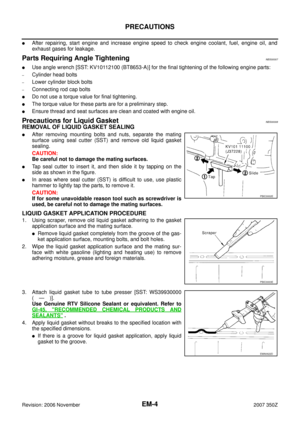 4
4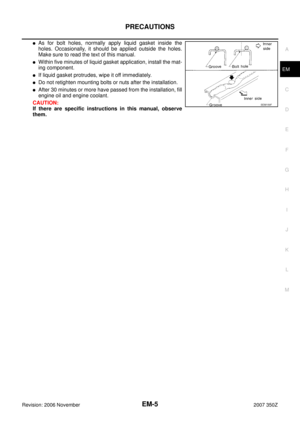 5
5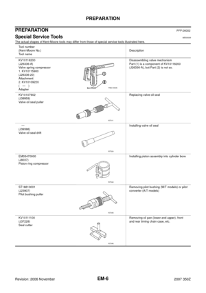 6
6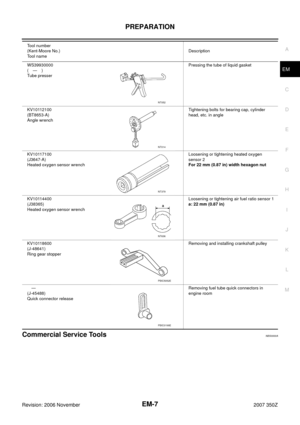 7
7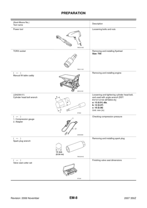 8
8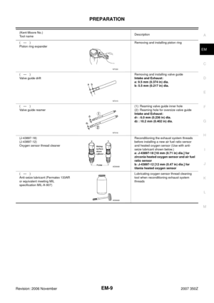 9
9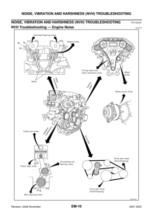 10
10 11
11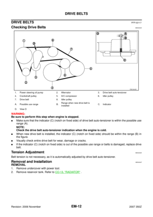 12
12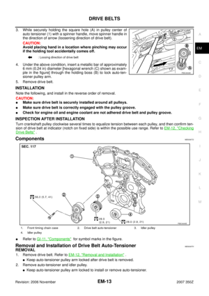 13
13 14
14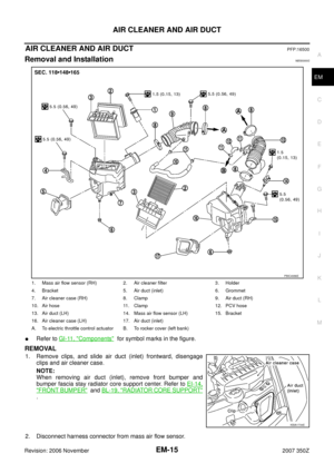 15
15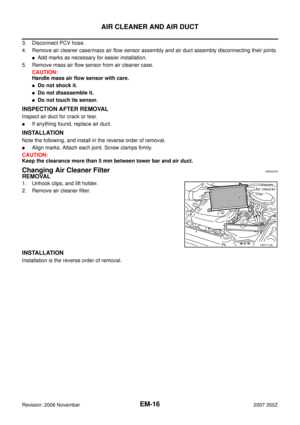 16
16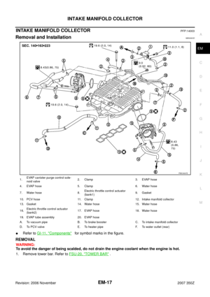 17
17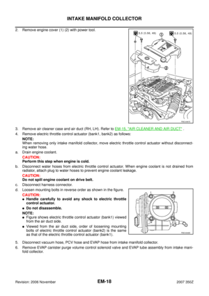 18
18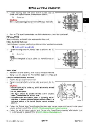 19
19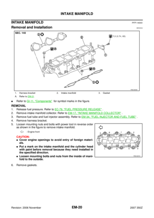 20
20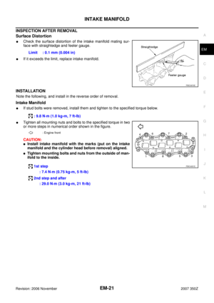 21
21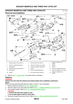 22
22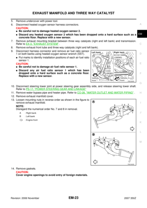 23
23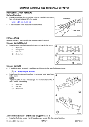 24
24 25
25 26
26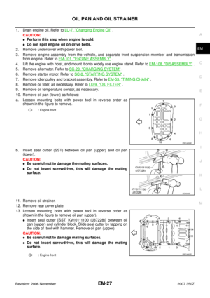 27
27 28
28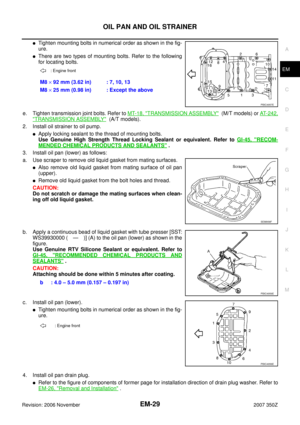 29
29 30
30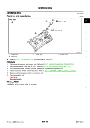 31
31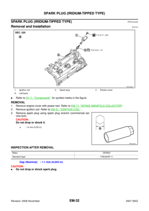 32
32 33
33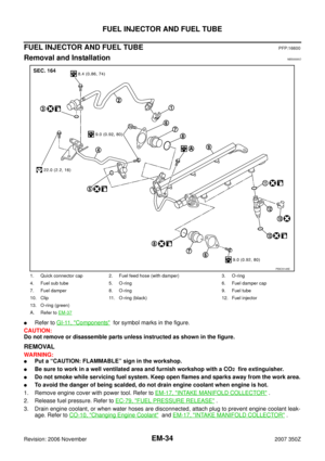 34
34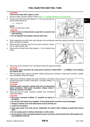 35
35 36
36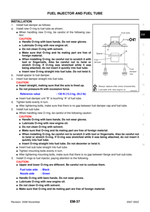 37
37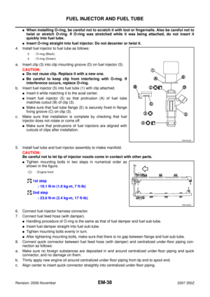 38
38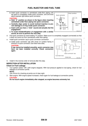 39
39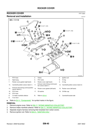 40
40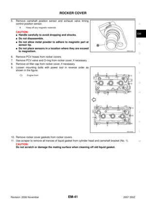 41
41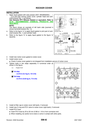 42
42 43
43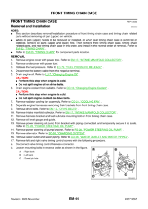 44
44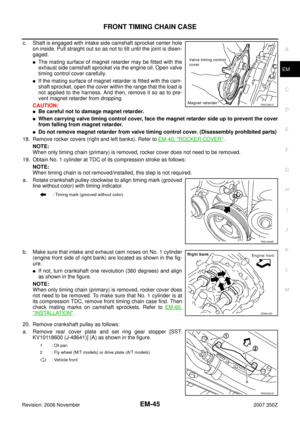 45
45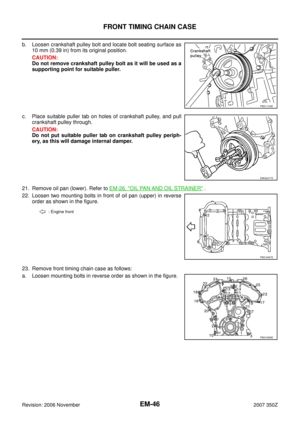 46
46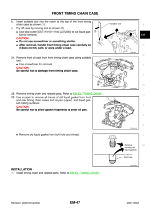 47
47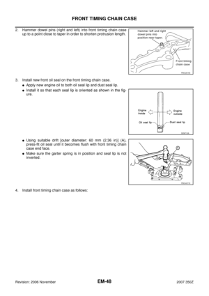 48
48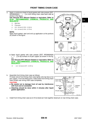 49
49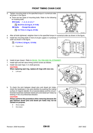 50
50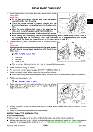 51
51 52
52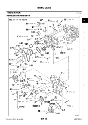 53
53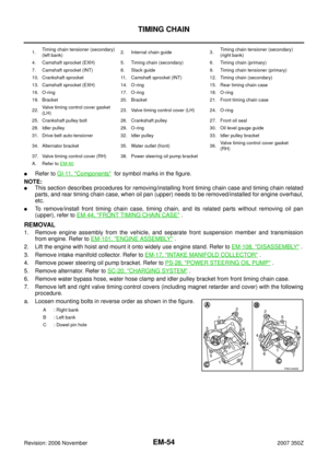 54
54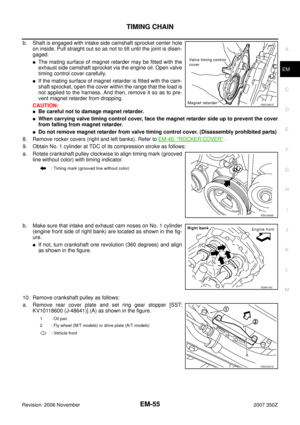 55
55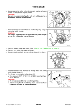 56
56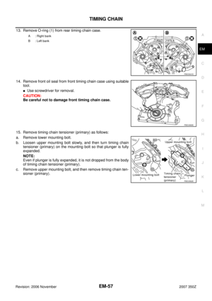 57
57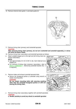 58
58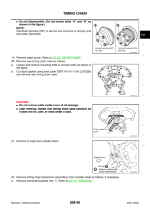 59
59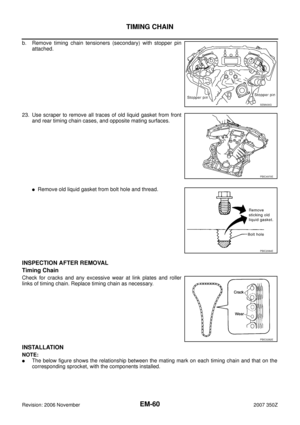 60
60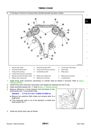 61
61 62
62 63
63 64
64 65
65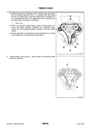 66
66 67
67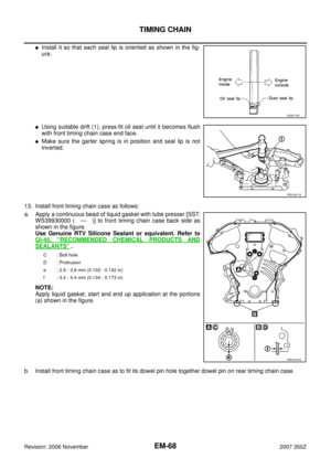 68
68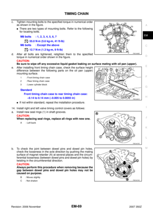 69
69 70
70 71
71 72
72 73
73 74
74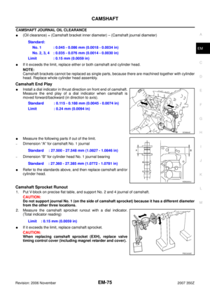 75
75 76
76 77
77 78
78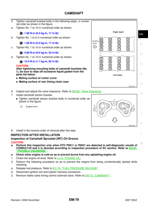 79
79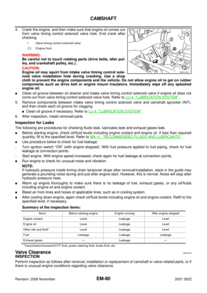 80
80 81
81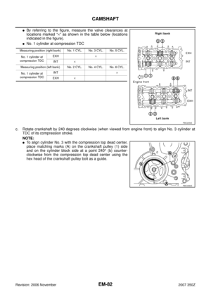 82
82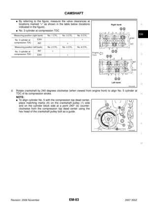 83
83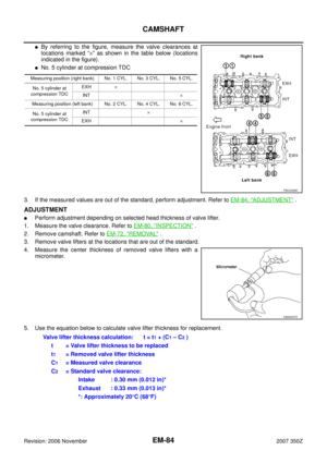 84
84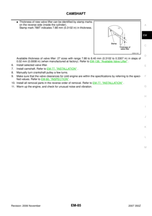 85
85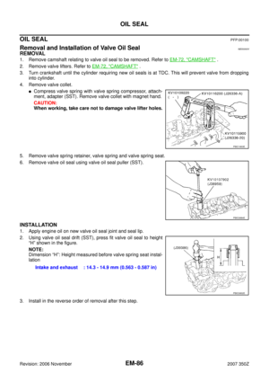 86
86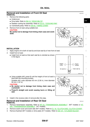 87
87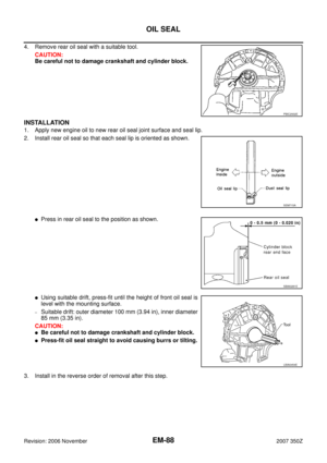 88
88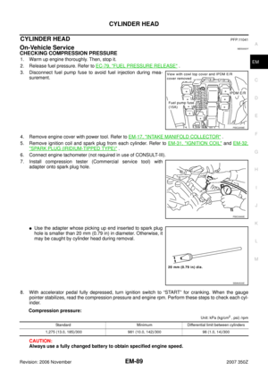 89
89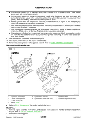 90
90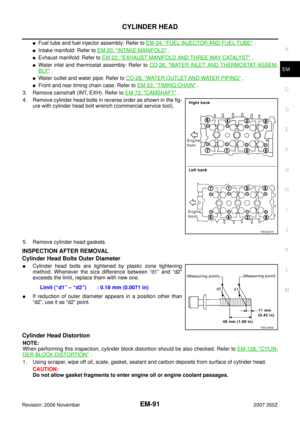 91
91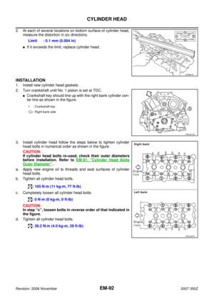 92
92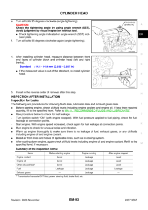 93
93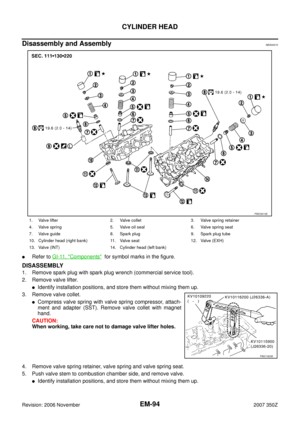 94
94 95
95 96
96 97
97 98
98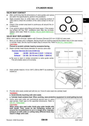 99
99 100
100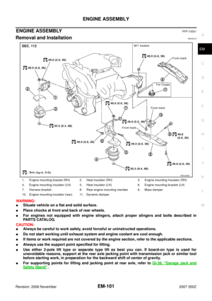 101
101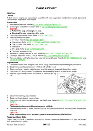 102
102 103
103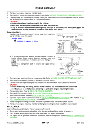 104
104 105
105 106
106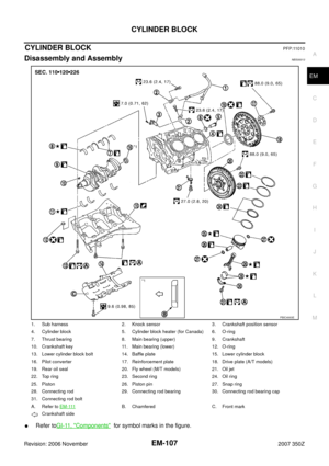 107
107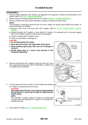 108
108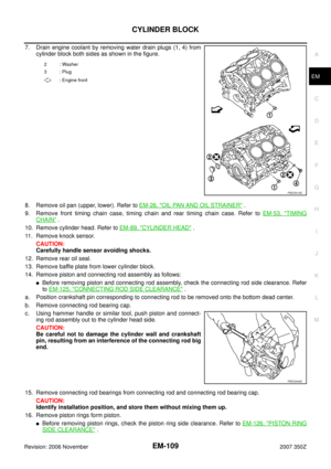 109
109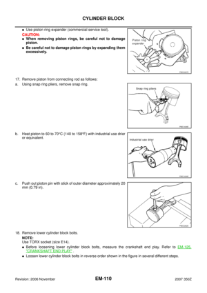 110
110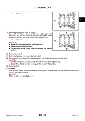 111
111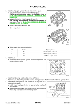 112
112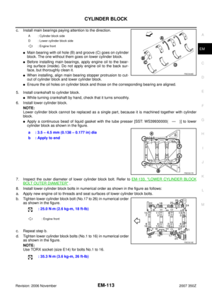 113
113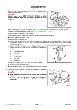 114
114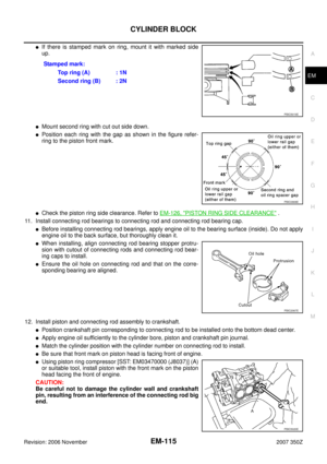 115
115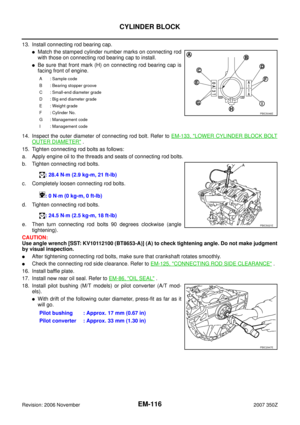 116
116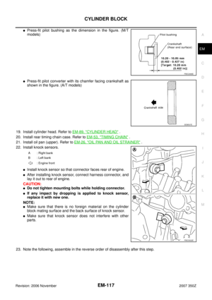 117
117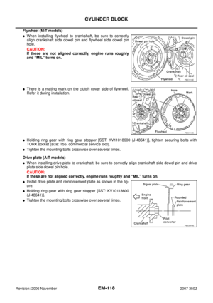 118
118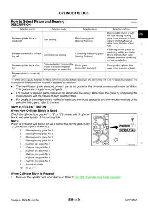 119
119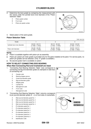 120
120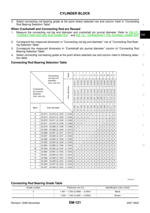 121
121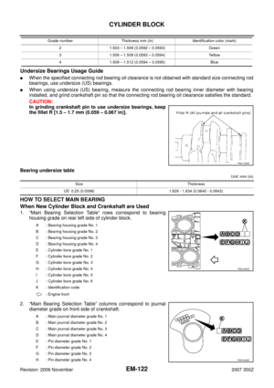 122
122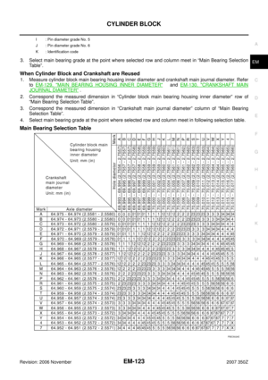 123
123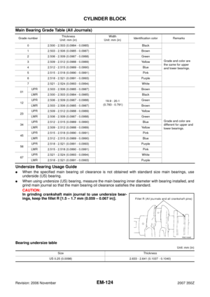 124
124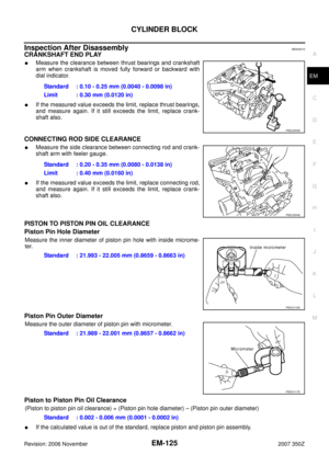 125
125 126
126 127
127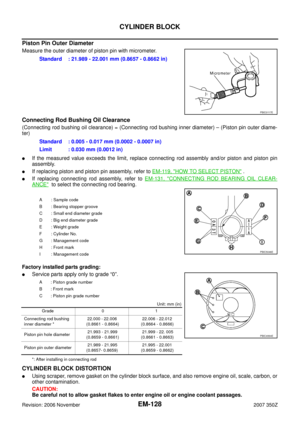 128
128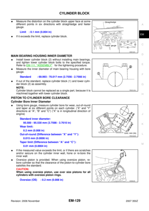 129
129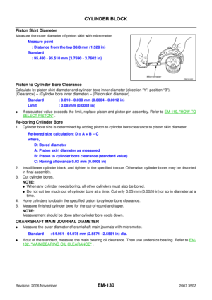 130
130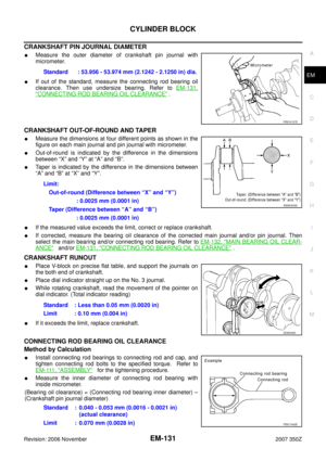 131
131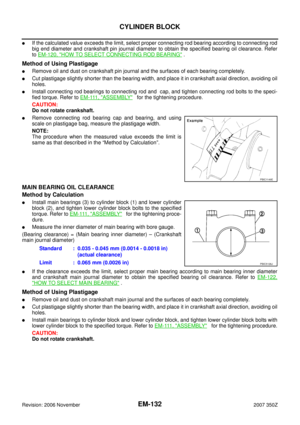 132
132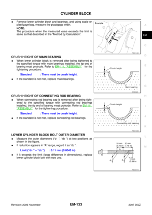 133
133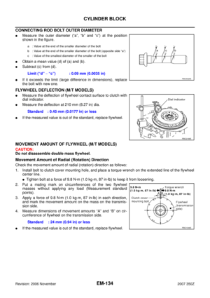 134
134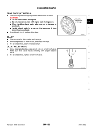 135
135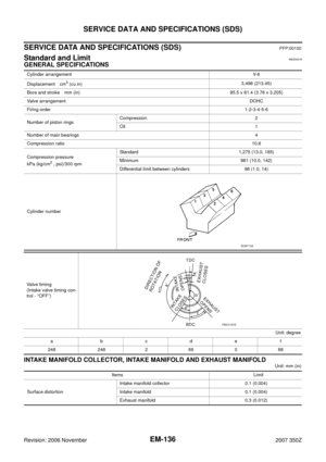 136
136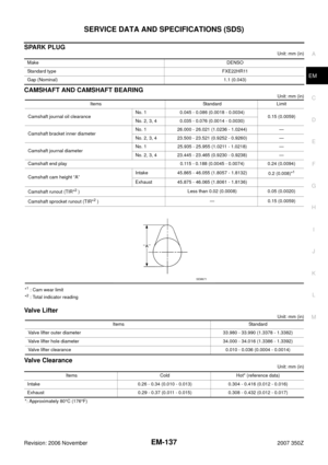 137
137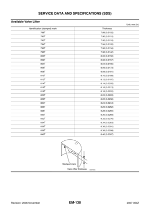 138
138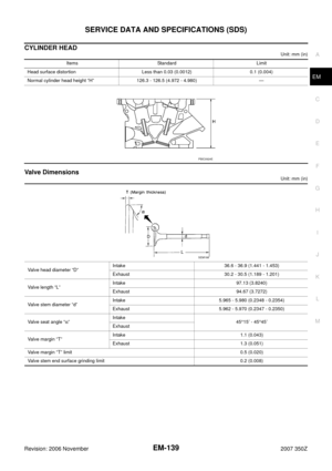 139
139 140
140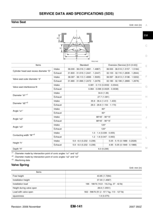 141
141 142
142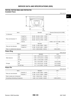 143
143 144
144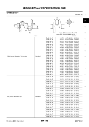 145
145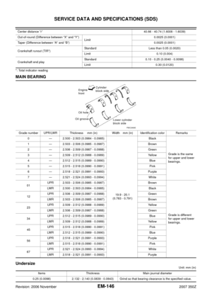 146
146 147
147