Page 65 of 148
TIMING CHAIN
EM-65
C
D
E
F
G
H
I
J
K
L
MA
EM
Revision: 2006 November2007 350Z
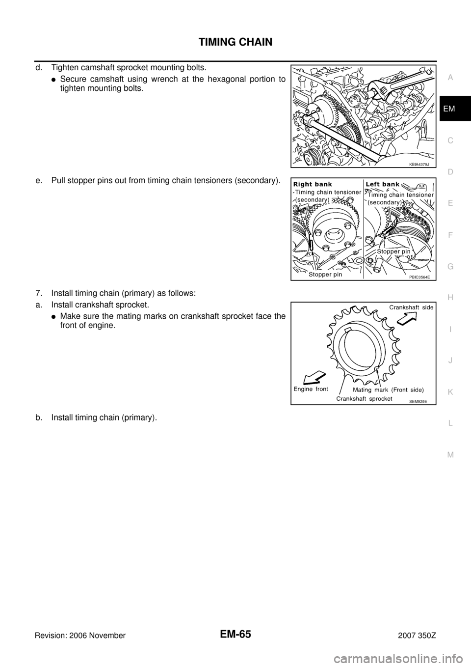
d. Tighten camshaft sprocket mounting bolts.
�Secure camshaft using wrench at the hexagonal portion to
tighten mounting bolts.
e. Pull stopper pins out from timing chain tensioners (secondary).
7. Install timing chain (primary) as follows:
a. Install crankshaft sprocket.
�Make sure the mating marks on crankshaft sprocket face the
front of engine.
b. Install timing chain (primary).
KBIA4379J
PBIC3564E
SEM929E
Page 66 of 148
EM-66
TIMING CHAIN
Revision: 2006 November2007 350Z
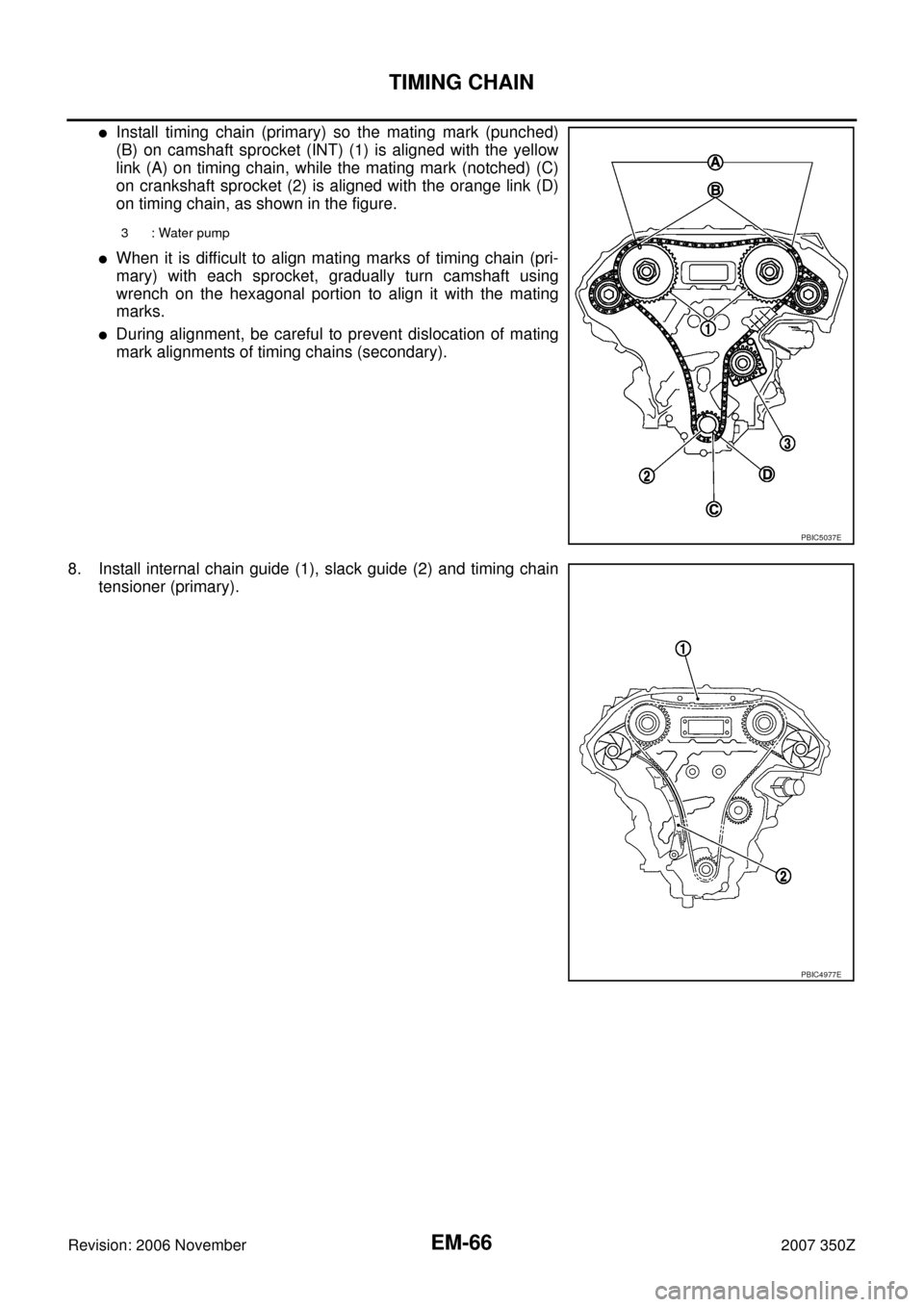
�Install timing chain (primary) so the mating mark (punched)
(B) on camshaft sprocket (INT) (1) is aligned with the yellow
link (A) on timing chain, while the mating mark (notched) (C)
on crankshaft sprocket (2) is aligned with the orange link (D)
on timing chain, as shown in the figure.
�When it is difficult to align mating marks of timing chain (pri-
mary) with each sprocket, gradually turn camshaft using
wrench on the hexagonal portion to align it with the mating
marks.
�During alignment, be careful to prevent dislocation of mating
mark alignments of timing chains (secondary).
8. Install internal chain guide (1), slack guide (2) and timing chain
tensioner (primary).
3 : Water pump
PBIC5037E
PBIC4977E
Page 67 of 148

TIMING CHAIN
EM-67
C
D
E
F
G
H
I
J
K
L
MA
EM
Revision: 2006 November2007 350Z
CAUTION:
Do not overtighten slack guide mounting bolts. It is normal
for a gap to exist under the bolt seats when mounting bolts
are tightened to specification.
9. Install the timing chain tensioner (primary) with the following procedure:
a. Pull plunger stopper tab up (or turn lever downward) so as to
remove plunger stopper tab from the ratchet of plunger.
NOTE:
Plunger stopper tab and lever are synchronized.
b. Push plunger into the inside of tensioner body.
c. Hold plunger in the fully compressed position by engaging
plunger stopper tab with the tip of ratchet.
d. To secure lever, insert stopper pin through hole of lever into ten-
sioner body hole.
�The lever parts and the tab are synchronized. Therefore, the
plunger will be secured under this condition.
NOTE:
Figure shows the example of 1.2 mm (0.047 in) diameter thin screwdriver being used as the stopper pin.
e. Install timing chain tensioner (primary).
�Remove any dirt and foreign materials completely from the
back and the mounting surfaces of timing chain tensioner (pri-
mary).
f. Pull out stopper pin after installing, and then release plunger.
10. Make sure again that the mating marks on sprockets and timing chain have not slipped out of alignment.
11. Install new O-ring (1) on rear timing chain case.
12. Install new front oil seal on front timing chain case.
�Apply new engine oil to both oil seal lip and dust seal lip.
PBIC2633E
PBIC3568E
PBIC3569E
A : Right bank
B : Left bank
PBIC5041E
Page 68 of 148
EM-68
TIMING CHAIN
Revision: 2006 November2007 350Z
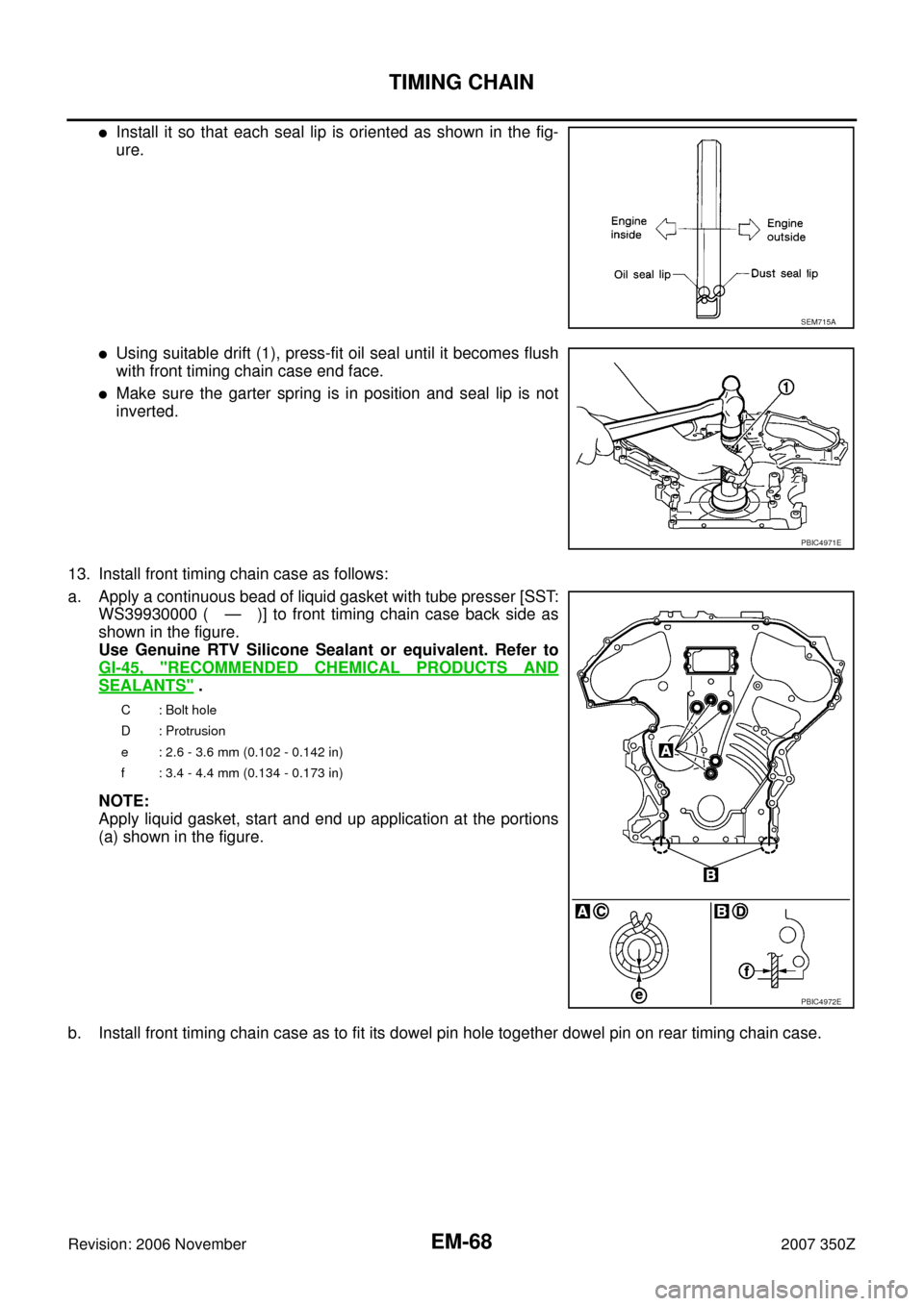
�Install it so that each seal lip is oriented as shown in the fig-
ure.
�Using suitable drift (1), press-fit oil seal until it becomes flush
with front timing chain case end face.
�Make sure the garter spring is in position and seal lip is not
inverted.
13. Install front timing chain case as follows:
a. Apply a continuous bead of liquid gasket with tube presser [SST:
WS39930000 ( — )] to front timing chain case back side as
shown in the figure.
Use Genuine RTV Silicone Sealant or equivalent. Refer to
GI-45, "
RECOMMENDED CHEMICAL PRODUCTS AND
SEALANTS" .
NOTE:
Apply liquid gasket, start and end up application at the portions
(a) shown in the figure.
b. Install front timing chain case as to fit its dowel pin hole together dowel pin on rear timing chain case.
SEM715A
PBIC4971E
C: Bolt hole
D : Protrusion
e : 2.6 - 3.6 mm (0.102 - 0.142 in)
f : 3.4 - 4.4 mm (0.134 - 0.173 in)
PBIC4972E
Page 69 of 148

TIMING CHAIN
EM-69
C
D
E
F
G
H
I
J
K
L
MA
EM
Revision: 2006 November2007 350Z
c. Tighten mounting bolts to the specified torque in numerical order
as shown in the figure.
�There are two types of mounting bolts. Refer to the following
for locating bolts.
d. After all bolts are tightened, retighten them to the specified
torque in numerical order shown in the figure.
CAUTION:
Be sure to wipe off any excessive liquid gasket leaking on surface mating with oil pan (upper).
e. After installing front timing chain case, check the surface height
difference between the following parts on the oil pan (upper)
mounting surface.
�If not within standard, repeat the installation procedure.
14. Install right and left valve timing control covers as follows:
a. Install new seal rings (1) in shaft grooves.
CAUTION:
When replacing seal rings, replace all rings with new one.
b. To check the joint between dowel pins and dowel pin holes,
check the looseness in the axle direction by pushing the mating
surface of magnet retarder (A) at several places and the circum-
ferential looseness (between dowel pins and dowel pin holes) by
twisting in the circumferential direction.
CAUTION:
Always perform this procedure when removing because the
gap between dowel pins and dowel pin holes may not be
caused on purpose.M8 bolts : 1, 2, 3, 4, 5, 6, 7
: 55.0 N·m (5.6 kg-m, 41 ft-lb)
M6 bolts : Except the above
: 12.7 N·m (1.3 kg-m, 9 ft-lb)
1 : Front timing chain case
2 : Rear timing chain case
3 : Lower cylinder block
Standard
Front timing chain case to rear timing chain case:
–0.14 to 0.14 mm (–0.005 to 0.0055 in)
PBIC4968E
PBIC4981E
A : Left bank
PBIC4973E
B : Moves slightly
C : Not shaken
PBIC4974E
Page 70 of 148

EM-70
TIMING CHAIN
Revision: 2006 November2007 350Z
c. Install valve timing control cover to front timing chain case.
CAUTION:
�Do not face the magnet retarder side down to prevent
magnet retarder from dropping.
�Check the mating surface of magnet retarder and the
drum of exhaust side camshaft sprocket for foreign mate-
rials.
�Align the center of both shaft holes of the shaft and the
intake side camshaft sprocket, and then insert them.
�Be careful not to drop the seal ring from the shaft groove.
�When setting the valve timing control cover in position
by hand, if valve timing control cover is not contacting with the front timing chain case, the
dowel pin of magnet retarder may not be aligned with the dowel pin holes of cover. In this case,
return to step “b”.
d. Tighten mounting bolts in numerical order as shown in the fig-
ure.
CAUTION:
Completely tighten the mounting bolts with the seat surface
of valve timing control cover contacting with front timing
chain case.
�After all bolts are tightened, tighten No.1 bolt to the specified torque again.
15. Install oil pans (upper and lower). Refer to EM-26, "
OIL PAN AND OIL STRAINER" .
16. Install rocker covers (right and left banks). Refer to EM-40, "
ROCKER COVER" .
17. Install crankshaft pulley as follows:
a. Fix crankshaft using ring gear stopper [SST: KV10118600 (J-48641)].
b. Install crankshaft pulley, taking care not to damage front oil seal.
�When press-fitting crankshaft pulley with plastic hammer, tap on its center portion (not circumference).
c. Tighten crankshaft pulley bolt.
d. Place a paint mark (A) on crankshaft pulley (2) aligning with the
angle mark (C) on crankshaft pulley bolt (1). Tighten the bolt 90
degrees (one marks) (b).
18. Rotate crankshaft pulley in normal direction (clockwise when viewed from engine front) to confirm it turns
smoothly.
19. Install in the reverse order of removal after this step.: 11.3 N·m (1.2 kg-m, 8 ft-lb)
A : Right bank
B : Left bank
C : Dowel pin hole
: 44.1 N·m (4.5 kg-m, 33 ft-lb)
PBIC3561E
PBIC4965E
PBIC4975E
Page 71 of 148

TIMING CHAIN
EM-71
C
D
E
F
G
H
I
J
K
L
MA
EM
Revision: 2006 November2007 350Z
INSPECTION AFTER INSTALLATION
Inspection for Leaks
The following are procedures for checking fluids leak, lubricates leak and exhaust gases leak.
�Before starting engine, check oil/fluid levels including engine coolant and engine oil. If less than required
quantity, fill to the specified level. Refer to MA-11, "
RECOMMENDED FLUIDS AND LUBRICANTS" .
�Use procedure below to check for fuel leakage.
–Turn ignition switch “ON” (with engine stopped). With fuel pressure applied to fuel piping, check for fuel
leakage at connection points.
–Start engine. With engine speed increased, check again for fuel leakage at connection points.
�Run engine to check for unusual noise and vibration.
NOTE:
If hydraulic pressure inside timing chain tensioner drops after removal/installation, slack in the guide may
generate a pounding noise during and just after engine start. However, this is normal. Noise will stop after
hydraulic pressure rises.
�Warm up engine thoroughly to make sure there is no leakage of fuel, exhaust gases, or any oil/fluids
including engine oil and engine coolant.
�Bleed air from lines and hoses of applicable lines, such as in cooling system.
�After cooling down engine, again check oil/fluid levels including engine oil and engine coolant. Refill to the
specified level, if necessary.
Summary of the inspection items:
* Transmission/transaxle/CVT fluid, power steering fluid, brake fluid, etc.Items Before starting engine Engine running After engine stopped
Engine coolant Level Leakage Level
Engine oil Level Leakage Level
Other oils and fluid* Level Leakage Level
Fuel Leakage Leakage Leakage
Exhaust gases — Leakage —
Page 72 of 148

EM-72
CAMSHAFT
Revision: 2006 November2007 350Z
CAMSHAFTPFP:13001
Removal and InstallationNBS0000T
�Refer to GI-11, "Components" for symbol marks in the figure.
REMOVAL
1. Remove front timing chain case, camshaft sprocket, and timing chain. Refer to EM-53, "TIMING CHAIN" .
1. Camshaft bracket (No. 3, 4) 2. Camshaft bracket (No. 2) 3. Seal washer
4. Camshaft bracket (No. 1) 5. Dowel pin 6. Camshaft (EXH) (right bank)
7. Camshaft signal plate (EXH) 8. Camshaft sensor bracket 9. Dowel pin
10. Camshaft signal plate (INT) 11. Camshaft (INT) (right bank) 12. Valve lifter
13. Cylinder head (right bank) 14. Plunger 15. Spring
16.Timing chain tensioner (secondary)
(right bank)17. Camshaft bracket (No. 3, 4) 18. Camshaft bracket (No. 2)
19. Camshaft bracket (No. 1) 20. Camshaft signal plate (INT) 21. Camshaft signal plate (EXH)
22. Camshaft sensor bracket 23. Cylinder head (left bank) 24.Timing chain tensioner (secondary)
(left bank)
25. Camshaft (EXH) (left bank) 26. Camshaft (INT) (left bank)
A. Refer to EM-77
PBIC4983E
 1
1 2
2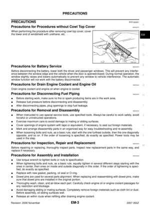 3
3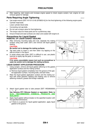 4
4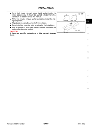 5
5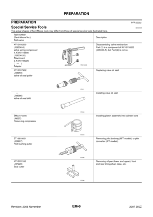 6
6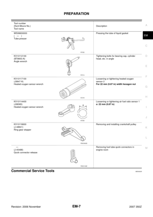 7
7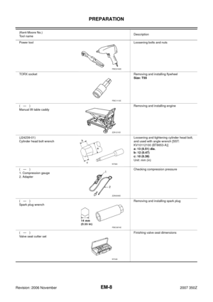 8
8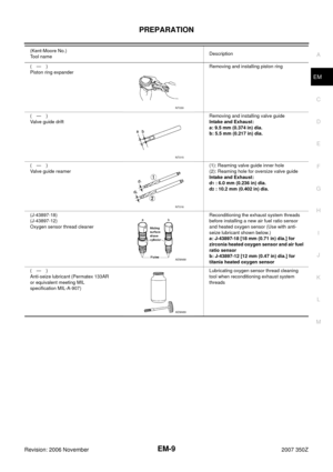 9
9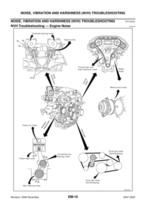 10
10 11
11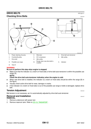 12
12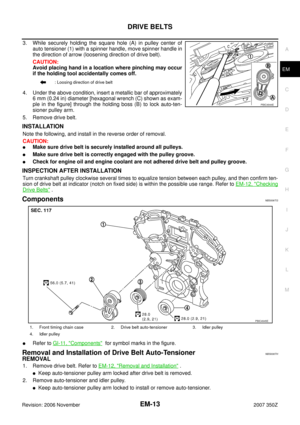 13
13 14
14 15
15 16
16 17
17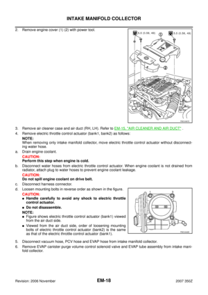 18
18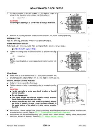 19
19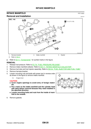 20
20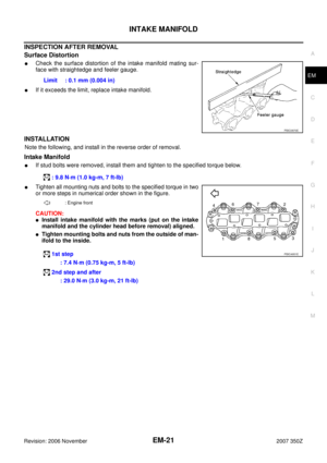 21
21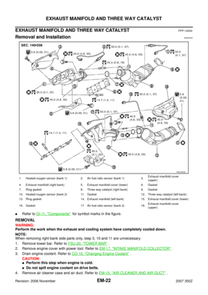 22
22 23
23 24
24 25
25 26
26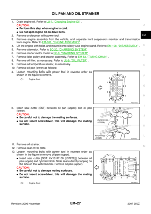 27
27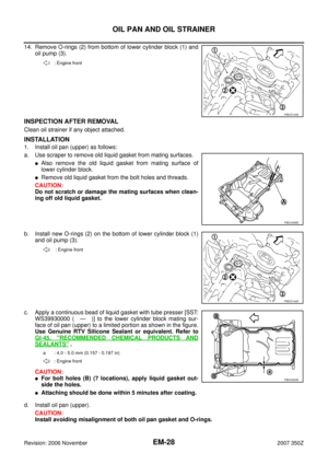 28
28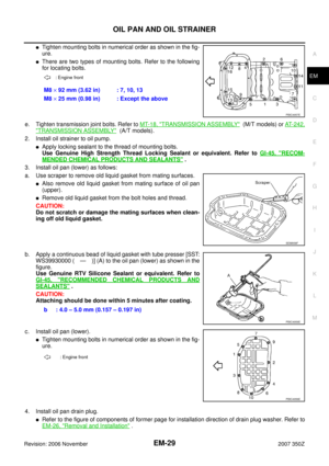 29
29 30
30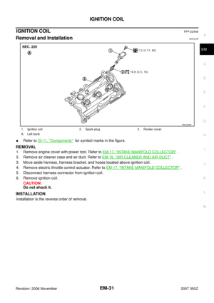 31
31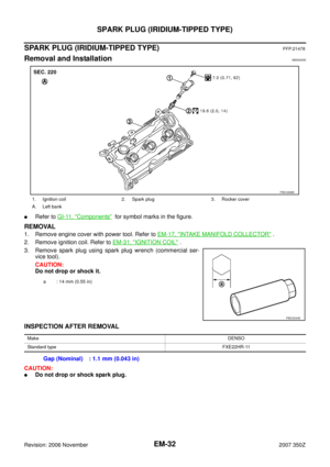 32
32 33
33 34
34 35
35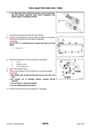 36
36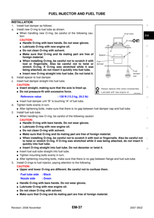 37
37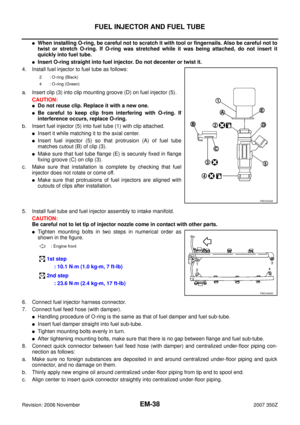 38
38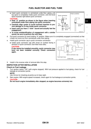 39
39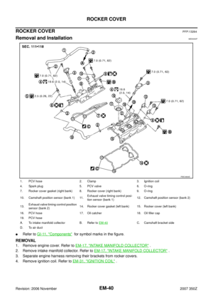 40
40 41
41 42
42 43
43 44
44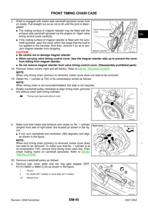 45
45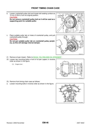 46
46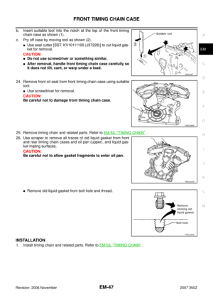 47
47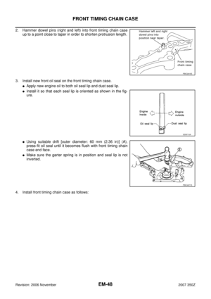 48
48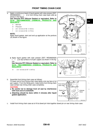 49
49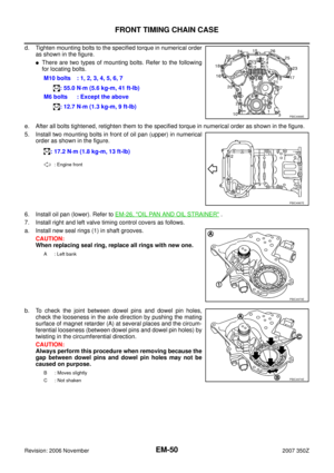 50
50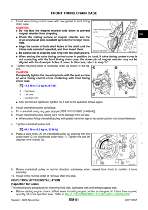 51
51 52
52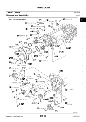 53
53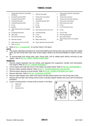 54
54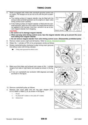 55
55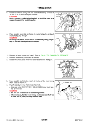 56
56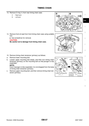 57
57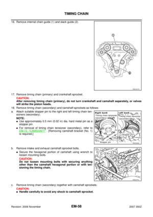 58
58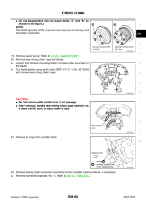 59
59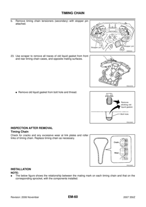 60
60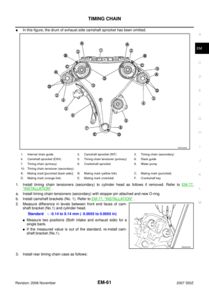 61
61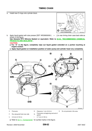 62
62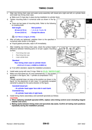 63
63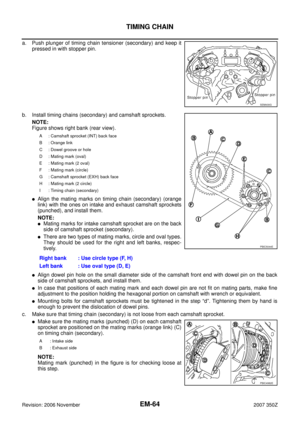 64
64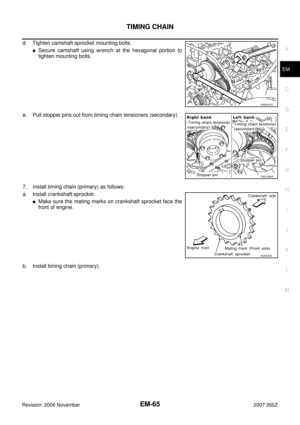 65
65 66
66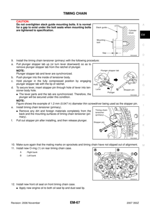 67
67 68
68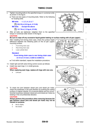 69
69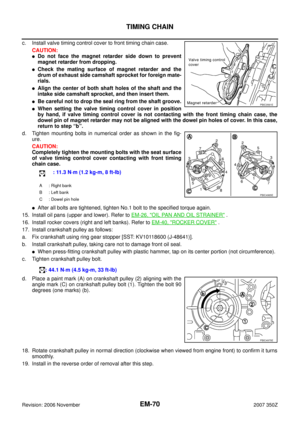 70
70 71
71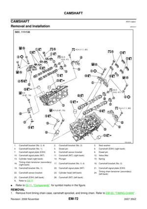 72
72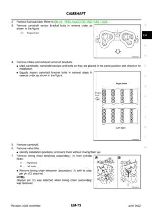 73
73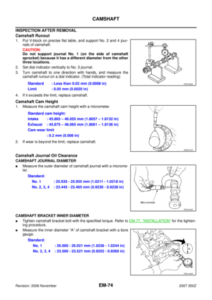 74
74 75
75 76
76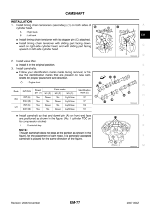 77
77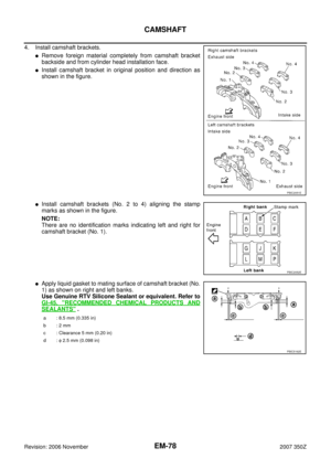 78
78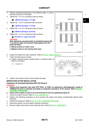 79
79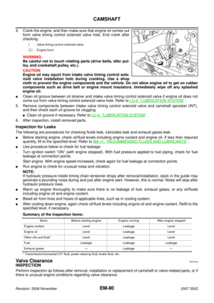 80
80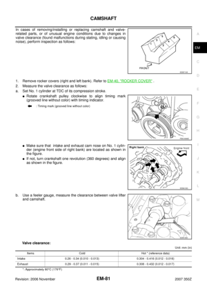 81
81 82
82 83
83 84
84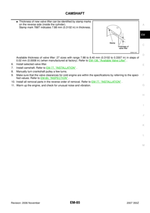 85
85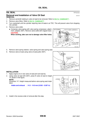 86
86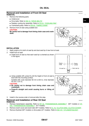 87
87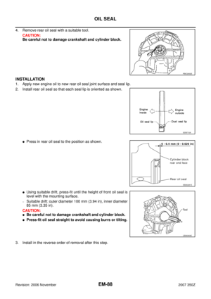 88
88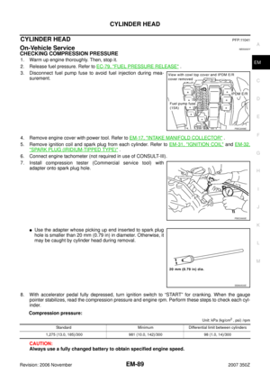 89
89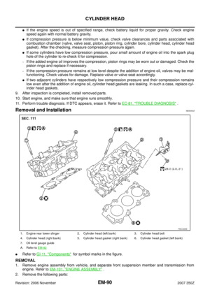 90
90 91
91 92
92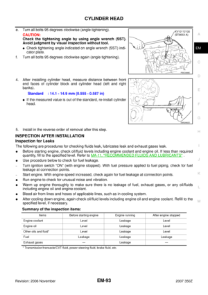 93
93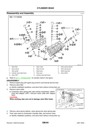 94
94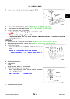 95
95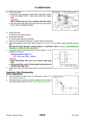 96
96 97
97 98
98 99
99 100
100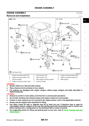 101
101 102
102 103
103 104
104 105
105 106
106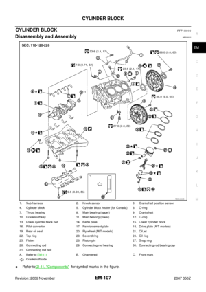 107
107 108
108 109
109 110
110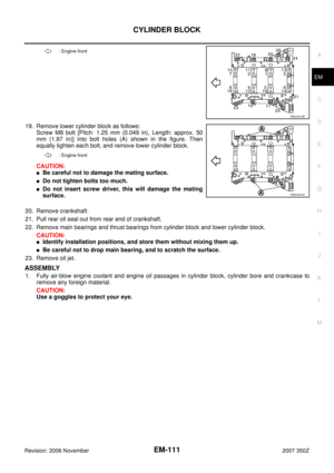 111
111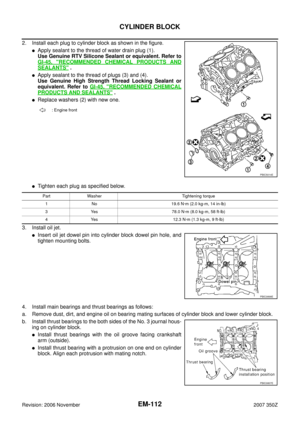 112
112 113
113 114
114 115
115 116
116 117
117 118
118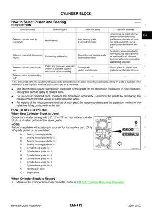 119
119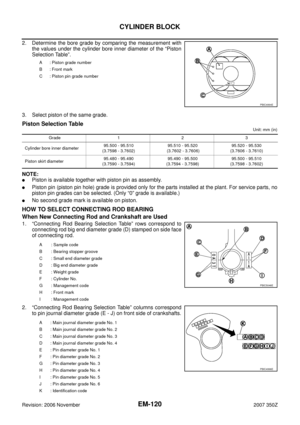 120
120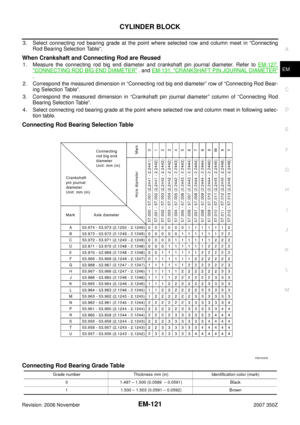 121
121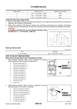 122
122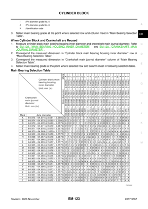 123
123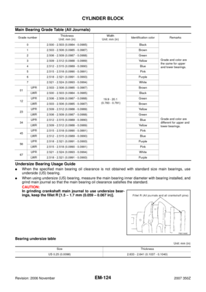 124
124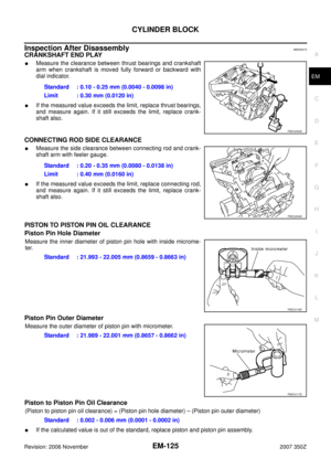 125
125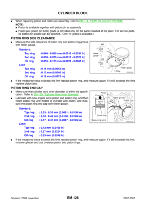 126
126 127
127 128
128 129
129 130
130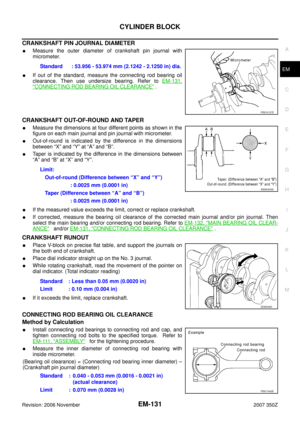 131
131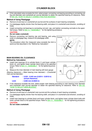 132
132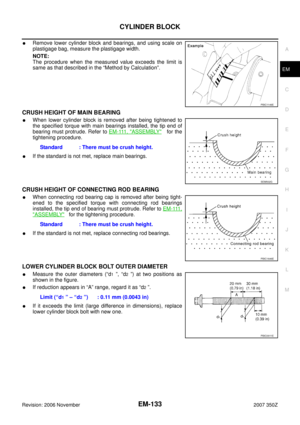 133
133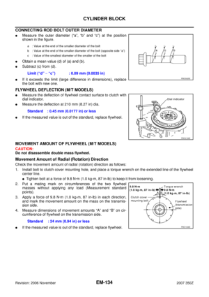 134
134 135
135 136
136 137
137 138
138 139
139 140
140 141
141 142
142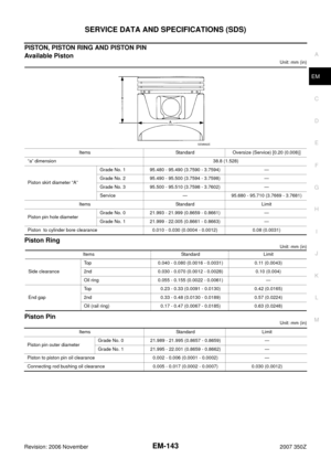 143
143 144
144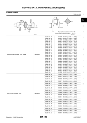 145
145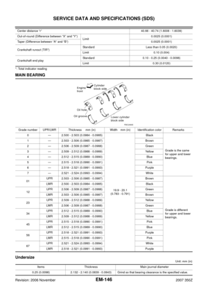 146
146 147
147