Page 74 of 148

EM-74
CAMSHAFT
Revision: 2006 November2007 350Z
INSPECTION AFTER REMOVAL
Camshaft Runout
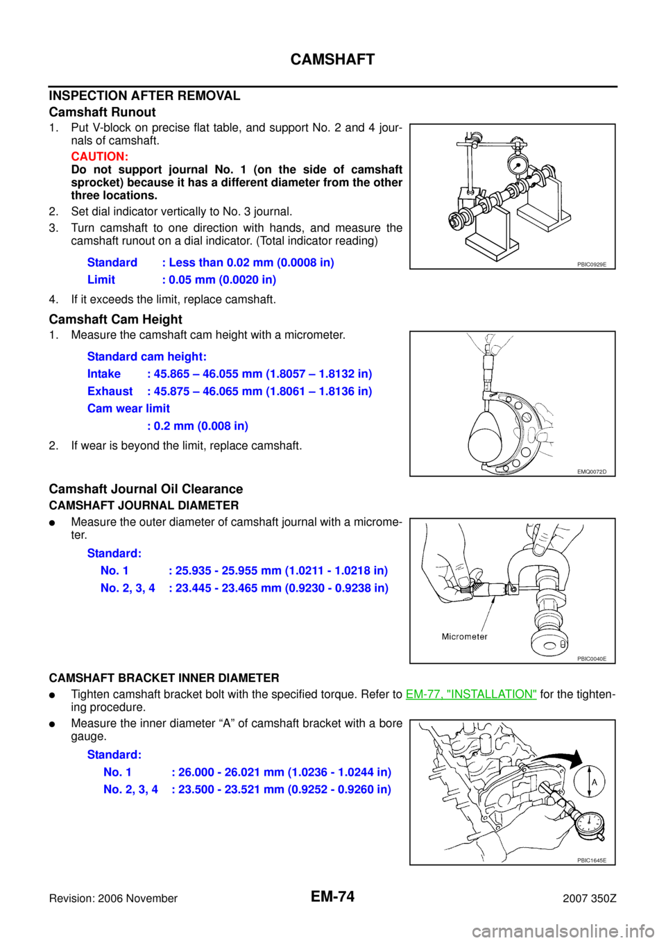
1. Put V-block on precise flat table, and support No. 2 and 4 jour-
nals of camshaft.
CAUTION:
Do not support journal No. 1 (on the side of camshaft
sprocket) because it has a different diameter from the other
three locations.
2. Set dial indicator vertically to No. 3 journal.
3. Turn camshaft to one direction with hands, and measure the
camshaft runout on a dial indicator. (Total indicator reading)
4. If it exceeds the limit, replace camshaft.
Camshaft Cam Height
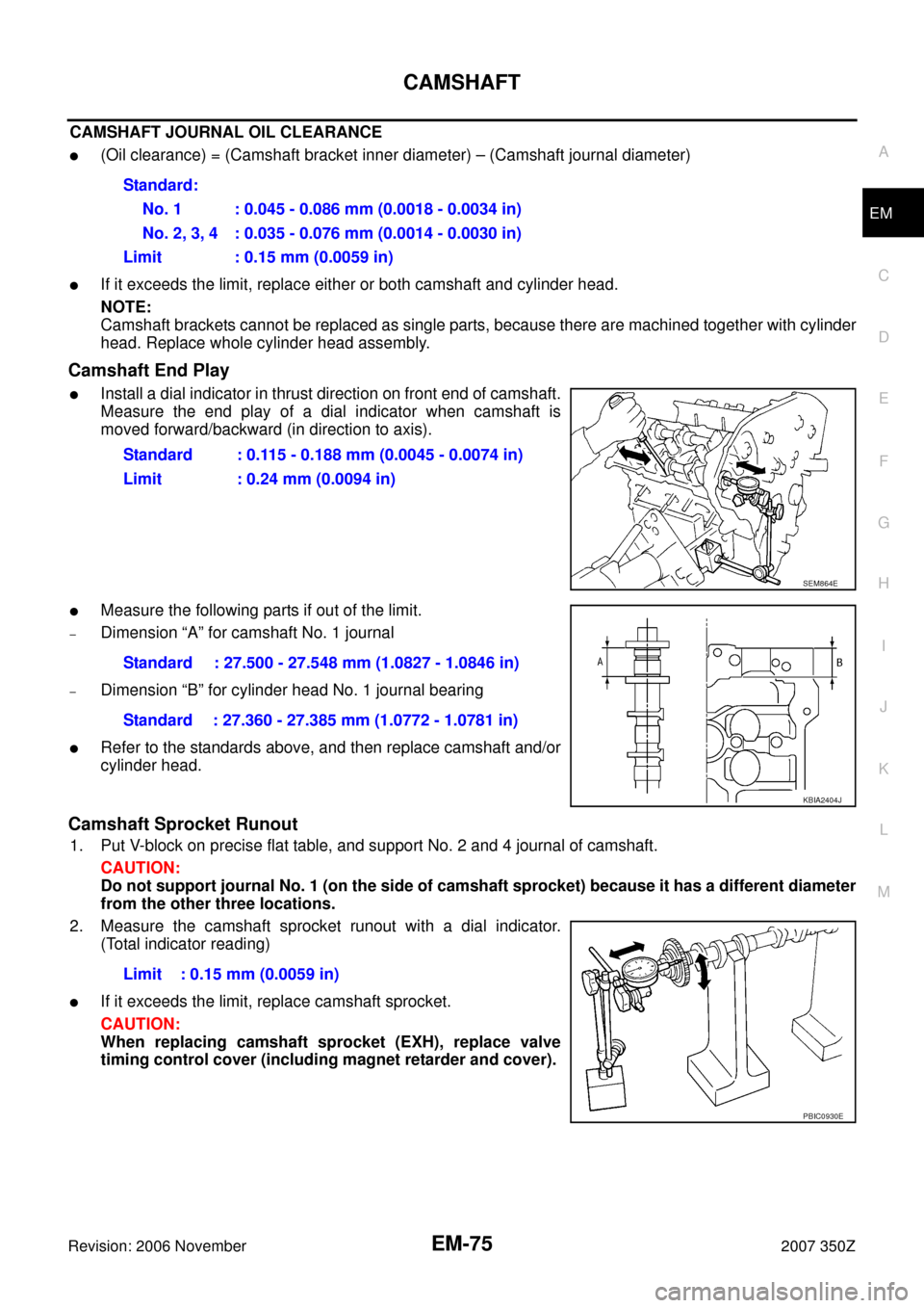
1. Measure the camshaft cam height with a micrometer.
2. If wear is beyond the limit, replace camshaft.
Camshaft Journal Oil Clearance
CAMSHAFT JOURNAL DIAMETER
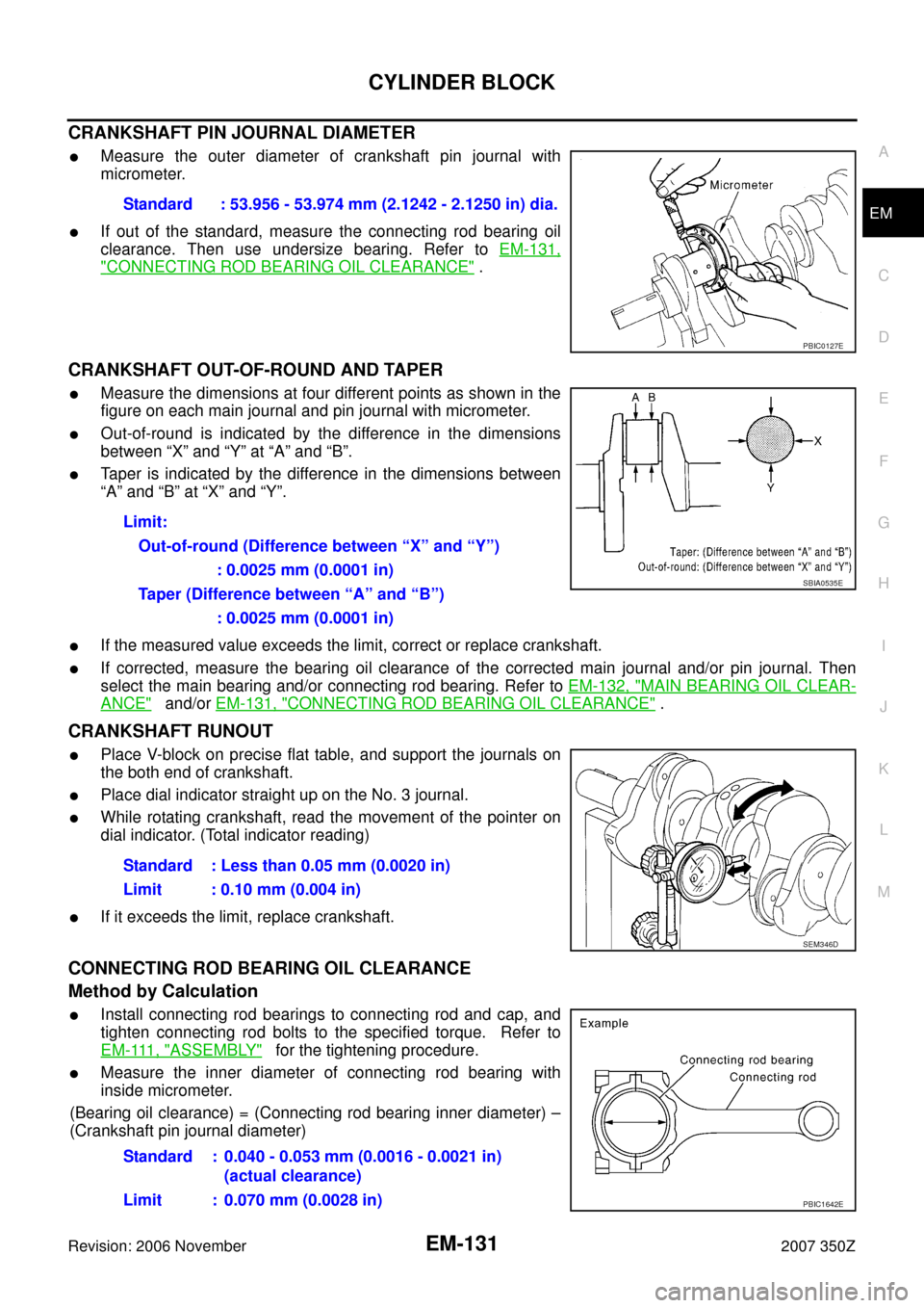
�Measure the outer diameter of camshaft journal with a microme-
ter.
CAMSHAFT BRACKET INNER DIAMETER
�Tighten camshaft bracket bolt with the specified torque. Refer to EM-77, "INSTALLATION" for the tighten-
ing procedure.
�Measure the inner diameter “A” of camshaft bracket with a bore
gauge.Standard : Less than 0.02 mm (0.0008 in)
Limit : 0.05 mm (0.0020 in)
PBIC0929E
Standard cam height:
Intake : 45.865 – 46.055 mm (1.8057 – 1.8132 in)
Exhaust : 45.875 – 46.065 mm (1.8061 – 1.8136 in)
Cam wear limit
: 0.2 mm (0.008 in)
EMQ0072D
Standard:
No. 1 : 25.935 - 25.955 mm (1.0211 - 1.0218 in)
No. 2, 3, 4 : 23.445 - 23.465 mm (0.9230 - 0.9238 in)
PBIC0040E
Standard:
No. 1 : 26.000 - 26.021 mm (1.0236 - 1.0244 in)
No. 2, 3, 4 : 23.500 - 23.521 mm (0.9252 - 0.9260 in)
PBIC1645E
Page 75 of 148

CAMSHAFT
EM-75
C
D
E
F
G
H
I
J
K
L
MA
EM
Revision: 2006 November2007 350Z
CAMSHAFT JOURNAL OIL CLEARANCE
�(Oil clearance) = (Camshaft bracket inner diameter) – (Camshaft journal diameter)
�If it exceeds the limit, replace either or both camshaft and cylinder head.
NOTE:
Camshaft brackets cannot be replaced as single parts, because there are machined together with cylinder
head. Replace whole cylinder head assembly.
Camshaft End Play
�Install a dial indicator in thrust direction on front end of camshaft.
Measure the end play of a dial indicator when camshaft is
moved forward/backward (in direction to axis).
�Measure the following parts if out of the limit.
–Dimension “A” for camshaft No. 1 journal
–Dimension “B” for cylinder head No. 1 journal bearing
�Refer to the standards above, and then replace camshaft and/or
cylinder head.
Camshaft Sprocket Runout
1. Put V-block on precise flat table, and support No. 2 and 4 journal of camshaft.
CAUTION:
Do not support journal No. 1 (on the side of camshaft sprocket) because it has a different diameter
from the other three locations.
2. Measure the camshaft sprocket runout with a dial indicator.
(Total indicator reading)
�If it exceeds the limit, replace camshaft sprocket.
CAUTION:
When replacing camshaft sprocket (EXH), replace valve
timing control cover (including magnet retarder and cover). Standard:
No. 1 : 0.045 - 0.086 mm (0.0018 - 0.0034 in)
No. 2, 3, 4 : 0.035 - 0.076 mm (0.0014 - 0.0030 in)
Limit : 0.15 mm (0.0059 in)
Standard : 0.115 - 0.188 mm (0.0045 - 0.0074 in)
Limit : 0.24 mm (0.0094 in)
SEM864E
Standard : 27.500 - 27.548 mm (1.0827 - 1.0846 in)
Standard : 27.360 - 27.385 mm (1.0772 - 1.0781 in)
KBIA2404J
Limit : 0.15 mm (0.0059 in)
PBIC0930E
Page 131 of 148

CYLINDER BLOCK
EM-131
C
D
E
F
G
H
I
J
K
L
MA
EM
Revision: 2006 November2007 350Z
CRANKSHAFT PIN JOURNAL DIAMETER
�Measure the outer diameter of crankshaft pin journal with
micrometer.
�If out of the standard, measure the connecting rod bearing oil
clearance. Then use undersize bearing. Refer to EM-131,
"CONNECTING ROD BEARING OIL CLEARANCE" .
CRANKSHAFT OUT-OF-ROUND AND TAPER
�Measure the dimensions at four different points as shown in the
figure on each main journal and pin journal with micrometer.
�Out-of-round is indicated by the difference in the dimensions
between “X” and “Y” at “A” and “B”.
�Taper is indicated by the difference in the dimensions between
“A” and “B” at “X” and “Y”.
�If the measured value exceeds the limit, correct or replace crankshaft.
�If corrected, measure the bearing oil clearance of the corrected main journal and/or pin journal. Then
select the main bearing and/or connecting rod bearing. Refer to EM-132, "
MAIN BEARING OIL CLEAR-
ANCE" and/or EM-131, "CONNECTING ROD BEARING OIL CLEARANCE" .
CRANKSHAFT RUNOUT
�Place V-block on precise flat table, and support the journals on
the both end of crankshaft.
�Place dial indicator straight up on the No. 3 journal.
�While rotating crankshaft, read the movement of the pointer on
dial indicator. (Total indicator reading)
�If it exceeds the limit, replace crankshaft.
CONNECTING ROD BEARING OIL CLEARANCE
Method by Calculation
�Install connecting rod bearings to connecting rod and cap, and
tighten connecting rod bolts to the specified torque. Refer to
E M - 111 , "
ASSEMBLY" for the tightening procedure.
�Measure the inner diameter of connecting rod bearing with
inside micrometer.
(Bearing oil clearance) = (Connecting rod bearing inner diameter) –
(Crankshaft pin journal diameter)Standard : 53.956 - 53.974 mm (2.1242 - 2.1250 in) dia.
PBIC0127E
Limit:
Out-of-round (Difference between “X” and “Y”)
: 0.0025 mm (0.0001 in)
Taper (Difference between “A” and “B”)
: 0.0025 mm (0.0001 in)
SBIA0535E
Standard : Less than 0.05 mm (0.0020 in)
Limit : 0.10 mm (0.004 in)
SEM346D
Standard : 0.040 - 0.053 mm (0.0016 - 0.0021 in)
(actual clearance)
Limit : 0.070 mm (0.0028 in)
PBIC1642E