Page 1 of 148

EM-1
ENGINE MECHANICAL
B ENGINE
CONTENTS
C
D
E
F
G
H
I
J
K
L
M
SECTION EM
A
EM
Revision: 2006 November2007 350Z
ENGINE MECHANICAL
PRECAUTIONS .......................................................... 3
Precautions for Procedures without Cowl Top Cover ..... 3
Precautions for Battery Service ................................ 3
Precautions for Drain Engine Coolant and Engine
Oil ............................................................................. 3
Precautions for Disconnecting Fuel Piping .............. 3
Precautions for Removal and Disassembly ............. 3
Precautions for Inspection, Repair and Replace-
ment ......................................................................... 3
Precautions for Assembly and Installation ............... 3
Parts Requiring Angle Tightening ............................. 4
Precautions for Liquid Gasket .................................. 4
REMOVAL OF LIQUID GASKET SEALING .......... 4
LIQUID GASKET APPLICATION PROCEDURE ..... 4
PREPARATION ........................................................... 6
Special Service Tools ............................................... 6
Commercial Service Tools ........................................ 7
NOISE, VIBRATION AND HARSHNESS (NVH)
TROUBLESHOOTING .............................................. 10
NVH Troubleshooting — Engine Noise .................. 10
Use the Chart Below to Help You Find the Cause
of the Symptom. ...................................................... 11
DRIVE BELTS ........................................................... 12
Checking Drive Belts .............................................. 12
Tension Adjustment ................................................ 12
Removal and Installation ........................................ 12
REMOVAL ........................................................... 12
INSTALLATION ................................................... 13
INSPECTION AFTER INSTALLATION ............... 13
Components ........................................................... 13
Removal and Installation of Drive Belt Auto-Ten-
sioner ..................................................................... 13
REMOVAL ........................................................... 13
INSTALLATION ................................................... 14
AIR CLEANER AND AIR DUCT ............................... 15
Removal and Installation ........................................ 15
REMOVAL ........................................................... 15
INSPECTION AFTER REMOVAL ....................... 16INSTALLATION ................................................... 16
Changing Air Cleaner Filter .................................... 16
REMOVAL ........................................................... 16
INSTALLATION ................................................... 16
INTAKE MANIFOLD COLLECTOR .......................... 17
Removal and Installation ........................................ 17
REMOVAL ........................................................... 17
INSTALLATION ................................................... 19
INTAKE MANIFOLD ................................................. 20
Removal and Installation ........................................ 20
REMOVAL ........................................................... 20
INSPECTION AFTER REMOVAL ....................... 21
INSTALLATION ................................................... 21
EXHAUST MANIFOLD AND THREE WAY CATA-
LYST .......................................................................... 22
Removal and Installation ........................................ 22
REMOVAL ........................................................... 22
INSPECTION AFTER REMOVAL ....................... 24
INSTALLATION ................................................... 24
OIL PAN AND OIL STRAINER ................................. 26
Removal and Installation ........................................ 26
REMOVAL ........................................................... 26
INSPECTION AFTER REMOVAL ....................... 28
INSTALLATION ................................................... 28
INSPECTION AFTER INSTALLATION ................ 30
IGNITION COIL ......................................................... 31
Removal and Installation ........................................ 31
REMOVAL ........................................................... 31
INSTALLATION ................................................... 31
SPARK PLUG (IRIDIUM-TIPPED TYPE) ................. 32
Removal and Installation ........................................ 32
REMOVAL ........................................................... 32
INSPECTION AFTER REMOVAL ....................... 32
INSTALLATION ................................................... 33
FUEL INJECTOR AND FUEL TUBE ........................ 34
Removal and Installation ........................................ 34
REMOVAL ........................................................... 34
INSTALLATION ................................................... 37
INSPECTION AFTER INSTALLATION ................ 39
Page 2 of 148

EM-2Revision: 2006 November2007 350Z ROCKER COVER ..................................................... 40
Removal and Installation ........................................ 40
REMOVAL ........................................................... 40
INSTALLATION .................................................... 42
FRONT TIMING CHAIN CASE ................................. 44
Removal and Installation ........................................ 44
REMOVAL ........................................................... 44
INSTALLATION .................................................... 47
INSPECTION AFTER INSTALLATION ................ 51
TIMING CHAIN .......................................................... 53
Removal and Installation ........................................ 53
REMOVAL ........................................................... 54
INSPECTION AFTER REMOVAL ........................ 60
INSTALLATION .................................................... 60
INSPECTION AFTER INSTALLATION ................ 71
CAMSHAFT ............................................................... 72
Removal and Installation ........................................ 72
REMOVAL ........................................................... 72
INSPECTION AFTER REMOVAL ........................ 74
INSTALLATION .................................................... 77
INSPECTION AFTER INSTALLATION ................ 79
Valve Clearance ...................................................... 80
INSPECTION ....................................................... 80
ADJUSTMENT .................................................... 84
OIL SEAL .................................................................. 86
Removal and Installation of Valve Oil Seal ............. 86
REMOVAL ........................................................... 86
INSTALLATION .................................................... 86
Removal and Installation of Front Oil Seal ............. 87
REMOVAL ........................................................... 87
INSTALLATION .................................................... 87
Removal and Installation of Rear Oil Seal .............. 87
REMOVAL ........................................................... 87
INSTALLATION .................................................... 88
CYLINDER HEAD ..................................................... 89
On-Vehicle Service ................................................. 89
CHECKING COMPRESSION PRESSURE ......... 89
Removal and Installation ........................................ 90
REMOVAL ........................................................... 90
INSPECTION AFTER REMOVAL ........................ 91
INSTALLATION .................................................... 92
INSPECTION AFTER INSTALLATION ................ 93
Disassembly and Assembly .................................... 94
DISASSEMBLY ................................................... 94
ASSEMBLY ......................................................... 95
Inspection After Disassembly ................................. 96
VALVE DIMENSIONS .......................................... 96
VALVE GUIDE CLEARANCE .............................. 97
VALVE GUIDE REPLACEMENT ......................... 97
VALVE SEAT CONTACT ..................................... 99
VALVE SEAT REPLACEMENT ........................... 99
VALVE SPRING SQUARENESS .......................100
VALVE SPRING DIMENSIONS AND VALVE
SPRING PRESSURE LOAD .............................100
ENGINE ASSEMBLY ..............................................101
Removal and Installation ......................................101
REMOVAL .........................................................102
INSTALLATION ..................................................104
INSPECTION AFTER INSTALLATION ..............106CYLINDER BLOCK .................................................107
Disassembly and Assembly ..................................107
DISASSEMBLY ..................................................108
ASSEMBLY ........................................................ 111
How to Select Piston and Bearing ........................119
DESCRIPTION ..................................................119
HOW TO SELECT PISTON ...............................119
HOW TO SELECT CONNECTING ROD BEAR-
ING .....................................................................120
HOW TO SELECT MAIN BEARING ..................122
Inspection After Disassembly ................................125
CRANKSHAFT END PLAY ................................125
CONNECTING ROD SIDE CLEARANCE .........125
PISTON TO PISTON PIN OIL CLEARANCE .....125
PISTON RING SIDE CLEARANCE ...................126
PISTON RING END GAP ..................................126
CONNECTING ROD BEND AND TORSION .....127
CONNECTING ROD BIG END DIAMETER ......127
CONNECTING ROD BUSHING OIL CLEAR-
ANCE .................................................................127
CYLINDER BLOCK DISTORTION ....................128
MAIN BEARING HOUSING INNER DIAMETER .129
PISTON TO CYLINDER BORE CLEARANCE ..129
CRANKSHAFT MAIN JOURNAL DIAMETER ...130
CRANKSHAFT PIN JOURNAL DIAMETER ......131
CRANKSHAFT OUT-OF-ROUND AND TAPER .131
CRANKSHAFT RUNOUT ..................................131
CONNECTING ROD BEARING OIL CLEAR-
ANCE .................................................................131
MAIN BEARING OIL CLEARANCE ...................132
CRUSH HEIGHT OF MAIN BEARING ..............133
CRUSH HEIGHT OF CONNECTING ROD
BEARING ...........................................................133
LOWER CYLINDER BLOCK BOLT OUTER
DIAMETER ........................................................133
CONNECTING ROD BOLT OUTER DIAMETER .134
FLYWHEEL DEFLECTION (M/T MODELS) ......134
MOVEMENT AMOUNT OF FLYWHEEL (M/T
MODELS) ...........................................................134
DRIVE PLATE (A/T MODELS) ...........................135
OIL JET ..............................................................135
OIL JET RELIEF VALVE ....................................135
SERVICE DATA AND SPECIFICATIONS (SDS) ....136
Standard and Limit ................................................136
GENERAL SPECIFICATIONS ...........................136
INTAKE MANIFOLD COLLECTOR, INTAKE
MANIFOLD AND EXHAUST MANIFOLD ..........136
SPARK PLUG ....................................................137
CAMSHAFT AND CAMSHAFT BEARING .........137
CYLINDER HEAD ..............................................139
CYLINDER BLOCK ............................................142
PISTON, PISTON RING AND PISTON PIN ......143
CONNECTING ROD ..........................................144
CRANKSHAFT ...................................................145
MAIN BEARING .................................................146
CONNECTING ROD BEARING .........................147
Page 3 of 148

PRECAUTIONS
EM-3
C
D
E
F
G
H
I
J
K
L
MA
EM
Revision: 2006 November2007 350Z
PRECAUTIONSPFP:00001
Precautions for Procedures without Cowl Top CoverNBS003FC
When performing the procedure after removing cowl top cover, cover
the lower end of windshield with urethane, etc.
Precautions for Battery ServiceNBS003FD
Before disconnecting the battery, lower both the driver and passenger windows. This will prevent any interfer-
ence between the window edge and the vehicle when the door is opened/closed. During normal operation, the
window slightly raises and lowers automatically to prevent any window to vehicle interference. The automatic
window function will not work with the battery disconnected.
Precautions for Drain Engine Coolant and Engine OilNBS00002
Drain engine coolant and engine oil when engine is cooled.
Precautions for Disconnecting Fuel PipingNBS00003
�Before starting work, make sure no fire or spark producing items are in the work area.
�Release fuel pressure before disconnecting and disassembly.
�After disconnecting pipes, plug openings to stop fuel leakage.
Precautions for Removal and DisassemblyNBS00004
�When instructed to use special service tools, use specified tools. Always be careful to work safely, avoid
forceful or uninstructed operations.
�Exercise maximum care to avoid damage to mating or sliding surfaces.
�Cover openings of engine system with tape or equivalent, if necessary, to seal out foreign materials.
�Mark and arrange disassembly parts in an organized way for easy troubleshooting and re-assembly.
�When loosening bolts and nuts, as a basic rule, start with the one furthest outside, then the one diagonally
opposite, and so on. If the order of loosening is specified, do exactly as specified. Power tools may be
used in the step.
Precautions for Inspection, Repair and ReplacementNBS00005
Before repairing or replacing, thoroughly inspect parts. Inspect new replacement parts in the same way, and
replace if necessary.
Precautions for Assembly and InstallationNBS00006
�Use torque wrench to tighten bolts or nuts to specification.
�When tightening bolts and nuts, as a basic rule, equally tighten in several different steps starting with the
ones in center, then ones on inside and outside diagonally in this order. If the order of tightening is speci-
fied, do exactly as specified.
�Replace with new gasket, packing, oil seal or O-ring.
�Dowel pins are used for several parts alignment. When replacing and reassembling with dowel pins, make
sure that dowel pins are installed in the original portion.
�Thoroughly wash, clean, and air-blow each part. Carefully check engine oil or engine coolant passages for
any restriction and blockage.
�Avoid damaging sliding or mating surfaces. Completely remove foreign materials such as cloth lint or dust.
Before assembly, oil sliding surfaces well.
�Release air within route when refilling after draining engine coolant.
PIIB3706J
Page 4 of 148

EM-4
PRECAUTIONS
Revision: 2006 November2007 350Z
�After repairing, start engine and increase engine speed to check engine coolant, fuel, engine oil, and
exhaust gases for leakage.
Parts Requiring Angle TighteningNBS00007
�Use angle wrench [SST: KV10112100 (BT8653-A)] for the final tightening of the following engine parts:
–Cylinder head bolts
–Lower cylinder block bolts
–Connecting rod cap bolts
�Do not use a torque value for final tightening.
�The torque value for these parts are for a preliminary step.
�Ensure thread and seat surfaces are clean and coated with engine oil.
Precautions for Liquid GasketNBS00008
REMOVAL OF LIQUID GASKET SEALING
�After removing mounting bolts and nuts, separate the mating
surface using seal cutter (SST) and remove old liquid gasket
sealing.
CAUTION:
Be careful not to damage the mating surfaces.
�Tap seal cutter to insert it, and then slide it by tapping on the
side as shown in the figure.
�In areas where seal cutter (SST) is difficult to use, use plastic
hammer to lightly tap the parts, to remove it.
CAUTION:
If for some unavoidable reason tool such as screwdriver is
used, be careful not to damage the mating surfaces.
LIQUID GASKET APPLICATION PROCEDURE
1. Using scraper, remove old liquid gasket adhering to the gasket
application surface and the mating surface.
�Remove liquid gasket completely from the groove of the gas-
ket application surface, mounting bolts, and bolt holes.
2. Wipe the liquid gasket application surface and the mating sur-
face with white gasoline (lighting and heating use) to remove
adhering moisture, grease and foreign materials.
3. Attach liquid gasket tube to tube presser [SST: WS39930000
(—)].
Use Genuine RTV Silicone Sealant or equivalent. Refer to
GI-45, "
RECOMMENDED CHEMICAL PRODUCTS AND
SEALANTS" .
4. Apply liquid gasket without breaks to the specified location with
the specified dimensions.
�If there is a groove for liquid gasket application, apply liquid
gasket to the groove.
PBIC0002E
PBIC0003E
EMA0622D
Page 5 of 148
PRECAUTIONS
EM-5
C
D
E
F
G
H
I
J
K
L
MA
EM
Revision: 2006 November2007 350Z
�As for bolt holes, normally apply liquid gasket inside the
holes. Occasionally, it should be applied outside the holes.
Make sure to read the text of this manual.
�Within five minutes of liquid gasket application, install the mat-
ing component.
�If liquid gasket protrudes, wipe it off immediately.
�Do not retighten mounting bolts or nuts after the installation.
�After 30 minutes or more have passed from the installation, fill
engine oil and engine coolant.
CAUTION:
If there are specific instructions in this manual, observe
them.
SEM159F
Page 6 of 148
EM-6
PREPARATION
Revision: 2006 November2007 350Z
PREPARATIONPFP:00002
Special Service ToolsNBS00009
The actual shapes of Kent-Moore tools may differ from those of special service tools illustrated here.
Tool number
(Kent-Moore No.)
Tool nameDescription
KV10116200
(J26336-A)
Valve spring compressor
1. KV10115900
(J26336-20)
Attachment
2. KV10109220
(—)
AdapterDisassembling valve mechanism
Part (1) is a component of KV10116200
(J26336-A), but Part (2) is not so.
KV10107902
(J38959)
Valve oil seal pullerReplacing valve oil seal
—
(J39386)
Valve oil seal driftInstalling valve oil seal
EM03470000
(J8037)
Piston ring compressorInstalling piston assembly into cylinder bore
ST16610001
(J23907)
Pilot bushing pullerRemoving pilot bushing (M/T models) or pilot
converter (A/T models)
KV10111100
(J37228)
Seal cutterRemoving oil pan (lower and upper), front
and rear timing chain case, etc.
PBIC1650E
NT011
NT024
NT044
NT045
NT046
Page 7 of 148
PREPARATION
EM-7
C
D
E
F
G
H
I
J
K
L
MA
EM
Revision: 2006 November2007 350Z
Commercial Service ToolsNBS0000A
WS39930000
(—)
Tube presserPressing the tube of liquid gasket
KV10112100
(BT8653-A)
Angle wrenchTightening bolts for bearing cap, cylinder
head, etc. in angle
KV10117100
(J3647-A)
Heated oxygen sensor wrenchLoosening or tightening heated oxygen
sensor 2
For 22 mm (0.87 in) width hexagon nut
KV10114400
(J38365)
Heated oxygen sensor wrenchLoosening or tightening air fuel ratio sensor 1
a: 22 mm (0.87 in)
KV10118600
(J-48641)
Ring gear stopperRemoving and installing crankshaft pulley
—
(J-45488)
Quick connector releaseRemoving fuel tube quick connectors in
engine room Tool number
(Kent-Moore No.)
Tool nameDescription
NT052
NT014
NT379
NT636
PBIC5052E
PBIC0198E
Page 8 of 148
EM-8
PREPARATION
Revision: 2006 November2007 350Z
(Kent-Moore No.)
Tool nameDescription
Power toolLoosening bolts and nuts
TORX socketRemoving and installing flywheel
Size: T55
(—)
Manual lift table caddyRemoving and installing engine
(J24239-01)
Cylinder head bolt wrenchLoosening and tightening cylinder head bolt,
and used with angle wrench [SST:
KV10112100 (BT8653-A)]
a: 13 (0.51) dia.
b: 12 (0.47)
c: 10 (0.39)
Unit: mm (in)
(—)
1. Compression gauge
2. AdapterChecking compression pressure
(—)
Spark plug wrenchRemoving and installing spark plug
(—)
Valve seat cutter setFinishing valve seat dimensions
PBIC0190E
PBIC1113E
ZZA1210D
NT583
ZZA0008D
PBIC3874E
NT048
 1
1 2
2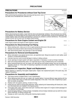 3
3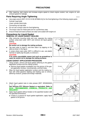 4
4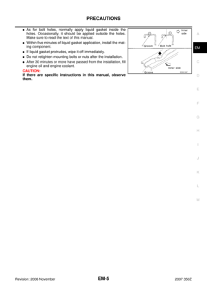 5
5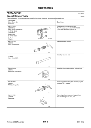 6
6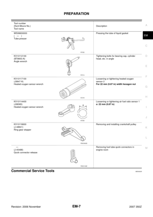 7
7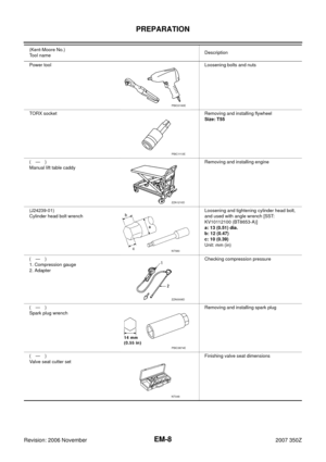 8
8 9
9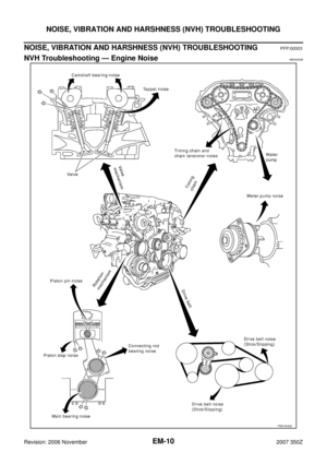 10
10 11
11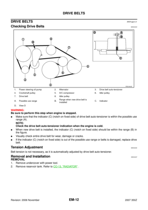 12
12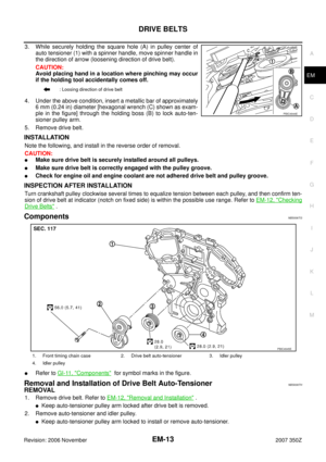 13
13 14
14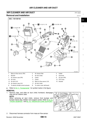 15
15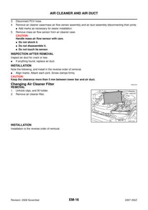 16
16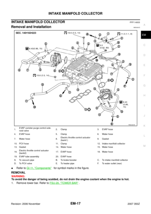 17
17 18
18 19
19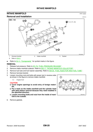 20
20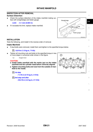 21
21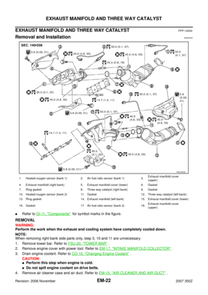 22
22 23
23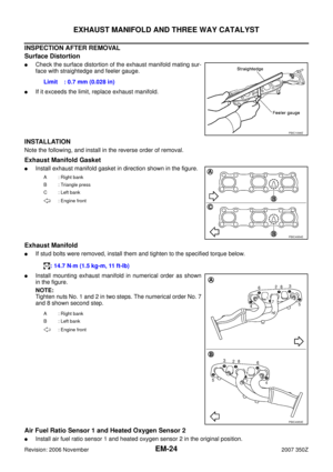 24
24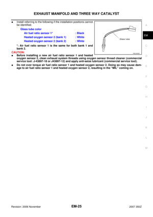 25
25 26
26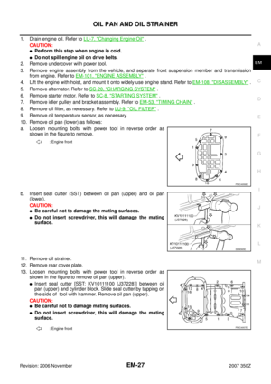 27
27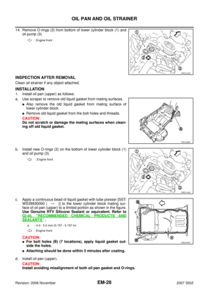 28
28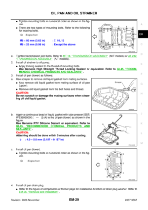 29
29 30
30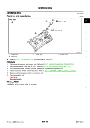 31
31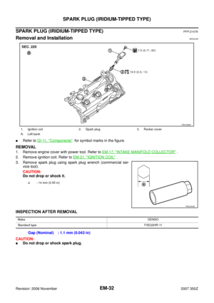 32
32 33
33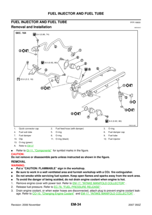 34
34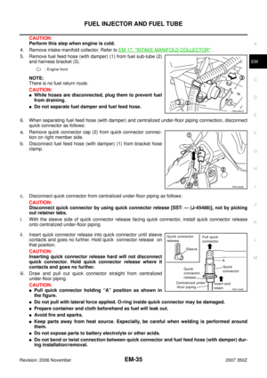 35
35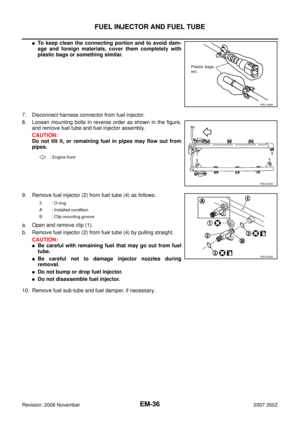 36
36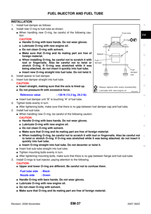 37
37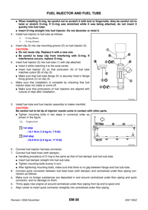 38
38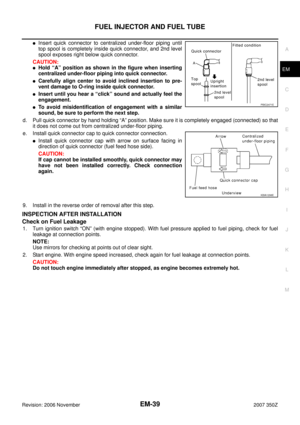 39
39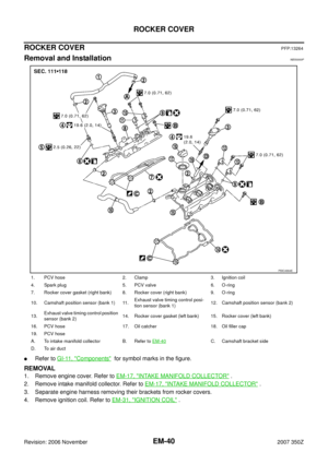 40
40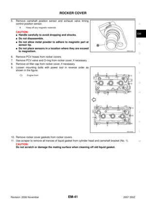 41
41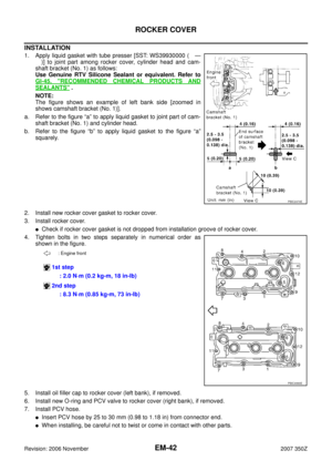 42
42 43
43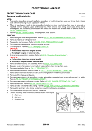 44
44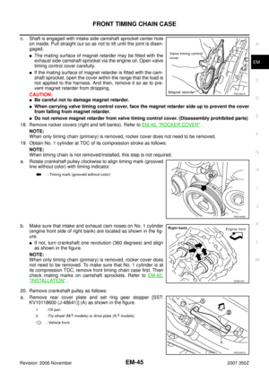 45
45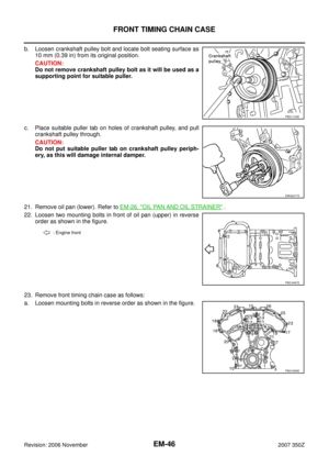 46
46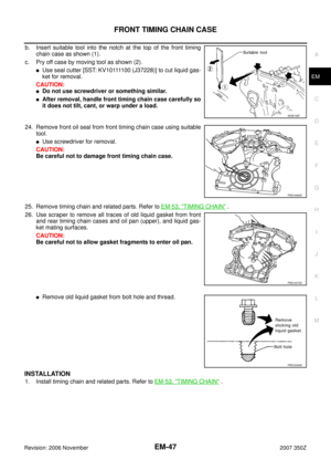 47
47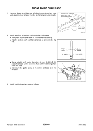 48
48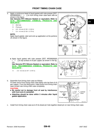 49
49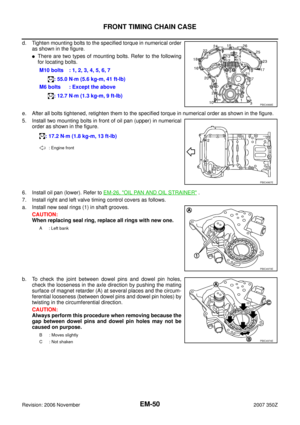 50
50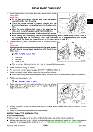 51
51 52
52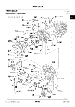 53
53 54
54 55
55 56
56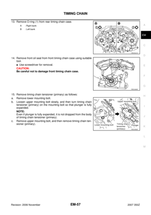 57
57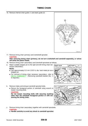 58
58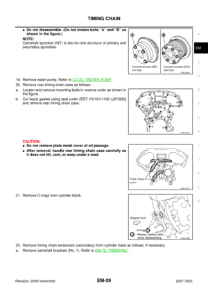 59
59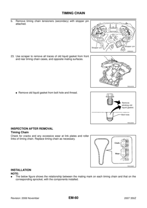 60
60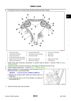 61
61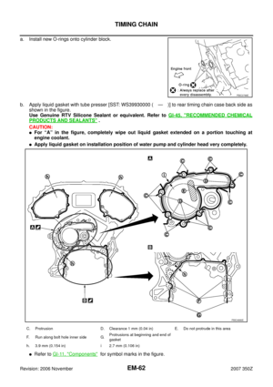 62
62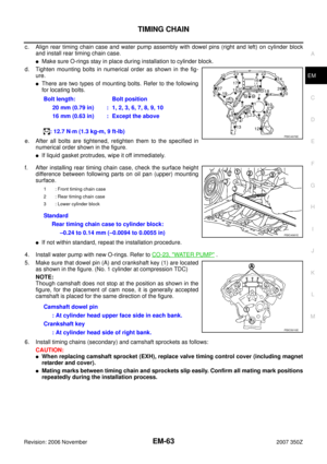 63
63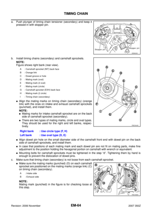 64
64 65
65 66
66 67
67 68
68 69
69 70
70 71
71 72
72 73
73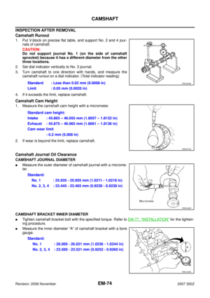 74
74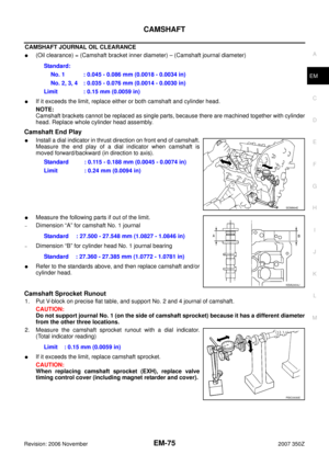 75
75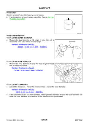 76
76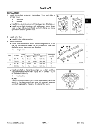 77
77 78
78 79
79 80
80 81
81 82
82 83
83 84
84 85
85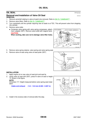 86
86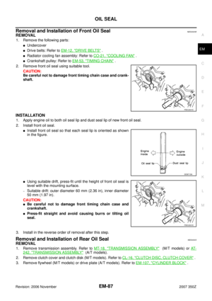 87
87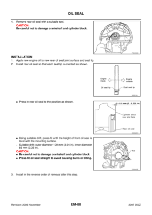 88
88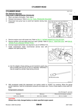 89
89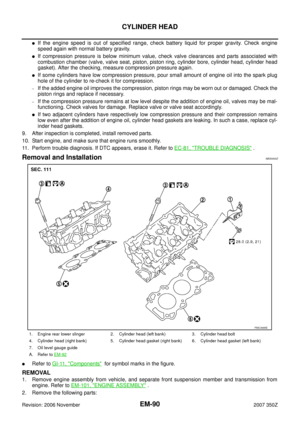 90
90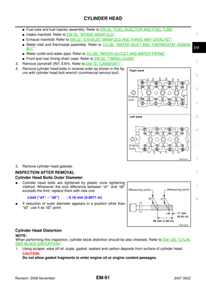 91
91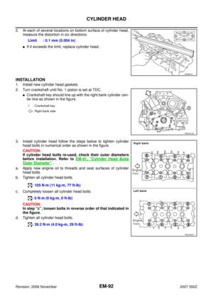 92
92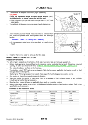 93
93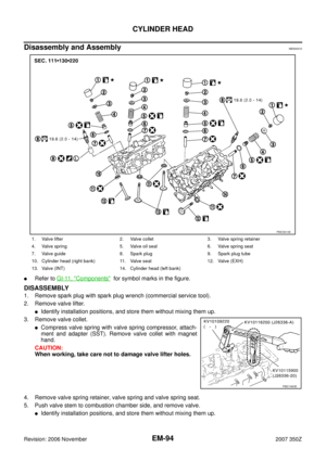 94
94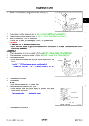 95
95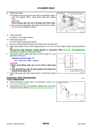 96
96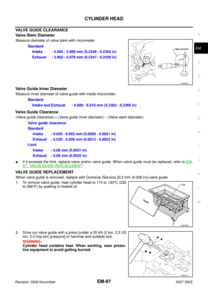 97
97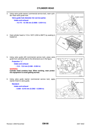 98
98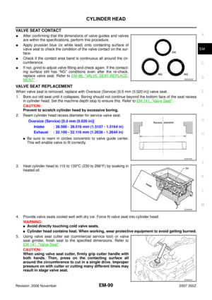 99
99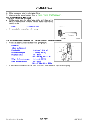 100
100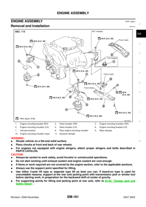 101
101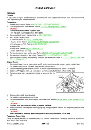 102
102 103
103 104
104 105
105 106
106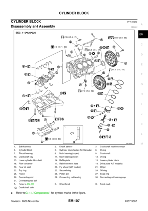 107
107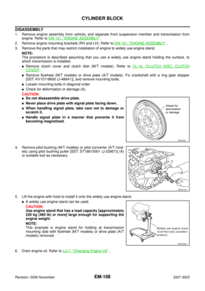 108
108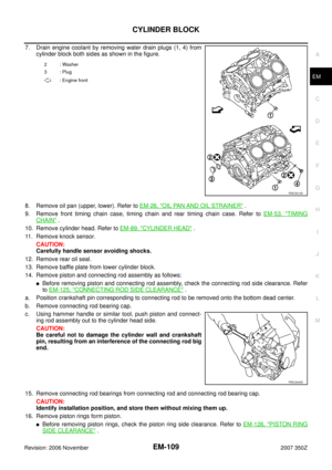 109
109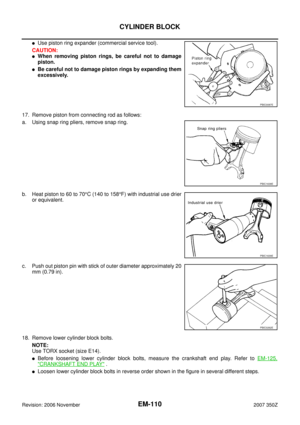 110
110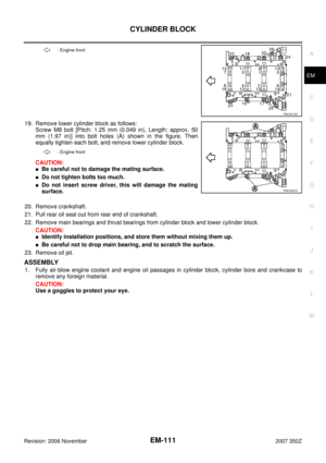 111
111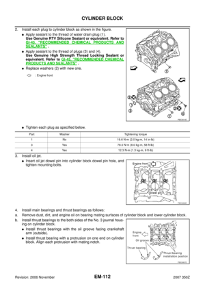 112
112 113
113 114
114 115
115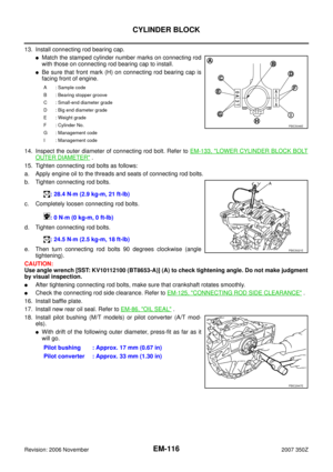 116
116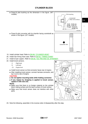 117
117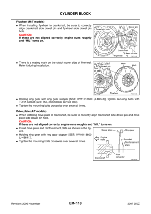 118
118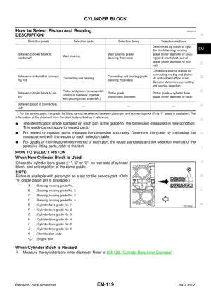 119
119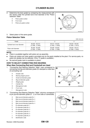 120
120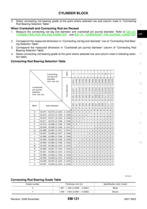 121
121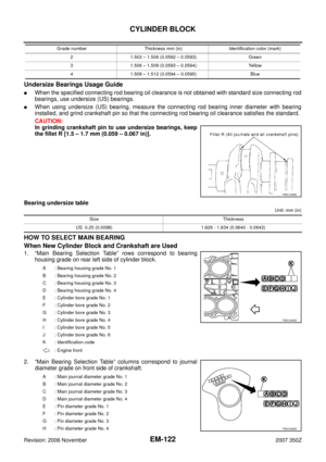 122
122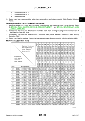 123
123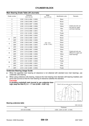 124
124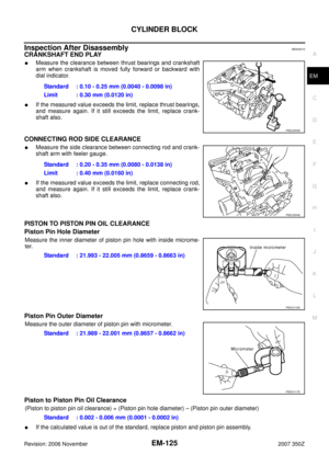 125
125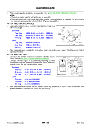 126
126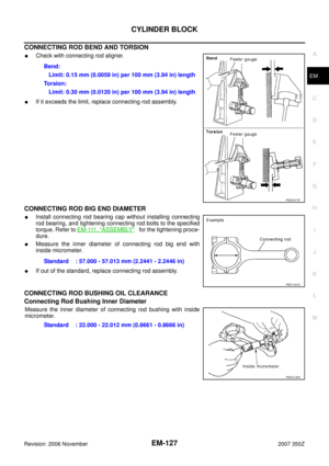 127
127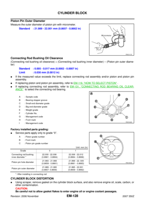 128
128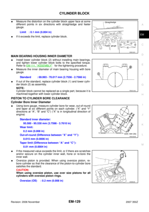 129
129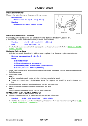 130
130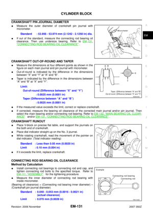 131
131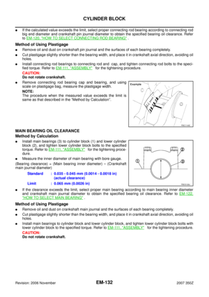 132
132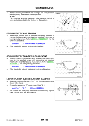 133
133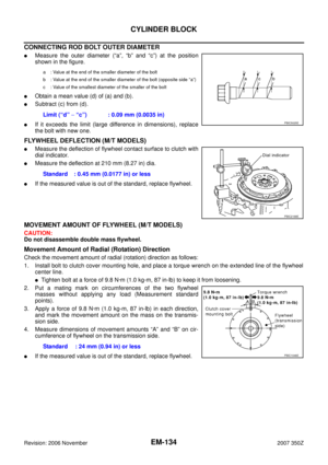 134
134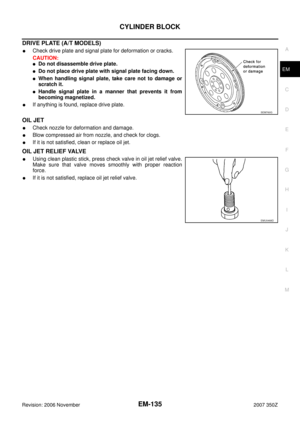 135
135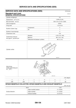 136
136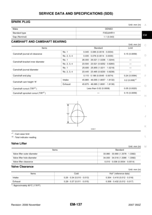 137
137 138
138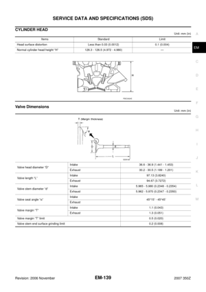 139
139 140
140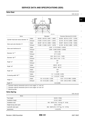 141
141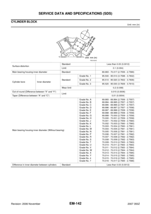 142
142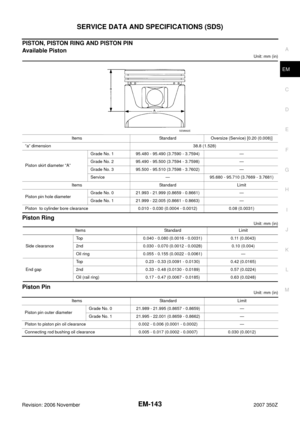 143
143 144
144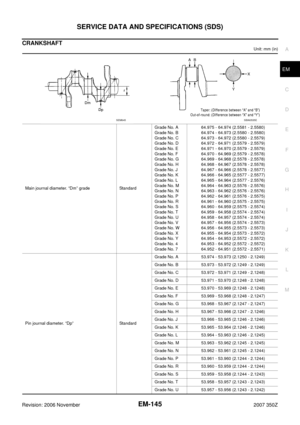 145
145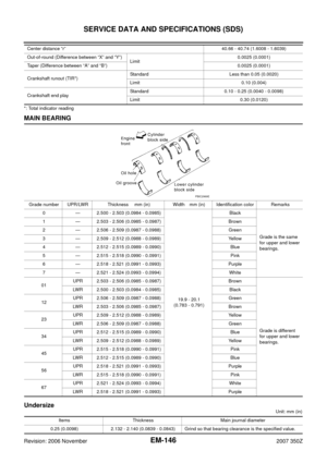 146
146 147
147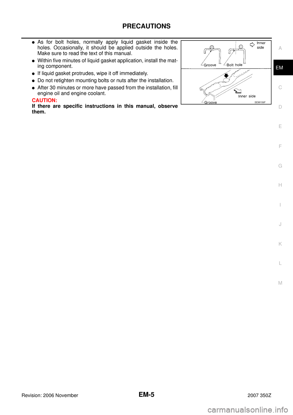


Tube presserPressing the tube of liquid gasket
KV10112100
(BT8653-A)
Angle")

Tool nameDescription
Power toolLoosening bolts and nuts
TORX socketRemoving and installing flywheel
Size: T55
(—)
Manual lift table")