INTAKE MANIFOLD COLLECTOR
EM-17
C
D
E
F
G
H
I
J
K
L
MA
EM
Revision: 2006 November2007 350Z
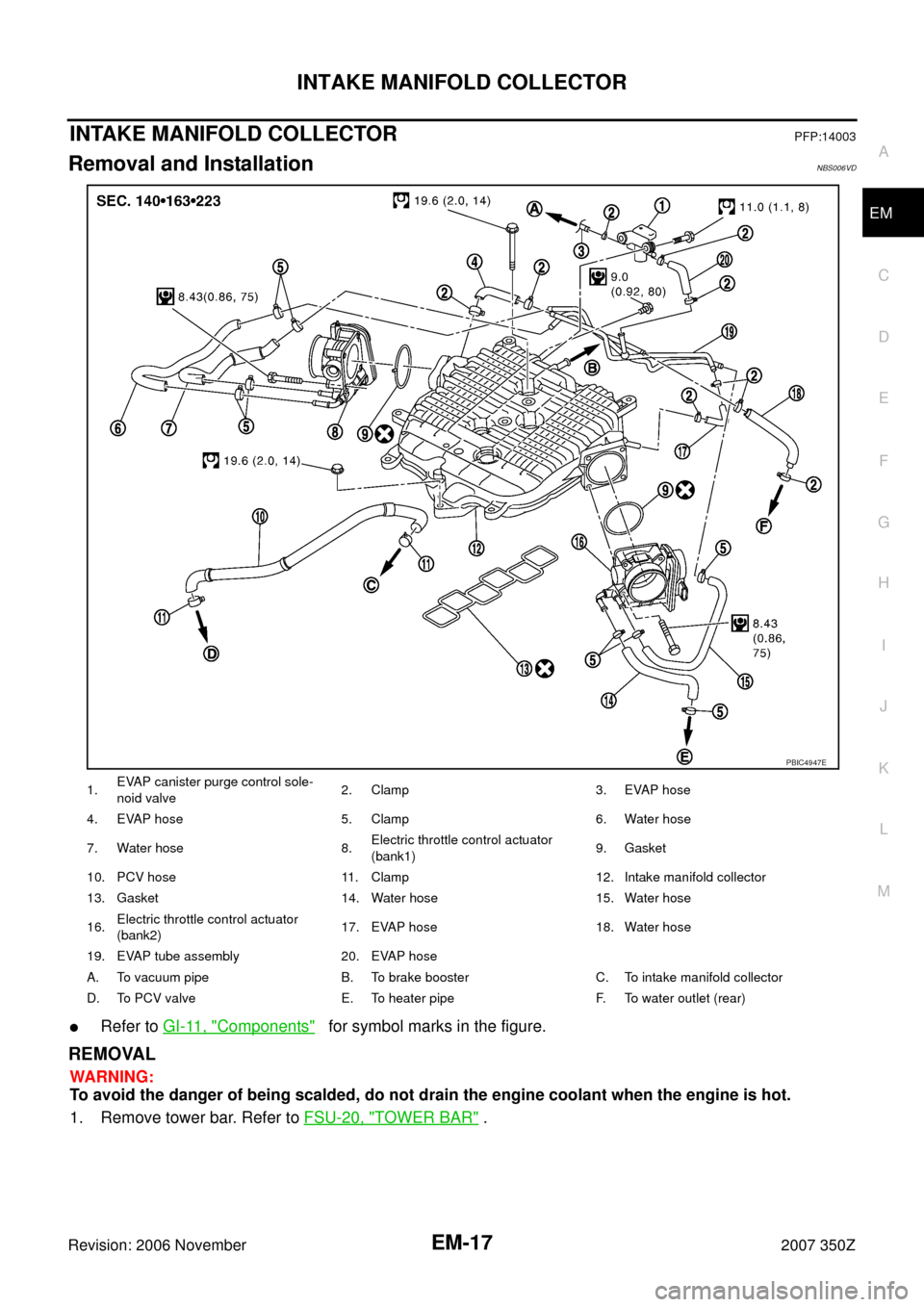
INTAKE MANIFOLD COLLECTORPFP:14003
Removal and InstallationNBS006VD
�Refer to GI-11, "Components" for symbol marks in the figure.
REMOVAL
WARNING:
To avoid the danger of being scalded, do not drain the engine coolant when the engine is hot.
1. Remove tower bar. Refer to FSU-20, "
TOWER BAR" .
1.EVAP canister purge control sole-
noid valve2. Clamp 3. EVAP hose
4. EVAP hose 5. Clamp 6. Water hose
7. Water hose 8.Electric throttle control actuator
(bank1)9. Gasket
10. PCV hose 11. Clamp 12. Intake manifold collector
13. Gasket 14. Water hose 15. Water hose
16.Electric throttle control actuator
(bank2)17. EVAP hose 18. Water hose
19. EVAP tube assembly 20. EVAP hose
A. To vacuum pipe B. To brake booster C. To intake manifold collector
D. To PCV valve E. To heater pipe F. To water outlet (rear)
PBIC4947E
EXHAUST MANIFOLD AND THREE WAY CATALYST
EM-23
C
D
E
F
G
H
I
J
K
L
MA
EM
Revision: 2006 November2007 350Z
5. Remove undercover with power tool.
6. Disconnect heated oxygen sensor harness connectors.
CAUTION:
�Be careful not to damage heated oxygen sensor 2.
�Discard any heated oxygen sensor 2 which has been dropped onto a hard surface such as a
concrete floor. Replace with a new sensor.
7. Remove exhaust mounting bracket between three way catalysts (right and left bank) and transmission.
Refer to EX-3, "
EXHAUST SYSTEM" .
8. Remove exhaust front tube and three way catalysts (right and left bank).
9. Disconnect harness connector and remove air fuel ratio sensor
1 on both banks using heated oxygen sensor wrench (SST).
�Put marks to identify installation positions of each air fuel ratio
sensor 1.
CAUTION:
�Be careful not to damage air fuel ratio sensor 1.
�Discard any air fuel ratio sensor 1 which has been
dropped onto a hard surface such as a concrete floor.
Replace with a new sensor.
10. Disconnect steering lower joint at power steering gear assembly side, and release steering lower shaft.
Refer to PS-17, "
POWER STEERING GEAR AND LINKAGE"
11. Remove water bypass pipe and heater pipe. Refer to CO-28, "WATER OUTLET AND WATER PIPING" .
12. Remove exhaust manifold cover.
13. Loosen mounting nuts in reverse order as shown in the figure to
remove exhaust manifold.
NOTE:
Disregard the numerical order No. 7 and 8 in removal.
14. Remove gaskets.
CAUTION:
Cover engine openings to avoid entry of foreign materials.
PBIC2299E
A : Right bank
B : Left bank
: Engine front
PBIC4953E
EM-102
ENGINE ASSEMBLY
Revision: 2006 November2007 350Z
REMOVAL
Outline
At first, remove engine and transmission assembly with front suspension member from vehicle downward.
Then separate engine from transmission.
Preparation
1. Release fuel pressure. Refer to EC-79, "FUEL PRESSURE RELEASE" .
2. Drain engine coolant from radiator. Refer to CO-10, "
Changing Engine Coolant" .
CAUTION:
�Perform this step when engine is cold.
�Do not spill engine coolant on drive belts.
3. Disconnect both battery cables. Refer to SC-4, "
BATTERY" .
4. Remove the following parts:
�Tower bar: Refer to FSU-20, "TOWER BAR" .
�Engine cover: Refer to EM-17, "INTAKE MANIFOLD COLLECTOR" .
�Cowl top cover (RH): Refer to EI-20, "COWL TOP" .
�Undercover
�Drive belts: Refer to EM-12, "DRIVE BELTS" .
�Front road wheels and tires
5. Remove air cleaner case and air duct. Refer to EM-15, "
AIR CLEANER AND AIR DUCT" .
6. Discharge refrigerant from A/C circuit. Refer to ATC-123, "
REFRIGERANT LINES" .
7. Remove radiator cooling fan assembly, reservoir tank and hoses. Refer to CO-21, "
COOLING FAN" and
CO-13, "
RADIATOR" .
Engine Room
1. Disconnect heater hose at engine-side, and fit a plug onto hose end to prevent engine coolant leak.
2. Disconnect ground cable (between vehicle to left cylinder head).
3. Disconnect battery positive cable harness at vehicle side and temporarily fasten it on engine.
4. Disconnect A/C piping from A/C compressor, and temporarily fasten it on vehicle with a rope.
5. Remove engine room harness connectors as shown in the fig-
ure.
6. Disconnect two body ground cables.
7. Disconnect brake booster vacuum hose.
8. Disconnect fuel feed hose (with damper) and EVAP hose. Refer to EM-34, "
FUEL INJECTOR AND FUEL
TUBE" .
CAUTION:
Fit plugs onto disconnected hoses to prevent fuel leak.
9. Remove reservoir tank of power steering oil pump, and piping from vehicle, and temporarily secure them
on engine.
CAUTION:
When temporarily securing, keep the reservoir tank upright to avoid a fluid leak.
Passenger Room Side
Follow procedure below to disconnect engine room harness connectors at passenger room side, and tempo-
rarily secure them on engine.
PBIC1105E
CYLINDER BLOCK
EM-107
C
D
E
F
G
H
I
J
K
L
MA
EM
Revision: 2006 November2007 350Z
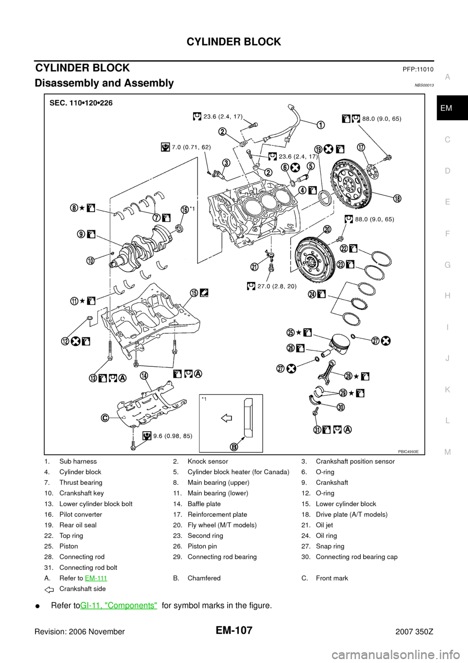
CYLINDER BLOCKPFP:11010
Disassembly and AssemblyNBS00013
�Refer toGI-11, "Components" for symbol marks in the figure.
1. Sub harness 2. Knock sensor 3. Crankshaft position sensor
4. Cylinder block 5. Cylinder block heater (for Canada) 6. O-ring
7. Thrust bearing 8. Main bearing (upper) 9. Crankshaft
10. Crankshaft key 11. Main bearing (lower) 12. O-ring
13. Lower cylinder block bolt 14. Baffle plate 15. Lower cylinder block
16. Pilot converter 17. Reinforcement plate 18. Drive plate (A/T models)
19. Rear oil seal 20. Fly wheel (M/T models) 21. Oil jet
22. Top ring 23. Second ring 24. Oil ring
25. Piston 26. Piston pin 27. Snap ring
28. Connecting rod 29. Connecting rod bearing 30. Connecting rod bearing cap
31. Connecting rod bolt
A. Refer to E M - 111
B. Chamfered C. Front mark
Crankshaft side
PBIC4993E