Page 3 of 148

PRECAUTIONS
EM-3
C
D
E
F
G
H
I
J
K
L
MA
EM
Revision: 2006 November2007 350Z
PRECAUTIONSPFP:00001
Precautions for Procedures without Cowl Top CoverNBS003FC
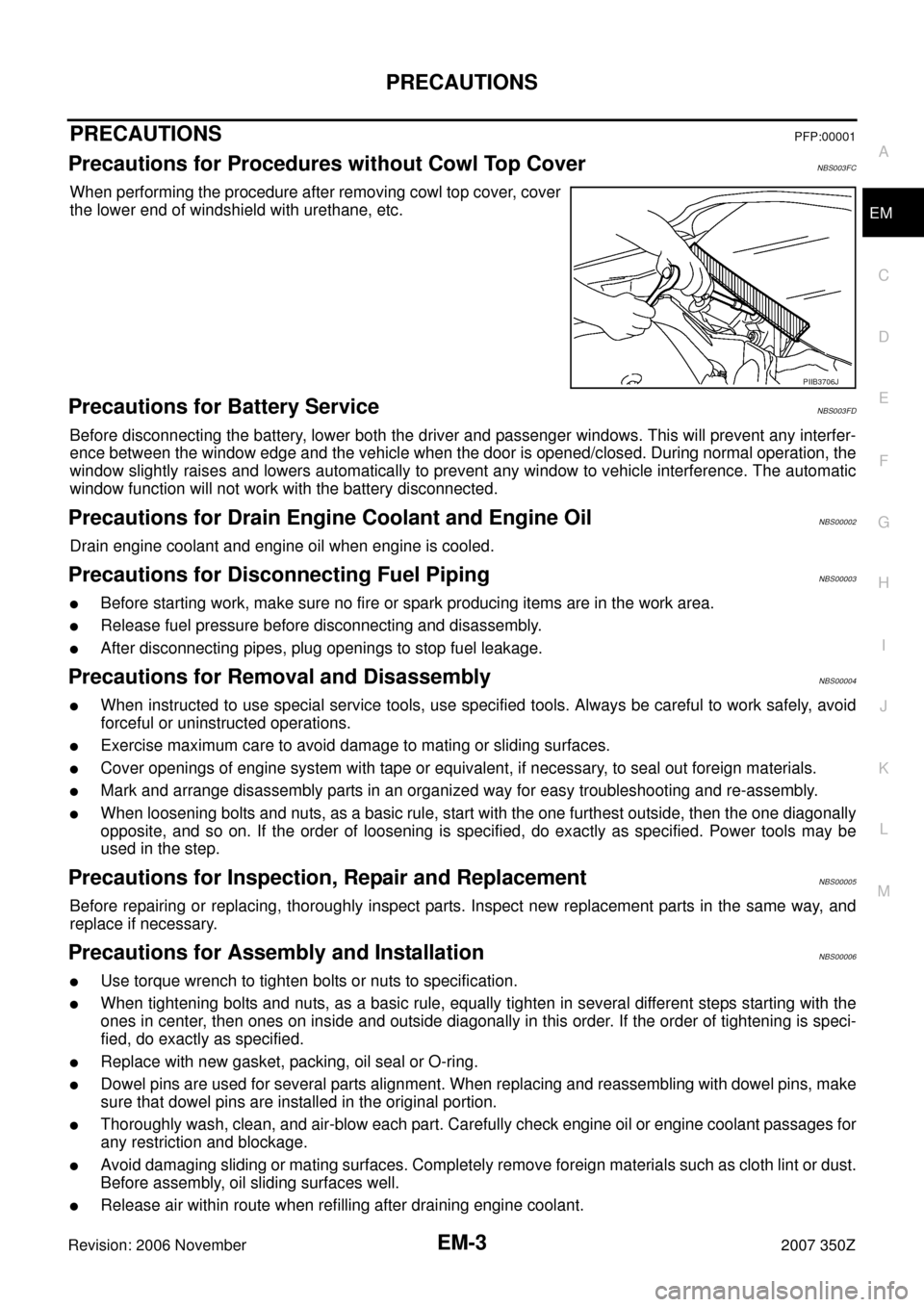
When performing the procedure after removing cowl top cover, cover
the lower end of windshield with urethane, etc.
Precautions for Battery ServiceNBS003FD
Before disconnecting the battery, lower both the driver and passenger windows. This will prevent any interfer-
ence between the window edge and the vehicle when the door is opened/closed. During normal operation, the
window slightly raises and lowers automatically to prevent any window to vehicle interference. The automatic
window function will not work with the battery disconnected.
Precautions for Drain Engine Coolant and Engine OilNBS00002
Drain engine coolant and engine oil when engine is cooled.
Precautions for Disconnecting Fuel PipingNBS00003
�Before starting work, make sure no fire or spark producing items are in the work area.
�Release fuel pressure before disconnecting and disassembly.
�After disconnecting pipes, plug openings to stop fuel leakage.
Precautions for Removal and DisassemblyNBS00004
�When instructed to use special service tools, use specified tools. Always be careful to work safely, avoid
forceful or uninstructed operations.
�Exercise maximum care to avoid damage to mating or sliding surfaces.
�Cover openings of engine system with tape or equivalent, if necessary, to seal out foreign materials.
�Mark and arrange disassembly parts in an organized way for easy troubleshooting and re-assembly.
�When loosening bolts and nuts, as a basic rule, start with the one furthest outside, then the one diagonally
opposite, and so on. If the order of loosening is specified, do exactly as specified. Power tools may be
used in the step.
Precautions for Inspection, Repair and ReplacementNBS00005
Before repairing or replacing, thoroughly inspect parts. Inspect new replacement parts in the same way, and
replace if necessary.
Precautions for Assembly and InstallationNBS00006
�Use torque wrench to tighten bolts or nuts to specification.
�When tightening bolts and nuts, as a basic rule, equally tighten in several different steps starting with the
ones in center, then ones on inside and outside diagonally in this order. If the order of tightening is speci-
fied, do exactly as specified.
�Replace with new gasket, packing, oil seal or O-ring.
�Dowel pins are used for several parts alignment. When replacing and reassembling with dowel pins, make
sure that dowel pins are installed in the original portion.
�Thoroughly wash, clean, and air-blow each part. Carefully check engine oil or engine coolant passages for
any restriction and blockage.
�Avoid damaging sliding or mating surfaces. Completely remove foreign materials such as cloth lint or dust.
Before assembly, oil sliding surfaces well.
�Release air within route when refilling after draining engine coolant.
PIIB3706J
Page 4 of 148

EM-4
PRECAUTIONS
Revision: 2006 November2007 350Z
�After repairing, start engine and increase engine speed to check engine coolant, fuel, engine oil, and
exhaust gases for leakage.
Parts Requiring Angle TighteningNBS00007
�Use angle wrench [SST: KV10112100 (BT8653-A)] for the final tightening of the following engine parts:
–Cylinder head bolts
–Lower cylinder block bolts
–Connecting rod cap bolts
�Do not use a torque value for final tightening.
�The torque value for these parts are for a preliminary step.
�Ensure thread and seat surfaces are clean and coated with engine oil.
Precautions for Liquid GasketNBS00008
REMOVAL OF LIQUID GASKET SEALING
�After removing mounting bolts and nuts, separate the mating
surface using seal cutter (SST) and remove old liquid gasket
sealing.
CAUTION:
Be careful not to damage the mating surfaces.
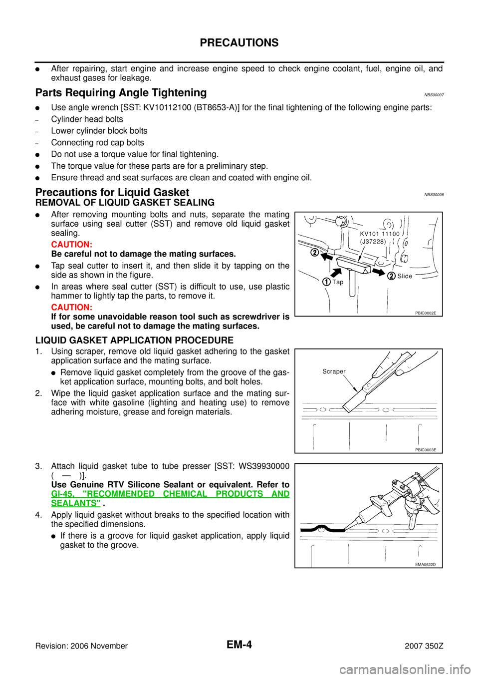
�Tap seal cutter to insert it, and then slide it by tapping on the
side as shown in the figure.
�In areas where seal cutter (SST) is difficult to use, use plastic
hammer to lightly tap the parts, to remove it.
CAUTION:
If for some unavoidable reason tool such as screwdriver is
used, be careful not to damage the mating surfaces.
LIQUID GASKET APPLICATION PROCEDURE
1. Using scraper, remove old liquid gasket adhering to the gasket
application surface and the mating surface.
�Remove liquid gasket completely from the groove of the gas-
ket application surface, mounting bolts, and bolt holes.
2. Wipe the liquid gasket application surface and the mating sur-
face with white gasoline (lighting and heating use) to remove
adhering moisture, grease and foreign materials.
3. Attach liquid gasket tube to tube presser [SST: WS39930000
(—)].
Use Genuine RTV Silicone Sealant or equivalent. Refer to
GI-45, "
RECOMMENDED CHEMICAL PRODUCTS AND
SEALANTS" .
4. Apply liquid gasket without breaks to the specified location with
the specified dimensions.
�If there is a groove for liquid gasket application, apply liquid
gasket to the groove.
PBIC0002E
PBIC0003E
EMA0622D
Page 50 of 148

EM-50
FRONT TIMING CHAIN CASE
Revision: 2006 November2007 350Z
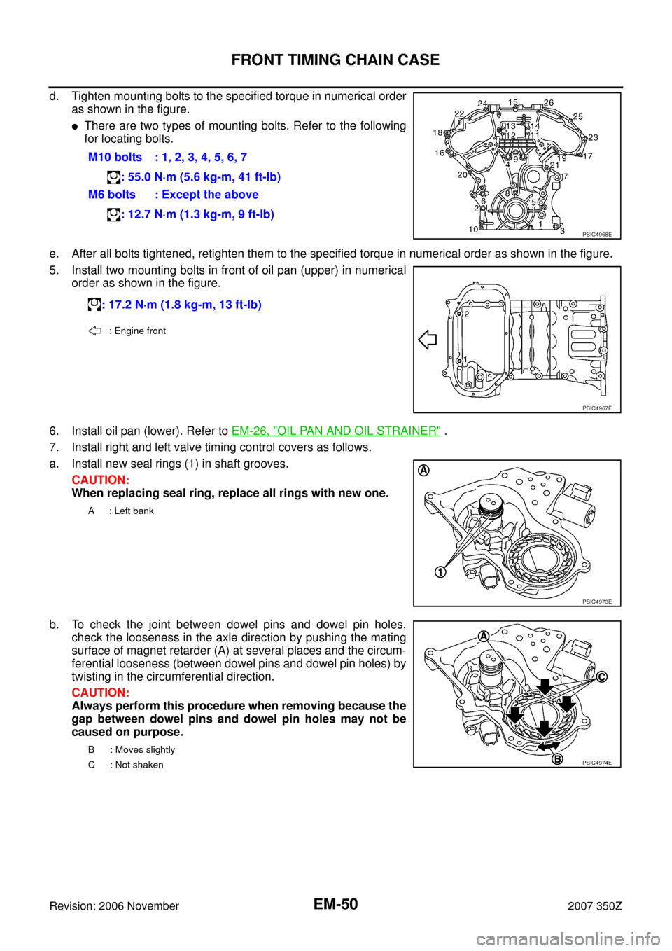
d. Tighten mounting bolts to the specified torque in numerical order
as shown in the figure.
�There are two types of mounting bolts. Refer to the following
for locating bolts.
e. After all bolts tightened, retighten them to the specified torque in numerical order as shown in the figure.
5. Install two mounting bolts in front of oil pan (upper) in numerical
order as shown in the figure.
6. Install oil pan (lower). Refer to EM-26, "
OIL PAN AND OIL STRAINER" .
7. Install right and left valve timing control covers as follows.
a. Install new seal rings (1) in shaft grooves.
CAUTION:
When replacing seal ring, replace all rings with new one.
b. To check the joint between dowel pins and dowel pin holes,
check the looseness in the axle direction by pushing the mating
surface of magnet retarder (A) at several places and the circum-
ferential looseness (between dowel pins and dowel pin holes) by
twisting in the circumferential direction.
CAUTION:
Always perform this procedure when removing because the
gap between dowel pins and dowel pin holes may not be
caused on purpose.M10 bolts : 1, 2, 3, 4, 5, 6, 7
: 55.0 N·m (5.6 kg-m, 41 ft-lb)
M6 bolts : Except the above
: 12.7 N·m (1.3 kg-m, 9 ft-lb)
PBIC4968E
: 17.2 N·m (1.8 kg-m, 13 ft-lb)
: Engine front
PBIC4967E
A : Left bank
PBIC4973E
B : Moves slightly
C : Not shaken
PBIC4974E