EM-8
PREPARATION
Revision: 2006 November2007 350Z
(Kent-Moore No.)
Tool nameDescription
Power toolLoosening bolts and nuts
TORX socketRemoving and installing flywheel
Size: T55
(—)
Manual lift table caddyRemoving and installing engine
(J24239-01)
Cylinder head bolt wrenchLoosening and tightening cylinder head bolt,
and used with angle wrench [SST:
KV10112100 (BT8653-A)]
a: 13 (0.51) dia.
b: 12 (0.47)
c: 10 (0.39)
Unit: mm (in)
(—)
1. Compression gauge
2. AdapterChecking compression pressure
(—)
Spark plug wrenchRemoving and installing spark plug
(—)
Valve seat cutter setFinishing valve seat dimensions
PBIC0190E
PBIC1113E
ZZA1210D
NT583
ZZA0008D
PBIC3874E
NT048
EM-118
CYLINDER BLOCK
Revision: 2006 November2007 350Z
Flywheel (M/T models)
�When installing flywheel to crankshaft, be sure to correctly
align crankshaft side dowel pin and flywheel side dowel pin
hole.
CAUTION:
If these are not aligned correctly, engine runs roughly
and “MIL” turns on.
�There is a mating mark on the clutch cover side of flywheel.
Refer it during installation.
�Holding ring gear with ring gear stopper [SST: KV11018600 (J-48641)], tighten securing bolts with
TORX socket (size: T55, commercial service tool).
�Tighten the mounting bolts crosswise over several times.
Drive plate (A/T models)
�When installing drive plate to crankshaft, be sure to correctly align crankshaft side dowel pin and drive
plate side dowel pin hole.
CAUTION:
If these are not aligned correctly, engine runs roughly and “MIL” turns on.
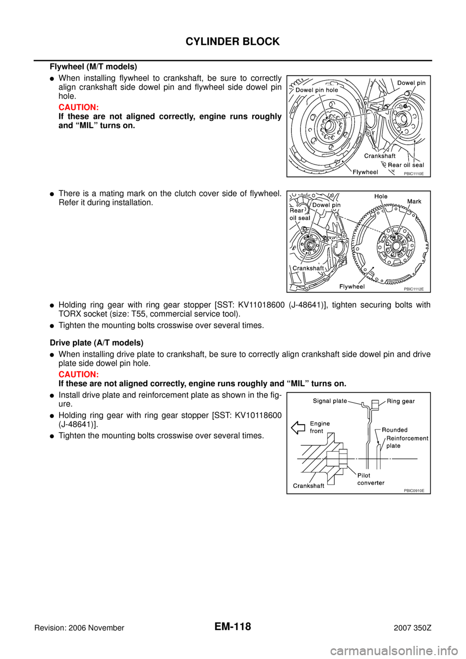
�Install drive plate and reinforcement plate as shown in the fig-
ure.
�Holding ring gear with ring gear stopper [SST: KV10118600
(J-48641)].
�Tighten the mounting bolts crosswise over several times.
PBIC1110E
PBIC1112E
PBIC0910E

Tool nameDescription
Power toolLoosening bolts and nuts
TORX socketRemoving and installing flywheel
Size: T55
(—)
Manual lift table")