Page 29 of 148

OIL PAN AND OIL STRAINER
EM-29
C
D
E
F
G
H
I
J
K
L
MA
EM
Revision: 2006 November2007 350Z
�Tighten mounting bolts in numerical order as shown in the fig-
ure.
�There are two types of mounting bolts. Refer to the following
for locating bolts.
e. Tighten transmission joint bolts. Refer to MT-18, "
TRANSMISSION ASSEMBLY" (M/T models) or AT- 2 4 2 ,
"TRANSMISSION ASSEMBLY" (A/T models).
2. Install oil strainer to oil pump.
�Apply locking sealant to the thread of mounting bolts.
Use Genuine High Strength Thread Locking Sealant or equivalent. Refer to GI-45, "
RECOM-
MENDED CHEMICAL PRODUCTS AND SEALANTS" .
3. Install oil pan (lower) as follows:
a. Use scraper to remove old liquid gasket from mating surfaces.
�Also remove old liquid gasket from mating surface of oil pan
(upper).
�Remove old liquid gasket from the bolt holes and thread.
CAUTION:
Do not scratch or damage the mating surfaces when clean-
ing off old liquid gasket.
b. Apply a continuous bead of liquid gasket with tube presser [SST:
WS39930000 ( — )] (A) to the oil pan (lower) as shown in the
figure.
Use Genuine RTV Silicone Sealant or equivalent. Refer to
GI-45, "
RECOMMENDED CHEMICAL PRODUCTS AND
SEALANTS" .
CAUTION:
Attaching should be done within 5 minutes after coating.
c. Install oil pan (lower).
�Tighten mounting bolts in numerical order as shown in the fig-
ure.
4. Install oil pan drain plug.
�Refer to the figure of components of former page for installation direction of drain plug washer. Refer to
EM-26, "
Removal and Installation" .
: Engine front
M8 × 92 mm (3.62 in) : 7, 10, 13
M8 × 25 mm (0.98 in) : Except the above
PBIC4957E
SEM958F
b : 4.0 – 5.0 mm (0.157 – 0.197 in)
PBIC4959E
: Engine front
PBIC4956E
Page 107 of 148
CYLINDER BLOCK
EM-107
C
D
E
F
G
H
I
J
K
L
MA
EM
Revision: 2006 November2007 350Z
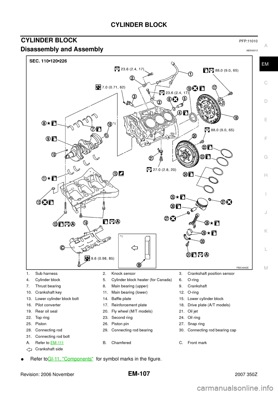
CYLINDER BLOCKPFP:11010
Disassembly and AssemblyNBS00013
�Refer toGI-11, "Components" for symbol marks in the figure.
1. Sub harness 2. Knock sensor 3. Crankshaft position sensor
4. Cylinder block 5. Cylinder block heater (for Canada) 6. O-ring
7. Thrust bearing 8. Main bearing (upper) 9. Crankshaft
10. Crankshaft key 11. Main bearing (lower) 12. O-ring
13. Lower cylinder block bolt 14. Baffle plate 15. Lower cylinder block
16. Pilot converter 17. Reinforcement plate 18. Drive plate (A/T models)
19. Rear oil seal 20. Fly wheel (M/T models) 21. Oil jet
22. Top ring 23. Second ring 24. Oil ring
25. Piston 26. Piston pin 27. Snap ring
28. Connecting rod 29. Connecting rod bearing 30. Connecting rod bearing cap
31. Connecting rod bolt
A. Refer to E M - 111
B. Chamfered C. Front mark
Crankshaft side
PBIC4993E
Page 108 of 148

EM-108
CYLINDER BLOCK
Revision: 2006 November2007 350Z
DISASSEMBLY
1. Remove engine assembly from vehicle, and separate front suspension member and transmission from
engine. Refer to EM-101, "
ENGINE ASSEMBLY" .
2. Remove engine mounting brackets (RH and LH). Refer to EM-101, "
ENGINE ASSEMBLY" .
3. Remove the parts that may restrict installation of engine to widely use engine stand.
NOTE:
The procedure is described assuming that you use a widely use engine stand holding the surface, to
which transmission is installed.
�Remove clutch cover and clutch disk (M/T models). Refer to CL-16, "CLUTCH DISC, CLUTCH
COVER" .
�Remove flywheel (M/T models) or drive plate (A/T models). Fix crankshaft with a ring gear stopper
[SST: KV10118600 (J-48641)], and remove mounting bolts.
�Loosen mounting bolts in diagonal order.
�Check for deformation or damage (A).
CAUTION:
�Do not disassemble drive plate.
�Never place drive plate with signal plate facing down.
�When handling signal plate, take care not to damage or
scratch it.
�Handle signal plate in a manner that prevents it from
becoming magnetized.
4. Remove pilot bushing (M/T models) or pilot converter (A/T mod-
els) using pilot bushing puller [SST: ST16610001 (J-23907)] (A)
or suitable tool as necessary.
5. Lift the engine with hoist to install it onto the widely use engine stand.
�A widely use engine stand can be used.
CAUTION:
Use engine stand that has a load capacity [approximately
220 kg (485 lb) or more] large enough for supporting the
engine weight.
NOTE:
This example is engine stand for holding at transmission
mounting side with flywheel (M/T models) or drive plate (A/T
models) removed.
6. Drain engine oil. Refer to LU-7, "
Changing Engine Oil" .
SEM760G
PBIC5015E
PBIC0085E
Page 135 of 148
CYLINDER BLOCK
EM-135
C
D
E
F
G
H
I
J
K
L
MA
EM
Revision: 2006 November2007 350Z
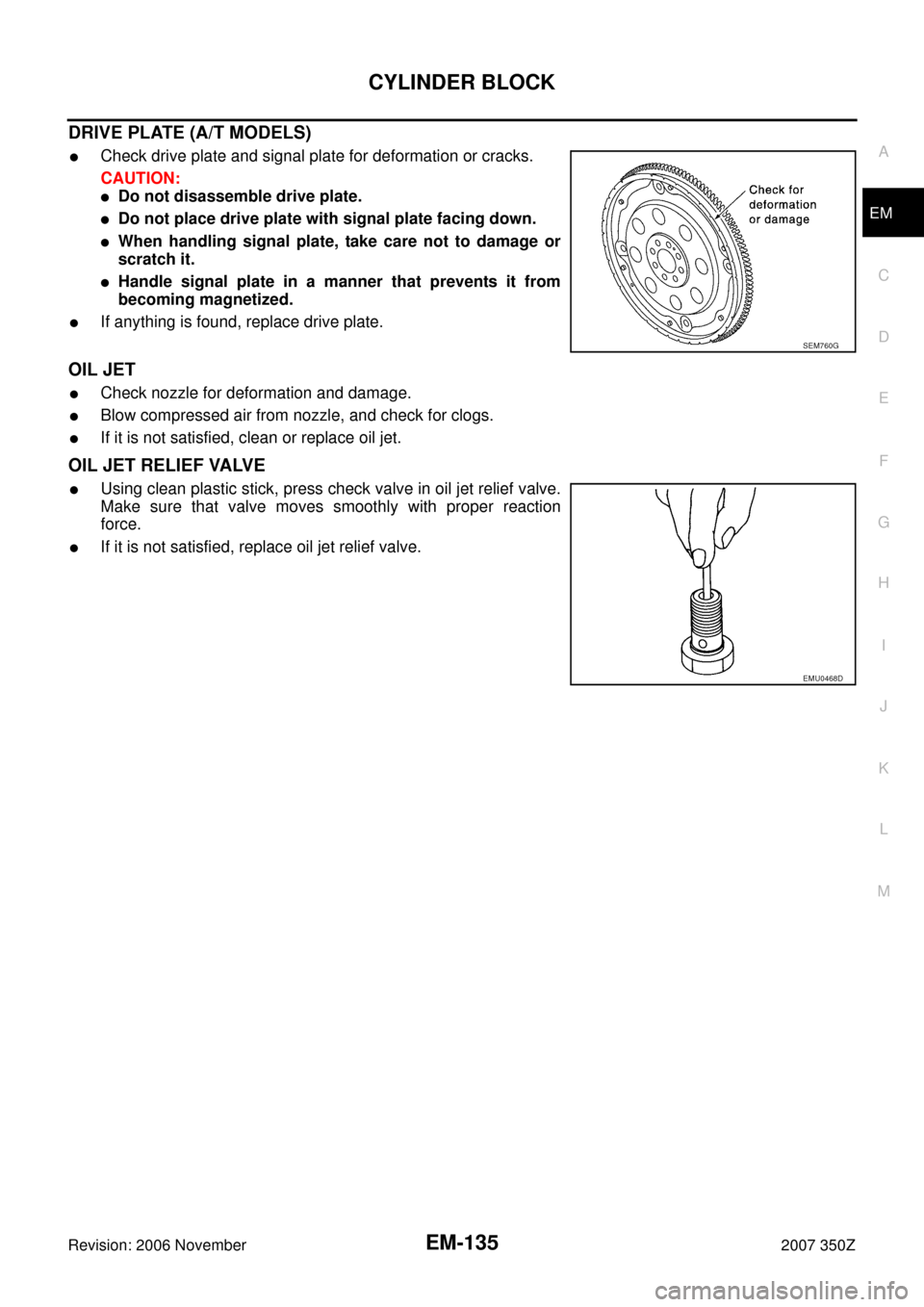
DRIVE PLATE (A/T MODELS)
�Check drive plate and signal plate for deformation or cracks.
CAUTION:
�Do not disassemble drive plate.
�Do not place drive plate with signal plate facing down.
�When handling signal plate, take care not to damage or
scratch it.
�Handle signal plate in a manner that prevents it from
becoming magnetized.
�If anything is found, replace drive plate.
OIL JET
�Check nozzle for deformation and damage.
�Blow compressed air from nozzle, and check for clogs.
�If it is not satisfied, clean or replace oil jet.
OIL JET RELIEF VALVE
�Using clean plastic stick, press check valve in oil jet relief valve.
Make sure that valve moves smoothly with proper reaction
force.
�If it is not satisfied, replace oil jet relief valve.
SEM760G
EMU0468D