ENGINE ASSEMBLY
EM-101
C
D
E
F
G
H
I
J
K
L
MA
EM
Revision: 2006 November2007 350Z
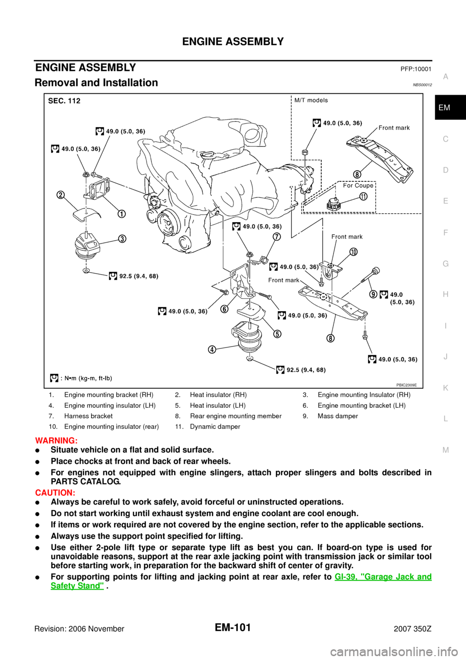
ENGINE ASSEMBLYPFP:10001
Removal and InstallationNBS00012
WARNING:
�Situate vehicle on a flat and solid surface.
�Place chocks at front and back of rear wheels.
�For engines not equipped with engine slingers, attach proper slingers and bolts described in
PARTS CATALOG.
CAUTION:
�Always be careful to work safely, avoid forceful or uninstructed operations.
�Do not start working until exhaust system and engine coolant are cool enough.
�If items or work required are not covered by the engine section, refer to the applicable sections.
�Always use the support point specified for lifting.
�Use either 2-pole lift type or separate type lift as best you can. If board-on type is used for
unavoidable reasons, support at the rear axle jacking point with transmission jack or similar tool
before starting work, in preparation for the backward shift of center of gravity.
�For supporting points for lifting and jacking point at rear axle, refer to GI-39, "Garage Jack and
Safety Stand" .
1. Engine mounting bracket (RH) 2. Heat insulator (RH) 3. Engine mounting Insulator (RH)
4. Engine mounting insulator (LH) 5. Heat insulator (LH) 6. Engine mounting bracket (LH)
7. Harness bracket 8. Rear engine mounting member 9. Mass damper
10. Engine mounting insulator (rear) 11. Dynamic damper
PBIC2309E
EM-104
ENGINE ASSEMBLY
Revision: 2006 November2007 350Z
3. Remove rear engine mounting member bolts.
4. Remove front suspension member mounting nuts. Refer to FSU-5, "
FRONT SUSPENSION ASSEMBLY" .
5. Carefully lower jack, or raise lift to remove the engine, transmission and front suspension member assem-
bly. When performing work, observe the following caution:
CAUTION:
�Confirm there is no interference with the vehicle.
�Make sure that all connection points have been disconnected.
�Keep in mind the center of the vehicle gravity changes. If necessary, use jack(s) to support the
vehicle at rear jacking point(s) to prevent it from falling it off the lift.
Separation Work
1. Install engine slingers into front of cylinder head (right bank) and
rear of cylinder head (left bank).
�To protect rocker cover against damage caused by tilting of
engine slinger, insert spacer between cylinder head and
engine rear lower slinger, in direction shown in the figure.
NOTE:
Spacer is a component part of engine rear upper slinger
assembly.
2. Remove power steering oil pump from engine side. Refer to PS-28, "
POWER STEERING OIL PUMP" .
3. Remove engine mounting insulators (RH and LH) under side nut.
4. Lift with hoist and separate engine and transmission assembly from front suspension member.
CAUTION:
�Before and during this lifting, always make sure that any harnesses are left connected.
�Avoid damage to and oil/grease smearing or spills onto engine mounting insulator.
5. Remove alternator. Refer to SC-20, "
CHARGING SYSTEM" .
6. Remove A/C compressor. Refer to ATC-125, "
Removal and Installation of Compressor" .
7. Remove starter motor. Refer to SC-8, "
STARTING SYSTEM" .
8. Separate engine from transmission. Refer to MT-18, "
TRANSMISSION ASSEMBLY" (M/T models) or AT-
242, "TRANSMISSION ASSEMBLY" (A/T models).
9. Remove engine mounting insulators (RH and LH) and brackets (RH and LH) from engine.
10. Remove rear engine mounting member and engine mounting insulator (rear) from transmission.
INSTALLATION
Note the following, and install in the reverse order of removal.
�Do not allow engine mounting insulator to be damage and careful no engine oil gets on it.
�For a location with a positioning pin, insert it securely into hole of mating part.
�For a part with a specified installation orientation, refer to component figure in EM-101, "Removal and
Installation" . Slinger bolts:
: 28.0 N·m (2.9 kg-m, 21 ft-lb)
PBIC2061E
KBIA1017E